|
5G DCI in Detail
DCI stands for Downlink Control Information. Simply put, it has several major functionalities as follows :
- Carrying the information to schedule (allocate physical resources) for Downlink Data (PDSCH)
- Carrying the information to schedule (allocate physical resources) for Uplink Data (PUSCH)
- Carrying the information to adjust Uplink Power (PUSCH, PUCCH power) for power control
The main purpose of DCI (Downlink Control Information) is the same as DCI in LTE(I strongly recommend you to read LTE DCI page first if you are not so familiar with what the DCI does). That is, it is a special set of information which schedules downlink data channel (e.g, PDSCH) or uplink data channel (e.g, PUSCH).
Followings are the list of DCI types and its contents defined in 38.212 - 7.3 Downlink control information.
< 38.212 - Table 7.3.1-1: DCI formats >
|
DCI Format |
Usage |
|
Scheduling of PUSCH in one cell |
|
|
Scheduling of PUSCH in one cell |
|
|
Scheduling of PDSCH in one cell DCI format 1_0 with CRC scrambled by C-RNTI DCI format 1_0 with CRC scrambled by C-RNTI for PDCCH Order DCI format 1_0 with CRC scrambled by RA-RNTI DCI format 1_0 with CRC scrambled by TC-RNTI |
|
|
Scheduling of PDSCH in one cell |
|
|
Notifying a group of UEs of the slot format |
|
|
Notifying a group of UEs of the PRB(s) and OFDM symbol(s) where UE may assume no transmission is intended for the UE |
|
|
Transmission of TPC commands for PUCCH and PUSCH |
|
|
Transmission of a group of TPC commands for SRS transmissions by one or more UEs |
|
|
Notifying the PRB(s) and OFDM symbol(s) where UE cancels the corresponding UL transmission from the UE |
|
|
Notifying the availability of soft resources |
|
|
Notifying the power saving information outside DRX Active Time for one or more UEs |
|
|
Format 3_0 |
Scheduling of NR sidelink in one cell |
|
Format 3_1 |
Scheduling of LTE sidelink in one cell |
NOTE : The contents of the table shown here is based on 38.212. This specification is very dry. As any other 3GPP spcecification, it just describes 'what should be done' and does not describe anything on the background story. To get any further technical background, you need to follow through a lot of TDocs. However, unless you are a firmware or DSP engineering implementing the physical channel, it will be very difficult to keep track of all the TDocs. One trick that I would recommend is to go through several latest TDocs not far away from TS (Technical Specification) because those TDocs usually have the summary of past stories and more detailed design concept. I put several TDocs under Reference section that might help you to get some background stories.
Once a DCI data is constructed, it goes to the channel coding process and transmitted over PDCCH. This process is described in followng page.
Format 0_0
This is used for the scheduling of PUSCH in one cell.
|
Field (Item) |
Bits |
Reference |
|
Identifier for DCI formats |
1 |
|
|
Frequency domain resource assignment |
4 |
Variable with UL BWP N_RB. Indicate PRB location within the BWP. The number of bits and the value is determined as described here. |
|
X |
Carries the row index of the items in pusch_allocationList in RRC |
|
|
Frequency Hopping Flag |
1 |
|
|
Modulation and coding scheme |
5 |
38.214 - 6.1.4 (See this table) |
|
New data indicator |
1 |
|
|
Redundancy version |
2 |
0,1,2,3 |
|
HARQ process number |
4 |
|
|
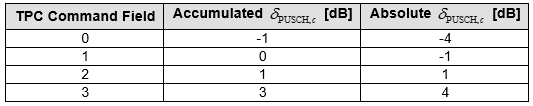
TPC command for scheduled PUSCH |
2 |
|
|
UL/SUL indicator |
0 or 1 |
0 bit : SUL not figured 1 bit : SUL configured |
Frequency domain resource assignment
The number of bits(bit length) for this field is determined by following formula
![]()
The meaning of ![]() varies depending on the search space where DCI_0_0 is transmitted.
varies depending on the search space where DCI_0_0 is transmitted.
- When stransmitted in common search space,
- When stransmitted in UE specific search space and meets following criteria
it indicates the size of the Initial Bandwidth Part
the total number of different DCI sizes monitored per slot <= 4
the total number of different DCI sizes with C-RNTI monitored per slot <= 3
it indicates the size of the Active Bandwidth Part
The value of this field is determined as follows.
 MSB bits are used to indicate the frequency offset
- = 1 if Frequency-hopping-offsets-set contains two offset values
- = 2 if Frequency-hopping-offsets-set contains four offset values
- Remaining Bits indicates PUSCH RIV
- the whole bits of this field indicates PUSCH RIV
Case 1 : PUSCH hopping = True and Resource allocation type 1
Case 2 : PUSCH hopping = False and Resource allocation type 1
< 38.214 v15.1 - Table 6.1.4.1-1: MCS index table for PUSCH with transform precoding and 64QAM >
|
MCS Index I_MCS |
Modulation Order Qm |
Target code Rate R x 1024 |
Spectral efficiency |
|
0 |
q |
240/ q |
0.2344 |
|
1 |
q |
314/ q |
0.3066 |
|
2 |
2 |
193 |
0.377 |
|
3 |
2 |
251 |
0.4902 |
|
4 |
2 |
308 |
0.6016 |
|
5 |
2 |
379 |
0.7402 |
|
6 |
2 |
449 |
0.877 |
|
7 |
2 |
526 |
1.0273 |
|
8 |
2 |
602 |
1.1758 |
|
9 |
2 |
679 |
1.3262 |
|
10 |
4 |
340 |
1.3281 |
|
11 |
4 |
378 |
1.4766 |
|
12 |
4 |
434 |
1.6953 |
|
13 |
4 |
490 |
1.9141 |
|
14 |
4 |
553 |
2.1602 |
|
15 |
4 |
616 |
2.4063 |
|
16 |
4 |
658 |
2.5703 |
|
17 |
6 |
466 |
2.7305 |
|
18 |
6 |
517 |
3.0293 |
|
19 |
6 |
567 |
3.3223 |
|
20 |
6 |
616 |
3.6094 |
|
21 |
6 |
666 |
3.9023 |
|
22 |
6 |
719 |
4.2129 |
|
23 |
6 |
772 |
4.5234 |
|
24 |
6 |
822 |
4.8164 |
|
25 |
6 |
873 |
5.1152 |
|
26 |
6 |
910 |
5.332 |
|
27 |
6 |
948 |
5.5547 |
|
28 |
1 |
reserved |
|
|
29 |
2 |
reserved |
|
|
30 |
4 |
reserved |
|
|
31 |
6 |
reserved |
|
Format 0_1
This is used for the scheduling of PUSCH in one cell.
< DCI format 0_1 with CRC scrambled by C-RNTI >
|
Field (Item) |
Bits |
Reference |
|
Identifier for DCI formats |
1 |
|
|
Carrier indicator |
0 or 3 |
|
|
UL/SUL Indicator |
0,1 |
0 - bit for UE not configured with SUL in the cell 1 - bit for UEs configured with SUL in the cell : according to Table 7.3.1.1.1-1 0 : non-spplementary Uplink 1 : spplementary Uplink |
|
Bandwidth part indicator |
0,1,2 |
Determined by BandwidthPart-Config in higher layer message and 38.212 - Table 7.3.1.1.2-1 |
|
Frequency domain resource assignment |
Variable |
|
|
4 |
Carries the row index of the items in pusch_allocationList in RRC Number of Bit Length is determined by log(I,2), where I is the number of elements in pusch_allocationList in RRC |
|
|
Frequency Hopping Flag |
0,1 |
|
|
Modulation and coding scheme |
5 |
38.214 - 6.1.4 (See this table) |
|
New data indicator |
1 |
|
|
Redundancy version |
2 |
0,1,2,3 |
|
HARQ process number |
4 |
|
|
1st Downlink assignment index |
1,2 |
|
|
2nd Downlink assignment index |
0,2 |
|
|
TPC command for scheduled PUSCH |
2 |
|
|
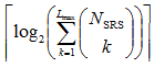
SRS resource indicator |
Variable |
|
|
Precoding information and number of layers (TPMI) |
0,2,3,4,5,6 |
Determined by ulTxConfig, Number of Antenna ports, PUSCH-tp, ULmaxRank |
|
Antenna ports |
2,3,4,5 |
Determined by PUSCH-tp, DL-DMRS-config-type, DL-DMRS-config-max-len, Rank |
|
SRS request |
2 |
|
|
CSI request |
0,1,2,3,4,5,6 |
Determined by ReportTriggerSize in RRC message. See Configure Aperiodic Trigger section for the details. |
|
CBG transmission information |
0,2,4,6,8 |
Determined by maxCodeBlockGroupPerTransportblock in RRC message |
|
PTRS - DMRS Association |
0,2 |
Determined by UL-PTRS-present, PUSCH-tp in RRC Message |
|
beta_offsetr Indicator |
0,2 |
0 - if uci-on-PUSCH.dynamic = Not Configured 2 - otherwise, see Table 7.3.1.1.2-27 |
|
DMRS Sequence Initialization |
0,1 |
0 - if PUSCH-tp=Disabled 1 - if PUSCH-tp=Enabled |
|
UL-SCH Indicator |
1 |
0 - UL-SCH shall not be transmitted on the PUSCH 1 - UL-SCH shall be transmitted on the PUSCH |
< DCI format 0_1 with CRC scrambled by CS-RNTI >
|
Field (Item) |
Bits |
Reference |
|
Identifier for DCI formats |
1 |
|
|
Carrier indicator |
0 or 3 |
|
|
DFI Flag |
0 or 1 |
1 bit when cg-RetransmissionTimer is configured
|
|
HARQ-ACK bitmap |
16 |
HARQ process indices are mapped in ascending order from MSB to LSB of the bitmap |
|
TPC command for scheduled PUSCH |
2 |
|
|
All the remaining bits |
|
set to 0 |
< 38.212 v17.3.0 - Table 7.3.1.1.1-1: UL/SUL indicator >
|
Value of UL/SUL indicator |
Uplink |
|
0 |
The non-supplementary uplink |
|
1 |
The supplementary uplink |
< 38.212 v15.3.0 - Table 7.3.1.1.2-1: Bandwidth part indicator >
|
Value of BWP indicator field |
Bandwidth part |
|
|
1 bit |
2 bits |
|
|
0 |
0 |
First bandwidth part configured by higher layers |
|
1 |
1 |
Second bandwidth part configured by higher layers |
|
|
10 |
Third bandwidth part configured by higher layers |
|
|
11 |
Fourth bandwidth part configured by higher layers |
< Frequency domain resource assignment >
The bit length of this field is determined as follows.
|
Resource Allocation Type |
Mumber of Bits |
|
|
|
|
|
|
|
Bit Length : MSB Indicates Resource Allocation Type 0 : Resource Allocation Type 0 1 : Resource Allocation Type 1 |
The value of this field is determined as follows :
- Resource Allocation Type 0 only : Bitmap determined as described here.
- Resource Allocation Type 1 only : Determined depending on PUSCH Hopping field as follows
- Case 1 : PUSCH hopping = True
- MSB bits are used to indicate the frequency offset
- = 1 if Frequency-hopping-offsets-set contains two offset values
- = 2 if Frequency-hopping-offsets-set contains four offset values
- Remaining Bits indicates PUSCH RIV
- Case 2 : PUSCH hopping = False
- the whole bits of this field indicates PUSCH RIV
< 38.214-v15.3.0 Table 6.1.2.2.1-1: Nominal RBG size P >
|
Carrier Bandwidth Part Size |
Configuration 1 |
Configuration 2 |
|
1-36 |
2 |
4 |
|
37-72 |
4 |
8 |
|
73-144 |
8 |
16 |
|
145-275 |
16 |
16 |
NOTE : Which RBG(Resource Block Group) size to be used is determined by PUSCH-Config.rbg-Size in RRC message from gNB
|
SRS-ResourceSet.usage |
Bit Length of SRS Resource Indicator |
|
|
CodeBook |
|
N_SRS is the number of configured SRS resources in the SRS resource set associated with "usage". |
|
NonCodeBook |
|
|
< 38.212-Table 7.3.1.1.2-24: SRS request >
|
Value of SRS request field |
Triggered aperiodic SRS resource set(s) |
|
00 |
No aperiodic SRS resource set triggered |
|
01 |
SRS resource set(s) configured with higher layer parameter aperiodicSRS-ResourceTrigger set to 1 |
|
10 |
SRS resource set(s) configured with higher layer parameter aperiodicSRS-ResourceTrigger set to 2 |
|
11 |
SRS resource set(s) configured with higher layer parameter aperiodicSRS-ResourceTrigger set to 3 |
< Precoding information and number of layers >
|
txConfig(UL) |
Antenna |
PUSCH-tp |
maxRank |
CodebookSubset |
Bit Length |
Table in 38.212 |
|
NonCodeBook |
|
|
|
|
0 |
|
|
CodeBook |
4 ports |
Disabled |
2 or 3 or 4 |
|
4 or 5 or 6 |
7.3.1.1.2-2 |
|
CodeBook |
4 ports |
Disabled |
|
|
2 or 4 or 5 |
7.3.1.1.2-3 |
|
Enabled |
1 |
|
||||
|
CodeBook |
2 ports |
|
2 |
|
3 or 4 |
7.3.1.1.2-4 |
|
CodeBook |
2 ports |
|
1 |
|
2 or 3 |
7.3.1.1.2-5 |
NOTE : PUSCH-tp indicates PUSCH Transform Precoding. Refer to Transform Precoding section in Waveform Page if you want to know what this is.
NOTE : txConfig, PUSCH-tp, maxRank, codebook Subset are specified by PUSCH-Config in RRC.
|
PUSCH-tp |
DMRS-config-type |
DMRS-config-max-len |
Rank |
Bit Lenth |
Table in 38.212 |
|
Enabled |
1 |
1 |
|
2 |
7.3.1.1.2-6 |
|
1 |
2 |
|
4 |
7.3.1.1.2-7 |
|
|
Disabled |
1 |
1 |
1 |
3 |
7.3.1.1.2-8 |
|
1 |
1 |
2 |
3 |
7.3.1.1.2-9 |
|
|
1 |
1 |
3 |
3 |
7.3.1.1.2-10 |
|
|
1 |
1 |
4 |
3 |
7.3.1.1.2-11 |
|
|
Disabled |
1 |
2 |
1 |
4 |
7.3.1.1.2-12 |
|
1 |
2 |
2 |
4 |
7.3.1.1.2-13 |
|
|
1 |
2 |
3 |
4 |
7.3.1.1.2-14 |
|
|
1 |
2 |
4 |
4 |
7.3.1.1.2-15 |
|
|
Disabled |
2 |
1 |
1 |
4 |
7.3.1.1.2-16 |
|
2 |
1 |
2 |
4 |
7.3.1.1.2-17 |
|
|
2 |
1 |
3 |
4 |
7.3.1.1.2-18 |
|
|
2 |
1 |
4 |
4 |
7.3.1.1.2-19 |
|
|
Disabled |
2 |
2 |
1 |
5 |
7.3.1.1.2-20 |
|
2 |
2 |
2 |
5 |
7.3.1.1.2-21 |
|
|
2 |
2 |
3 |
5 |
7.3.1.1.2-22 |
|
|
2 |
2 |
4 |
5 |
7.3.1.1.2-23 |
NOTE : PUSCH-tp indicates PUSCH Transform Precoding. Refer to Transform Precoding section in Waveform Page if you want to know what this is.
|
UL-PTRS-present |
PUSCH-tp |
UL PTRS port |
UL-PTRS-ports |
Bit Length |
Table in 38.212 |
|
OFF |
Disabled |
|
|
0 |
N/A |
|
ON |
Enabled |
|
|
0 |
N/A |
|
ON |
Disabled |
|
|
0 |
N/A |
|
Otherwise |
0 |
1 |
2 |
7.3.1.1.2-25 |
|
|
0 |
2 |
2 |
7.3.1.1.2-26 |
||
|
1 |
2 |
2 |
7.3.1.1.2-26 |
||
Format 1_0
This is used for the scheduling of PDSCH in one cell.
< DCI format 1_0 with CRC scrambled by C-RNTI >
|
Field (Item) |
Bits |
Reference |
|
Identifier for DCI formats |
1 |
Always set to 1, meaning this is for DL |
|
Frequency domain resource assignment |
Variable |
Variable with DL BWP N_RB |
|
4 |
Carries the row index of the items in pdsch_allocationList in RRC |
|
|
VRB-to-PRB mapping |
1 |
According to 38.212 Table 7.3.1.1.2-33 0 : Non-Interleaved 1 : Inverleaved |
|
Modulation and coding scheme |
5 |
|
|
New data indicator |
1 |
|
|
Redundancy version |
2 |
|
|
HARQ process number |
4 |
|
|
Downlink assignment index |
2 |
|
|
TPC command for scheduled PUCCH |
2 |
|
|
PUCCH resource indicator |
3 |
|
|
PDSCH-to-HARQ_feedback timing indicator |
3 |
maps to k1={1,2,3,4,5,6,7,8} - NOTE 2 |
NOTE 1 : The meaning of ![]() varies depending on the search space where DCI_1_0 is transmitted.
varies depending on the search space where DCI_1_0 is transmitted.
When stransmitted in common search space,
it indicates the size of the Initial Bandwidth Part
When stransmitted in UE specific search space and meets following criteria
the total number of different DCI sizes monitored per slot <= 4
the total number of different DCI sizes with C-RNTI monitored per slot <= 3
it indicates the size of the Active Bandwidth Part
NOTE 2 : In case of DCI 1_1, this field indicates the index value of dl-DataToUL-ACK, dl-DataToUL-ACK-r16 configured in RRC, but this field in DCI 1_0 refers to the index of pre-defined set {1,2,3,4,5,6,7,8}. This is based on following specification.
38.213-9.2.3
For DCI format 1_0, the PDSCH-to-HARQ_feedback timing indicator field values map to {1, 2, 3, 4, 5, 6, 7, 8}. For a DCI format, other than DCI format 1_0, scheduling a PDSCH reception or a SPS PDSCH release, the PDSCH-to HARQ_feedback timing indicator field values, if present, map to values for a set of number of slots provided by dl- DataToUL-ACK, dl-DataToUL-ACK-r16, or dl-DataToUL-ACKForDCIFormat1_2
< DCI format 1_0 with CRC scrambled by C-RNTI for PDCCH Order>
|
Field (Item) |
Bits |
Reference |
|
Identifier for DCI formats |
1 |
Always set to 1, meaning this is for DL |
|
Frequency domain resource assignment |
Variable |
All Ones |
|
Random Access Preamble index |
6 |
6 bits according to ra-PreambleIndex |
|
UL/SUL indicator |
1 |
NOTE 1 |
|
SS/PBCH index |
6 |
NOTE 2 |
|
PRACH Mask index |
4 |
NOTE 3 |
|
Reserved bits |
12 or 10 |
NOTE 4 |
NOTE 1 : If the value of the "Random Access Preamble index" is not all zeros and if the UE is configured with supplementaryUplink in ServingCellConfig in the cell, this field indicates which UL carrier in the cell to transmit the PRACH according to Table 7.3.1.1.1-1( 0 = Non Supplimentary Uplink, 1 = Supplementary Uplink); otherwise, this field is reserved
NOTE 2 : If the value of the "Random Access Preamble index" is not all zeros, this field indicates the SS/PBCH that shall be used to determine the RACH occasion for the PRACH transmission; otherwise, this field is reserved.
NOTE 3 : If the value of the "Random Access Preamble index" is not all zeros, this field indicates the RACH occasion associated with the SS/PBCH indicated by "SS/PBCH index" for the PRACH transmission, according to Clause 5.1.1 of 38.321; otherwise, this field is reserved
NOTE 4 : 12 bits for operation in a cell with shared spectrum channel access; otherwise 10 bits
< DCI format 1_0 with CRC scrambled by RA-RNTI >
: This is used to schedule RAR (Msg2) in RACH Procedure
|
Field (Item) |
Bits |
Reference |
|
Frequency domain resource assignment |
Variable |
Variable with DL BWP N_RB
|
|
Time domain resource assignment |
4 |
Carries the row index of the items in pdsch_allocationList in RRC |
|
VRB-to-PRB mapping |
1 |
According to 38.212 Table 7.3.1.1.2-33 0 : Non-Interleaved 1 : Inverleaved |
|
Modulation and coding scheme |
5 |
|
|
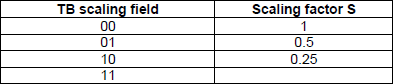
TB Scaling |
2 |
|
|
Reserved |
16 |
Reserved |
The meaning of ![]() varies depending on the search space where DCI_1_0 is transmitted.
varies depending on the search space where DCI_1_0 is transmitted.
When stransmitted in common search space in CORESET 0 ,
it indicates the size of the Initial Bandwidth Part
When stransmitted in UE specific search space and meets following criteria
the total number of different DCI sizes monitored per slot <= 4
the total number of different DCI sizes with C-RNTI monitored per slot <= 3
it indicates the size of the Active Bandwidth Part
TB Scaling is special parameters affecting the determination of Transport Block Size. This factor is multiplied to the result of the calculated Ninfo value.
< 38.214 - Table 5.1.3.2-2: Scaling factor of Ninfo for P-RNTI, RA-RNTI and MSGB-RNTI >
< DCI format 1_0 with CRC scrambled by TC-RNTI >
: This is used to schedule Contention Resolution (Msg4) in RACH Procedure
|
Field (Item) |
Bits |
Reference |
|
Identifier for DCI formats |
1 |
Always set to 1, meaning this is for DL |
|
Frequency domain resource assignment |
Variable |
Variable with DL BWP N_RB
|
|
Time domain resource assignment |
4 |
Carries the row index of the items in pdsch_allocationList in RRC |
|
VRB-to-PRB mapping |
1 |
According to 38.212 Table 7.3.1.1.2-33 0 : Non-Interleaved 1 : Inverleaved |
|
Modulation and coding scheme |
5 |
|
|
New data indicator |
1 |
|
|
Redundancy version |
2 |
|
|
HARQ process number |
4 |
|
|
Downlink assignment index |
2 |
Reserved |
|
TPC command for scheduled PUCCH |
2 |
|
|
PUCCH resource indicator |
3 |
|
|
PDSCH-to-HARQ_feedback timing indicator |
3 |
The meaning of ![]() varies depending on the search space where DCI_1_0 is transmitted.
varies depending on the search space where DCI_1_0 is transmitted.
When stransmitted in common search space in CORESET 0 ,
it indicates the size of the Initial Bandwidth Part
When stransmitted in UE specific search space and meets following criteria
the total number of different DCI sizes monitored per slot <= 4
the total number of different DCI sizes with C-RNTI monitored per slot <= 3
it indicates the size of the Active Bandwidth Part
< DCI format 1_0 with CRC scrambled by SI-RNTI >
: This is used to schedule SIB1 and other SIB messages
|
Field (Item) |
Bits |
Reference |
|
Frequency domain resource assignment |
Variable |
Variable with DL BWP N_RB
|
|
Time domain resource assignment |
4 |
Carries the row index of the items.
|
|
VRB-to-PRB mapping |
1 |
According to 38.212 Table 7.3.1.1.2-33 0 : Non-Interleaved 1 : Inverleaved |
|
Modulation and coding scheme |
5 |
|
|
Redundancy Version |
2 |
|
|
System Information Indicator |
1 |
0 : SIB 1 1 : SI messages |
|
Reserved |
15 |
Reserved |
[NOTE 1] SIB1 DCI refer to SI-RNTI / Type0Common in 38.214 - Table 5.1.2.1.1-1. As you see in the table, different TimeDomainResourceAllocation table is used depending on SSB/CORESET Multiplexing Pattern as summarized in the following table.
|
SSB/CORESET Multiplexing Pattern |
TimeDomainAllocation To Apply |
3GPP Table |
|
1 |
Default A for Normal CP |
|
|
2 |
Default B |
|
|
3 |
Defualt C |
< DCI format 1_0 with CRC scrambled by P-RNTI>
: This is used to schedule Paging messages
|
Field (Item) |
Bits |
Reference |
|
Short Message Indicator |
2 |
Refer to 38.212 - Table 7.3.1.2.1-1 |
|
Short Messages |
8 |
This field is set as reserved when 'Short Message Indicator' field is 01. Refer to 38.331 - Table 6.5-1 |
|
Frequency domain resource assignment |
Variable |
Variable with DL BWP N_RB
|
|
Time domain resource assignment |
4 |
Carries the row index of the items in pdsch_allocationList in RRC |
|
VRB-to-PRB mapping |
1 |
According to 38.212 Table 7.3.1.1.2-33 0 : Non-Interleaved 1 : Inverleaved |
|
Modulation and coding scheme |
5 |
|
|
TB Scaling |
2 |
|
|
Reserved |
6 |
Reserved |
< 38.212 - Table 7.3.1.2.1-1: Short Message indicator >
|
Bit Field |
Short Message Indicator |
|
00 |
Reserved |
|
01 |
Only scheduling information for Paging is present in the DCI |
|
10 |
Only short message is present in the DCI |
|
11 |
Both scheduling information for Paging and short message are present in the DCI |
< 38.331 - Table 6.5-1: Short messages >
|
Bit |
Short Message Indicator |
|
1 |
systemInfoModification If set to 1: indication of a BCCH modification other than SIB6, SIB7 and SIB8. |
|
2 |
etwsAndCmasIndication If set to 1: indication of an ETWS primary notification and/or an ETWS secondary notification and/or a CMAS notification |
|
3-[8] |
Not used in this release of the specification, and shall be ignored by UE if received. |
Format 1_1
This is used for the scheduling of PDSCH in one cell.
|
Field (Item) |
Bits |
Reference |
|
Carrier indicator |
0,3 |
|
|
Identifier for DCI formats |
1 |
Always set to 1, indicating a DL DCI format |
|
Bandwidth part indicator |
0,1,2 |
|
|
Frequency domain resource assignment |
Variable |
Variable with Resource Allocation Type |
|
4 |
Carries the row index of the items in pdsch_allocationList in RRC |
|
|
VRB-to-PRB mapping |
0,1 |
0 bit if only resource allocation type 0 is configured or if interleaved VRB-to-PRB mapping is not configured by high layers; 1 bit according to Table 7.3.1.1.2-33 otherwise, only applicable to resource allocation type 1 |
|
PRB bundling size indicator |
0,1 |
0 bit if the higher layer parameter prb-BundlingType is not configured or is set to 'static' 1 bit if the higher layer parameter prb-BundlingType is set to 'dynamic' |
|
Rate matching indicator |
0,1,2 |
Bit size is determined by higher layer parameters rateMatchPatternGroup1 and rateMatchPatternGroup2. |
|
ZP CSI-RS Trigger |
0,1,2 |
|
|
Modulation and coding scheme [TB1] |
5 |
|
|
New data indicator [TB1] |
1 |
|
|
Redundancy version [TB1] |
2 |
|
|
Modulation and coding scheme [TB2] |
5 |
|
|
New data indicator [TB2] |
1 |
|
|
Redundancy version [TB2] |
2 |
|
|
HARQ process number |
4 |
|
|
Downlink assignment index |
0,2,4 |
4 bits if more than one serving cell are configured in the DL and the higher layer parameter pdsch-HARQACK-Codebook=dynamic, where the 2 MSB bits are the counter DAI and the 2 LSB bits are the total DAI; 2 bits if only one serving cell is configured in the DL and the higher layer parameter pdsch-HARQ-ACKCodebook= dynamic, where the 2 bits are the counter DAI; 0 bits otherwise. |
|
TPC command for scheduled PUCCH |
2 |
|
|
PUCCH resource indicator |
3 |
|
|
PDSCH-to-HARQ_feedback timing indicator |
0,1,2,3 |
Number of bit is determined by log2(I). 'I' is the number of elements in the IE PUCCH-Config.dl-DataToUL-ACK |
|
4,5,6 |
Determined by dmrs Configuration Type and max Length See this summary table |
|
|
Transmission configuration indication |
0,3 |
0 bit if higher layer parameter tci-PresentInDCI is not enabled; 3 bits otherwise (See QCL page) |
|
SRS request |
2 |
|
|
CBG transmission information(CBGTI) |
0,2,4,6,8 |
|
|
CBG flushing out information(CBGFI) |
0,1 |
|
|
DMRS sequence initialization |
1 |
|
< Antenna port(s) and number of layers >
|
dmrs-Type |
maxLength |
Bit Field Length |
Table in 38.212 |
|
1 |
1 |
4 |
|
|
1 |
2 |
5 |
|
|
2 |
1 |
5 |
|
|
2 |
1 |
6 |
Format 2_0
This is used for notifying following information to UE. This DCI is scrambled by SFI_RNTI
- Slot format
- COT(Channel Occupancy Time) duration
- Available RB set
- Search space set group switching
If the higher layer parameter slotFormatCombToAddModList is configured
|
Field (Item) |
Bits |
Reference |
|
Identifier for DCI formats |
1 |
|
|
Slot format indicator |
Variable |
Bit size is determined by RRC message here |
Slot format indicator : a Bit string indicating Slot format indicator 1, Slot format indicator 2, , Slot format indicator N
If the higher layer parameter availableRB-SetsToAddModList is configured
|
Field (Item) |
Bits |
Reference |
|
Identifier for DCI formats |
1 |
|
|
Available RB set Indicator |
Variable |
Bit size is determined by RRC message here |
Available RB set Indicator : a Bit string indicating Available RB set Indicator 1, Available RB set Indicator 2, , Available RB set Indicator N
If the higher layer parameter co-DurationsPerCellToAddModList is configured
|
Field (Item) |
Bits |
Reference |
|
Identifier for DCI formats |
1 |
|
|
COT duration indicator |
Variable |
Bit size is determined by RRC message here |
COT duration indicator : a Bit string indicating COT duration indicator 1, COT duration indicator 2, , COT duration indicator N
If the higher layer parameter switchTriggerToAddModList is configured
|
Field (Item) |
Bits |
Reference |
|
Identifier for DCI formats |
1 |
|
|
Search space set group switching flag |
Variable |
Bit size is determined by RRC message here |
Search space set group switching flag : a Bit string indicating Search space set group switching flag1, Search space set group switching flag 2, , Search space set group switching flag N. (Details are in 38.213 - 11.1.1)
NOTE : Not every UE would support this DCI. That is, supporting DCI 2_0 decoding depends on UE capability. UE Capability Information related to DCI 2_0 decoding are listed below.
Phy-ParametersXDD-Diff ::= SEQUENCE {
dynamicSFI ENUMERATED {supported} OPTIONAL,
...
}
Phy-ParametersFRX-Diff ::= SEQUENCE {
dynamicSFI ENUMERATED {supported} OPTIONAL,
...
}
SharedSpectrumChAccessParamsPerBand-r16 ::= SEQUENCE {
...
dci-AvailableRB-Set-r16 ENUMERATED {supported} OPTIONAL,
dci-ChOccupancyDuration-r16 ENUMERATED {supported} OPTIONAL,
...
]
Format 2_1
This is used for notifying the PRB(s) and OFDM symbol(s) where UE may assume no transmission is intended for the UE. This DCI is scrambled by INT-RNTI.
|
Field (Item) |
Bits |
Reference |
|
Identifier for DCI formats |
1 |
|
|
Pre-emption indication |
Variable |
The size of DCI format 2_1 is configurable by higher layers up to 126 bits and each Pre-emtion indication is 14 bits(Details are in 38.213 - 11.2)
Format 2_2
This is used for the transmission of TPC commands for PUCCH, PUSCH. This DCI is scrambled by scrambled by TPC-PUSCH-RNTI or TPC-PUCCH-RNTI.
|
Field (Item) |
Bits |
Reference |
|
Identifier for DCI formats |
1 |
|
|
block number 1, block number 2,, block number N |
Variable |
Following fields are defined for each block
|
Field (Item) |
Bits |
Reference |
|
Closed loop indicator |
0,1 |
|
|
TPC Command |
2 bite |
Format 2_3
This is used for the transmission of a group of TPC commands for SRS transmissions by one or more UEs. Along with a TPC command, a SRS request may also be transmitted.
|
Field (Item) |
Bits |
Reference |
|
Identifier for DCI formats |
1 |
|
|
block number 1, block number 2,, block number B |
Variable |
Following fields are defined for each block
If the UE is configured with higher layer parameter srs-TPC-PDCCH-Group = typeA for an UL without PUCCH and
PUSCH or an UL on which the SRS power control is not tied with PUSCH power control
|
Field (Item) |
Bits |
Reference |
|
SRS Request |
0,2 |
|
|
TPC command number 1, TPC command number 2, ..., TPC command number N |
variable |
|
If the UE is configured with higher layer parameter srs-TPC-PDCCH-Group = typeB for an UL without PUCCH and
PUSCH or an UL on which the SRS power control is not tied with PUSCH power control
|
Field (Item) |
Bits |
Reference |
|
SRS Request |
0,2 |
|
|
TPC command number |
2 |
|
Format 2_4
This DCI is used for notifying the PRB(s) and OFDM symbol(s) where UE cancels the corresponding UL transmission from the UE (Details are in 38.213-11.2A). This is scrambled by ci-RNTI.
Format 2_5
This DCI is used for notifying the availability of soft resources (Details in 38.473-9.3.1). This is scrambled by AI-RNTI.
Format 2_6
This DCI is used for notifying the power saving information outside DRX Active Time for one or more UEs. This is scrambled by PS-RNTI
Structure of DCI format 2_6 is as follows :
block number 1, block number 2,, block number N
Structure of each block is as follows :
|
Field (Item) |
Bits |
Reference |
|
Wake-up indication |
1 |
|
|
SCell dormancy indication |
0,1,2,3,4,5 |
|
Reference
[1] 3GPP TS 38.212 NR;Multiplexing and channel coding
[2] 3GPP TSG RAN WG1 Meeting #92 : R1-1802117 : Discussion on DCI contents
[3] 3GPP TSG-RAN WG1 #92 : R1-1802905 : Remaining issues of the DCI contents and formats
[4] 3GPP TSG RAN WG1 Meeting #92 : R1-1801976 : DCI Contents and Formats
[5] 3GPP TSG RAN WG1 Meeting #92 : R1-1802097 : Remaining issues on MIMO related DCI design
[6] 3GPP TSG RAN WG1 Meeting #92 : R1-1802482 : DCI contents and formats
[7] 3GPP TSG RAN WG1 Meeting #92 : R1-1802597 : Remaining issues in DCI contents and formats
[8] 3GPP TSG RAN WG1 Meeting #92 : R1-1802209 : Remaining issues on DCI contents and formats
[9] 3GPP TSG RAN WG1 Meeting #92 : R1-1801730 : Open issues on DCI contents and formats
[10] 3GPP TSG RAN WG1 Meeting #92 : R1-1801624 : Remaining issues on DCI content
[11] 3GPP TSG RAN WG1#100bis-e R1-e-Meeting, April 20th 30th, 2020 : Email discussion/approval on special states/indications in available RB set indication and COT duration indication/determination (NR-U DL Signals and Channels)
|
|
|