5G/NR - MCS/TBS/Code Rate Home : www.sharetechnote.com
MCS / TBS / Code Rate
The concept of MCS (Modulation Coding Scheme), Code Rate, TB (Transport Block) and TBS (Transport Block Size) are same as LTE MCS, Code Rate, TBS.
Overall Steps to determin Qm, Code Rate, RV and TBS
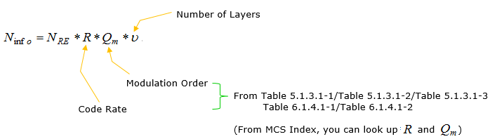
Step 1 : Read MCS from DCI and determin Qm (Modulation Scheme) and R(Code Rate) from following tables
-
38.214-Table 5.1.3.1-1
-
38.214-Table 5.1.3.1-2
-
38.214-Table 5.1.3.1-3
NOTE : The problem is to figure out which of the above tables to be applied. This is a pretty complicated and confusing procedure to pick up a specific table. I summerized this table picking criteria here.
Step 2 : Read RV(Redundancy Version) from DCI
Step 3 : Determine TBS (Transport block Size) based on following factors
-
Number of Layers
-
Number of PRB
PDSCH Transport Block Size Determination
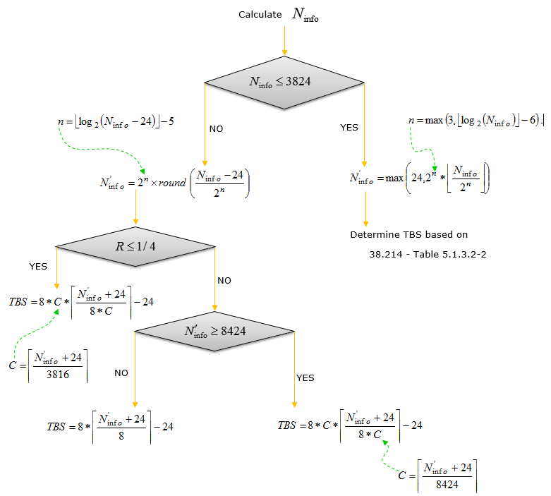
NR MCS and Code Rate are determined by a predefined table as in 38.214 - Table 5.1.3.1-1 and 38.214 - Table 5.1.3.1-2, which is pretty straight forward. However, determining TBS (Transport block size) in NR is more complicated than the one in LTE. In case of LTE, all the possibility of RBS are precalculated and listed as a big table. However, in NR the TBS determination process is described as a sequence of algorithm as summarized below (I think it will take a while to get familiar with this process).
< Calculate N_info >
As you see in the process illustrated above, the initial input for this algorithm is Ninfo. However, to figure out this Ninfo also requires long calculation process as below.

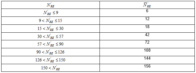
< 38.214 - Table 5.1.3.2-1: Quantized number of REs allocated for PDSCH within a PRB >
< 38.214 - Table 5.1.3.1-1: MCS index table 1 for PDSCH >
|
MCS Index IMCS |
Modulation Order Qm |
Target code Rate x [1024] R |
Spectral efficiency |
|
0 |
2 |
120 |
0.2344 |
|
1 |
2 |
157 |
0.3066 |
|
2 |
2 |
193 |
0.3770 |
|
3 |
2 |
251 |
0.4902 |
|
4 |
2 |
308 |
0.6016 |
|
5 |
2 |
379 |
0.7402 |
|
6 |
2 |
449 |
0.8770 |
|
7 |
2 |
526 |
1.0273 |
|
8 |
2 |
602 |
1.1758 |
|
9 |
2 |
679 |
1.3262 |
|
10 |
4 |
340 |
1.3281 |
|
11 |
4 |
378 |
1.4766 |
|
12 |
4 |
434 |
1.6953 |
|
13 |
4 |
490 |
1.9141 |
|
14 |
4 |
553 |
2.1602 |
|
15 |
4 |
616 |
2.4063 |
|
16 |
4 |
658 |
2.5703 |
|
17 |
6 |
438 |
2.5664 |
|
18 |
6 |
466 |
2.7305 |
|
19 |
6 |
517 |
3.0293 |
|
20 |
6 |
567 |
3.3223 |
|
21 |
6 |
616 |
3.6094 |
|
22 |
6 |
666 |
3.9023 |
|
23 |
6 |
719 |
4.2129 |
|
24 |
6 |
772 |
4.5234 |
|
25 |
6 |
822 |
4.8164 |
|
26 |
6 |
873 |
5.1152 |
|
27 |
6 |
910 |
5.3320 |
|
28 |
6 |
948 |
5.5547 |
|
29 |
2 |
reserved |
|
|
30 |
4 |
reserved |
|
|
31 |
6 |
reserved |
|
< 38.214 - Table 5.1.3.1-2: MCS index table 2 for PDSCH >
|
MCS Index IMCS |
Modulation Order Qm |
Target code Rate x [1024] R |
Spectral efficiency |
|
0 |
2 |
120 |
0.2344 |
|
1 |
2 |
193 |
0.377 |
|
2 |
2 |
308 |
0.6016 |
|
3 |
2 |
449 |
0.877 |
|
4 |
2 |
602 |
1.1758 |
|
5 |
4 |
378 |
1.4766 |
|
6 |
4 |
434 |
1.6953 |
|
7 |
4 |
490 |
1.9141 |
|
8 |
4 |
553 |
2.1602 |
|
9 |
4 |
616 |
2.4063 |
|
10 |
4 |
658 |
2.5703 |
|
11 |
6 |
466 |
2.7305 |
|
12 |
6 |
517 |
3.0293 |
|
13 |
6 |
567 |
3.3223 |
|
14 |
6 |
616 |
3.6094 |
|
15 |
6 |
666 |
3.9023 |
|
16 |
6 |
719 |
4.2129 |
|
17 |
6 |
772 |
4.5234 |
|
18 |
6 |
822 |
4.8164 |
|
19 |
6 |
873 |
5.1152 |
|
20 |
8 |
682.5 |
5.332 |
|
21 |
8 |
711 |
5.5547 |
|
22 |
8 |
754 |
5.8906 |
|
23 |
8 |
797 |
6.2266 |
|
24 |
8 |
841 |
6.5703 |
|
25 |
8 |
885 |
6.9141 |
|
26 |
8 |
916.5 |
7.1602 |
|
27 |
8 |
948 |
7.4063 |
|
28 |
2 |
reserved |
|
|
29 |
4 |
reserved |
|
|
30 |
6 |
reserved |
|
|
31 |
8 |
reserved |
|
< 38.214 - Table 5.1.3.1-3: MCS index table 3 for PDSCH >
|
MCS Index IMCS |
Modulation Order Qm |
Target code Rate x [1024] R |
Spectral efficiency |
|
0 |
2 |
30 |
0.0586 |
|
1 |
2 |
40 |
0.0781 |
|
2 |
2 |
50 |
0.0977 |
|
3 |
2 |
64 |
0.1250 |
|
4 |
2 |
78 |
0.1523 |
|
5 |
2 |
99 |
0.1934 |
|
6 |
2 |
120 |
0.2344 |
|
7 |
2 |
157 |
0.3066 |
|
8 |
2 |
193 |
0.3770 |
|
9 |
2 |
251 |
0.4902 |
|
10 |
2 |
308 |
0.6016 |
|
11 |
2 |
379 |
0.7402 |
|
12 |
2 |
449 |
0.8770 |
|
13 |
2 |
526 |
1.0273 |
|
14 |
2 |
602 |
1.1758 |
|
15 |
4 |
340 |
1.3281 |
|
16 |
4 |
378 |
1.4766 |
|
17 |
4 |
434 |
1.6953 |
|
18 |
4 |
490 |
1.9141 |
|
19 |
4 |
553 |
2.1602 |
|
20 |
4 |
616 |
2.4063 |
|
21 |
6 |
438 |
2.5664 |
|
22 |
6 |
466 |
2.7305 |
|
23 |
6 |
517 |
3.0293 |
|
24 |
6 |
567 |
3.3223 |
|
25 |
6 |
616 |
3.6094 |
|
26 |
6 |
666 |
3.9023 |
|
27 |
6 |
719 |
4.2129 |
|
28 |
6 |
772 |
4.5234 |
|
29 |
2 |
reserved |
|
|
30 |
4 |
reserved |
|
|
31 |
6 |
reserved |
|
< 38.214 - Table 5.1.3.2-1: TBS for N_info <= 3824 >
|
Index |
TBS |
Index |
TBS |
Index |
TBS |
Index |
TBS |
|
1 |
24 |
31 |
336 |
61 |
1288 |
91 |
3624 |
|
2 |
32 |
32 |
352 |
62 |
1320 |
92 |
3752 |
|
3 |
40 |
33 |
368 |
63 |
1352 |
93 |
3824 |
|
4 |
48 |
34 |
384 |
64 |
1416 |
|
|
|
5 |
56 |
35 |
408 |
65 |
1480 |
|
|
|
6 |
64 |
36 |
432 |
66 |
1544 |
|
|
|
7 |
72 |
37 |
456 |
67 |
1608 |
|
|
|
8 |
80 |
38 |
480 |
68 |
1672 |
|
|
|
9 |
88 |
39 |
504 |
69 |
1736 |
|
|
|
10 |
96 |
40 |
528 |
70 |
1800 |
|
|
|
11 |
104 |
41 |
552 |
71 |
1864 |
|
|
|
12 |
112 |
42 |
576 |
72 |
1928 |
|
|
|
13 |
120 |
43 |
608 |
73 |
2024 |
|
|
|
14 |
128 |
44 |
640 |
74 |
2088 |
|
|
|
15 |
136 |
45 |
672 |
75 |
2152 |
|
|
|
16 |
144 |
46 |
704 |
76 |
2216 |
|
|
|
17 |
152 |
47 |
736 |
77 |
2280 |
|
|
|
18 |
160 |
48 |
768 |
78 |
2408 |
|
|
|
19 |
168 |
49 |
808 |
79 |
2472 |
|
|
|
20 |
176 |
50 |
848 |
80 |
2536 |
|
|
|
21 |
184 |
51 |
888 |
81 |
2600 |
|
|
|
22 |
192 |
52 |
928 |
82 |
2664 |
|
|
|
23 |
208 |
53 |
984 |
83 |
2728 |
|
|
|
24 |
224 |
54 |
1032 |
84 |
2792 |
|
|
|
25 |
240 |
55 |
1064 |
85 |
2856 |
|
|
|
26 |
256 |
56 |
1128 |
86 |
2976 |
|
|
|
27 |
272 |
57 |
1160 |
87 |
3104 |
|
|
|
28 |
288 |
58 |
1192 |
88 |
3240 |
|
|
|
29 |
304 |
59 |
1224 |
89 |
3368 |
|
|
|
30 |
320 |
60 |
1256 |
90 |
3496 |
|
|
This is an illustration based on 38.214 - 5.1.3.2 Transport block size determination.
PUSCH Transport Block Size Determination
PUSCH Transport block size is influenced by RRC Parameters at the stage of determining Modulation Order and Code Rate and this makes it so difficult and complicated to understand the whole process of TBS(Transport Size) Determination. The RRC parameters involved in this process is highlighted in red as shown below.
38.331 15.3 (2018-10)
PUSCH-Config ::= SEQUENCE {
dataScramblingIdentityPUSCH INTEGER (0..1023) OPTIONAL,
txConfig ENUMERATED {codebook, nonCodebook}
dmrs-UplinkForPUSCH-MappingTypeA SetupRelease { DMRS-UplinkConfig }
dmrs-UplinkForPUSCH-MappingTypeB SetupRelease { DMRS-UplinkConfig }
pusch-PowerControl PUSCH-PowerControl
frequencyHopping ENUMERATED {intraSlot, interSlot}
frequencyHoppingOffsetLists SEQUENCE (SIZE (1..4)) OF
INTEGER (1.. maxNrofPhysicalResourceBlocks-1)
resourceAllocation ENUMERATED { resourceAllocationType0,
resourceAllocationType1,
dynamicSwitch},
pusch-TimeDomainAllocationList SetupRelease {
PUSCH-TimeDomainResourceAllocationList
}
pusch-AggregationFactor ENUMERATED { n2, n4, n8 }
mcs-Table ENUMERATED {qam256, qam64LowSE}
mcs-TableTransformPrecoder ENUMERATED {qam256, qam64LowSE}
transformPrecoder ENUMERATED {enabled, disabled}
codebookSubset ENUMERATED {fullyAndPartialAndNonCoherent,
partialAndNonCoherent,
nonCoherent}
maxRank INTEGER (1..4)
rbg-Size ENUMERATED { config2}
uci-OnPUSCH SetupRelease { UCI-OnPUSCH }
tp-pi2BPSK ENUMERATED {enabled}
...
}
ConfiguredGrantConfig ::= SEQUENCE {
frequencyHopping ENUMERATED {intraSlot, interSlot} ,
cg-DMRS-Configuration DMRS-UplinkConfig,
mcs-Table ENUMERATED {qam256, qam64LowSE}
mcs-TableTransformPrecoder ENUMERATED {qam256, qam64LowSE}
uci-OnPUSCH SetupRelease { CG-UCI-OnPUSCH } OPTIONAL,
resourceAllocation ENUMERATED { resourceAllocationType0,
resourceAllocationType1,
dynamicSwitch },
rbg-Size ENUMERATED {config2},
powerControlLoopToUse ENUMERATED {n0, n1},
p0-PUSCH-Alpha P0-PUSCH-AlphaSetId,
transformPrecoder ENUMERATED {enabled, disabled},
nrofHARQ-Processes INTEGER(1..16),
repK ENUMERATED {n1, n2, n4, n8},
repK-RV ENUMERATED {s1-0231, s2-0303, s3-0000},
periodicity ENUMERATED {
sym2, sym7, sym1x14, sym2x14, sym4x14,
sym5x14, sym8x14, sym10x14, sym16x14,
sym20x14,sym32x14, sym40x14, sym64x14,
sym80x14, sym128x14, sym160x14, sym256x14,
sym320x14, sym512x14,sym640x14, sym1024x14,
sym1280x14, sym2560x14, sym5120x14,sym6,
sym1x12, sym2x12, sym4x12, sym5x12,
sym8x12, sym10x12, sym16x12, sym20x12,
sym32x12,sym40x12, sym64x12, sym80x12,
sym128x12, sym160x12, sym256x12, sym320x12,
sym512x12, sym640x12,sym1280x12, sym2560x12
},
configuredGrantTimer INTEGER (1..64) OPTIONAL, -- Need R
rrc-ConfiguredUplinkGrant SEQUENCE {
timeDomainOffset INTEGER (0..5119),
timeDomainAllocation INTEGER (0..15),
frequencyDomainAllocation BIT STRING (SIZE(18)),
antennaPort INTEGER (0..31),
dmrs-SeqInitialization INTEGER (0..1),
precodingAndNumberOfLayers INTEGER (0..63),
srs-ResourceIndicator INTEGER (0..15),
mcsAndTBS INTEGER (0..31),
frequencyHoppingOffset
INTEGER (1.. maxNrofPhysicalResourceBlocks-1)
pathlossReferenceIndex
INTEGER (0..maxNrofPUSCH-PathlossReferenceRSs-1)
...
} OPTIONAL, -- Need R
...
}
< Modulation order and target code rate determination >
I created following table based on the descriptions in 28.214-6.1.4.1(v15.3 - Oct 2018).
|
Transform Precoding |
mcs-Table |
mcs-Table TransformPrecoder |
RNTI |
DCI |
MCS Index Table |
||
|
PUSCH-Config |
Configured GrantConfig |
PUSCH-Config |
Configured GrantConfig |
||||
|
diabled |
qam256 |
N/A |
N/A |
C-RNTI SP-CSI-RNTI |
0_1 |
||
|
diabled |
qam64LowSE |
N/A |
N/A |
NOT MCS-C-RNTI C-RNTI SP-CSI-RNTI |
|
||
|
diabled |
N/A |
qam256 |
N/A |
MCS-C-RNT |
|
||
|
diabled |
N/A |
qam64LowSE |
N/A |
CS-RNTI |
|
||
|
diabled |
none of the above |
||||||
|
enabled |
qam256 |
|
|
C-RNTI SP-CSI-RNTI |
0_1 |
||
|
enabled |
qam64LowSE |
|
|
NOT MCS-C-RNTI C-RNTI SP-CSI-RNTI |
|
6.1.4.1-2 |
|
|
enabled |
|
|
|
MCS-C-RNT |
|
6.1.4.1-2 |
|
|
enabled |
|
qam256 |
|
CS-RNTI |
|
||
|
enabled |
|
qam64LowSE |
|
CS-RNTI |
|
6.1.4.1-2 |
|
|
enabled |
none of the above |
6.1.4.1-1 |
|||||
< Transport block size determination >
I created following summary based on the descriptions in 28.214-6.1.4.2 (v15.3 - Oct 2018).
Case 1 : I_MCS is NOT in 'reserved' range.
NOTE : The condition for this case is described in 28.214-6.1.4.2 (v15.3 - Oct 2018) as follows. At first, it looks very confusing. It looked like three different 'if statement' with conflicting condition. But looking more closely, I realized all of these three lines makes up a single 'if statement'. You see all of these three lines are combined by 'or'.
- 0 <= I_MCS <≤ 27 and transform precoding is disabled and Table 5.1.3.1-2 is used, or
- 0 <≤ I_MCS <≤ 28 and transform precoding is disabled and a table other than Table 5.1.3.1-2 is used, or
- 0 <≤ I_MCS <≤ 27 and transform precoding is enabled
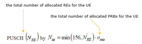
First Calculate N'_RE using following formula

Next Calculate the total number of REs for PUSCH as follows.
Next Calculate Ninfo as follows :
Next step is same as downlink TBS determination process as shown below.
Case 2 : I_MCS is in 'reserved' range.
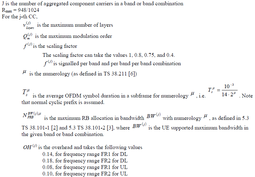
As per 38.306-4.1.2, the max throughput can be estimated as follows.

Reference
[1]