5G/NR - PDSCH DMRS Home : www.sharetechnote.com
PDSCH DMRS(DeModulation Reference Signal)
PDSCH DMRS is a special type of physical layer signal which functions as a reference signal for decoding PDSCH. In LTE (at least in TM1, 2, 3, 4), we don't need this kind of special DMRS for PDSCH because we can use CRS(Cell Specific Reference Signal) for PDSCH decoding. However, in 5G/NR there is no CRS. That's why we need the DMRS dedicated for PDSCH decoding.
- Basic Questions
- Parameters and Examples
- Sequence Generation
- Resource Element Mapping
- Tables
- Table 7.4.1.1.2-1: Parameters for PDSCH DM-RS configuration type 1
- Table 7.4.1.1.2-2: Parameters for PDSCH DM-RS configuration type 2
- Table 7.4.1.1.2-3: PDSCH DM-RS positions l bar for single-symbol DM-RS
- Table 7.4.1.1.2-4: PDSCH DM-RS positions l bar for double-symbol DM-RS
- Table 7.4.1.1.2-5: PDSCH DM-RS time index l' and antenna ports p
DMRS configuration sometimes is pretty confusing unless you have some type of big picture. If you frequently refresh yourself with the following questions, it will be helpful when you read further details in this page.
What is the difference between Mapping Type A and B in terms of resource allocation ?
Type A can start only at symbol 2 or 3 within a slot, meaning that SLIV that start from symbol 4 or higher cannot use this type of DMRS.
Type B starts always at the first symbols of scheduled SLIV.
What is the difference between configuration type 1 and 2 in terms of resource allocation ?
In Configuration type 1, the minimum resource element group in frequency domain is one RE. In Configuration type 2, the minimum resource element group in frequency domain is two consecutive REs. See the pictures in Resource Element Mapping.
What is the effect of port number on DMRS resource element position ?
As antenna port number changes, the location of DMRS position in frequency domain changes. See examples in < Type A > and < Type B > section.
How many DMRS symbol can be put into a slot ?
Minimum number is 1, but it can be more than 1 depending on dmrs-AdditionalPosition in RRC. Max number is 4. See 38.211 - Table 7.4.1.1.2-3 and 38.211 - Table 7.4.1.1.2-4 for the details.
|
38.211-7.4.1.1 |
Higher Layer Parameter |
Value |
Comment |
|
|
DL-DMRS-Scrambling-ID |
{0,1} |
Sequence Generation |
|
|
DL-DMRS-Scrambling-ID |
{0,1,..,65535} |
Sequence Generation |
|
Configuration Type |
DL-DMRS-config-type dmrs-Type |
type1, type2 |
RE Mapping |
|
|
DL-DMRS-typeA-pos dmrs-TypeA-Position |
pos2, pos3 |
RE Mapping |
|
|
DL-DMRS-add-pos dmrs-AdditionalPosition |
pos0, pos1, pos2, pos3 |
RE Mapping |
|
|
DL-DMRS-max-len |
|
RE Mapping |
|
single or double symbol |
|
|
RE Mapping |
MIB ::= SEQUENCE {
...
dmrs-TypeA-Position ENUMERATED {pos2, pos3},
...
}
PDSCH-TimeDomainResourceAllocation ::= SEQUENCE {
k0 INTEGER (1..3)
mappingType ENUMERATED {typeA, typeB},
startSymbolAndLength BIT STRING (SIZE (7))
}
k0 : Corresponds to L1 parameter 'K0'. When the field is absent the UE applies the value 0
mappingType : PDSCH mapping type. Corresponds to L1 parameter 'Mapping-type' (See SLIV page)
startSymbolAndLength : An index into a table/equation in RAN1 specs capturing valid combinations of start symbol and length (jointly encoded). Corresponds to L1 parameter 'Index-start-len' (See SLIV page)
PDSCH-Config ::= SEQUENCE {
...
dmrs-DownlinkForPDSCH-MappingTypeA SetupRelease { DMRS-DownlinkConfig }
dmrs-DownlinkForPDSCH-MappingTypeB SetupRelease { DMRS-DownlinkConfig }
...
}
DMRS-DownlinkConfig ::= SEQUENCE {
dmrs-Type ENUMERATED {type2} OPTIONAL, -- Need R
dmrs-AdditionalPosition ENUMERATED {pos0, pos1, pos3} OPTIONAL, -- Need R
dmrs-group1 BIT STRING (SIZE (12)) OPTIONAL, -- Need R
dmrs-group2 BIT STRING (SIZE (12)) OPTIONAL, -- Need R
maxLength ENUMERATED {len2} OPTIONAL, -- Need R
scramblingID0 INTEGER (0..65535) OPTIONAL, -- Need S
scramblingID1 INTEGER (0..65535) OPTIONAL, -- Need S
phaseTrackingRS SetupRelease { PTRS-DownlinkConfig } OPTIONAL, -- Need M
...
}
PTRS-DownlinkConfig ::= SEQUENCE {
frequencyDensity SEQUENCE (SIZE (2)) OF INTEGER (1..276) OPTIONAL, -- Need S
timeDensity SEQUENCE (SIZE (3)) OF INTEGER (0..29) OPTIONAL, -- Need S
epre-Ratio INTEGER (0..3) OPTIONAL, -- Need S
resourceElementOffset ENUMERATED { offset01, offset10, offset11 } OPTIONAL, -- Need S
...
}
dmrs-Type : Selection of the DMRS type to be used for DL. If the field is absent, the UE uses DMRS type 1.
dmrs-AdditionalPosition : Position for additional DM-RS in DL. The four values represent the cases of 1+0, 1+1, 1+1+1. 1+1+1+1 non-adjacent OFDM symbols for DL. If the field is absent, the UE applies the value pos2.
dmrs-group1 : DM-RS groups that are QCL:ed, i.e. group 1
dmrs-group2 : DM-RS groups that are QCL:ed, i.e. group 2
maxLength : The maximum number of OFDM symbols for DL front loaded DMRS. 'len1' corresponds to value 1. 'len2 corresponds to value 2. If the field is absent, the UE applies value len1. Corresponds to L1 parameter 'DL-DMRS-max-len'
scramblingID0 : DL DMRS scrambling initalization. Corresponds to L1 parameter 'n_SCID 0'. When the field is absent the UE applies the value Physical cell ID (physCellId) configured for this serving cell
scramblingID1 : DL DMRS scrambling initalization. Corresponds to L1 parameter 'n_SCID 0'. When the field is absent the UE applies the value Physical cell ID (physCellId) configured for this serving cell
phaseTrackingRS : Configures downlink PTRS. If absent or released, the UE assumes that downlink PTRS are not present
It would be almost impossible for you to get the practical meaning of these parameters just by looking into the specification unless you are the person who designed this algorithm or create your own program to implement this specification and plot it in graphics. I am not the person who desgined the algorithm and I don't have my own program to implement it. So it was so difficult for me to get any intuitive understandings on these parameters and algorithm. Fortunately, I got a chance to try with Matlab 5G library. Followings are the examples in graphics that I created using Matlab 5G library. I posted Matlab code and more examples here. The subcarrier spacing used in this example is 30 Khz and for the simplicity I assigned only one RB for the PDSCH.
Look through these examples and try to get some intuitive pattern. If it is not easy for you to see any pattern, refer to Resource Element Mapping section first and then get back to these examples.
NOTE : The RE(Resource Element) number in frequency domain of these examples starts from '1', but in 3GPP the RE number within a RB starts from '0'.
|
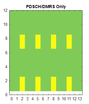
Number of Layers = 1 Port = 1000; PDSCH Mapping Type = 'A'; dmrs-TypeA-Position = pos2; DL-DMRS-max-len = 1; dmrs-AdditionalPosition = pos0; dmrs-Type = type2; DL-DMRS-Scrambling-ID.NIDNSCID = 1; DL-DMRS-Scrambling-ID.NSCID = 0; |
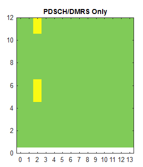
Number of Layers = 1 Port = 1000; PDSCH Mapping Type = 'A'; dmrs-TypeA-Position = pos3; DL-DMRS-max-len = 1; dmrs-AdditionalPosition = pos0; dmrs-Type = type2; DL-DMRS-Scrambling-ID.NIDNSCID = 1; DL-DMRS-Scrambling-ID.NSCID = 0; |
|
|
|
|
Number of Layers = 1 Port = 1000; PDSCH Mapping Type = 'A'; dmrs-TypeA-Position = pos2; DL-DMRS-max-len = 2; dmrs-AdditionalPosition = pos0; dmrs-Type = type2; DL-DMRS-Scrambling-ID.NIDNSCID = 1; DL-DMRS-Scrambling-ID.NSCID = 0; |
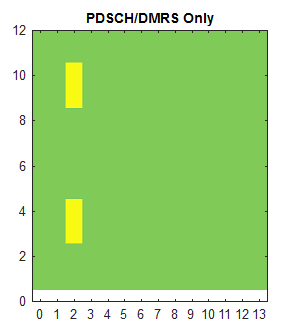
Number of Layers = 1 Port = 1000; PDSCH Mapping Type = 'A'; dmrs-TypeA-Position = pos2; DL-DMRS-max-len = 1; dmrs-AdditionalPosition = pos1; dmrs-Type = type2; DL-DMRS-Scrambling-ID.NIDNSCID = 1; DL-DMRS-Scrambling-ID.NSCID = 0; |
|
|
|
|
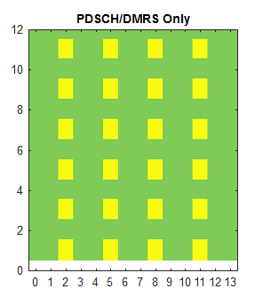
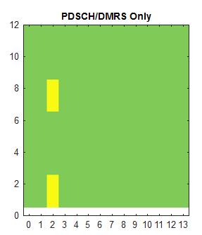
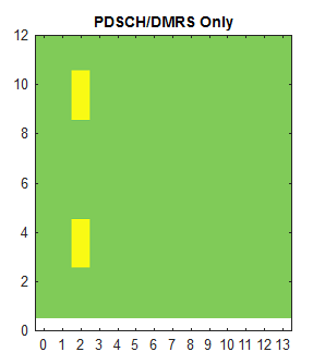
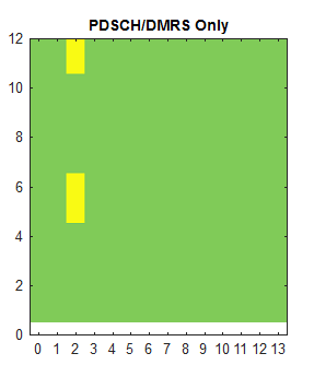
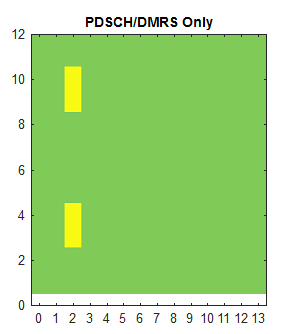
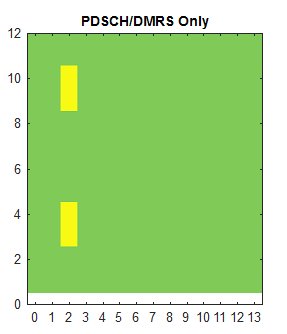
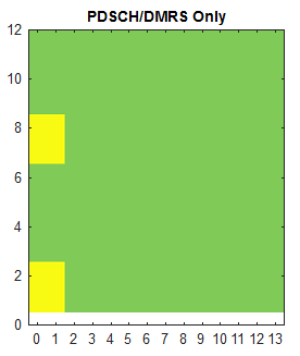
Number of Layers = 1 Port = 1000; PDSCH Mapping Type = 'A'; dmrs-TypeA-Position = pos2; DL-DMRS-max-len = 1; dmrs-AdditionalPosition = pos2; dmrs-Type = type2; DL-DMRS-Scrambling-ID.NIDNSCID = 1; DL-DMRS-Scrambling-ID.NSCID = 0; |
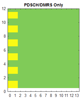
Number of Layers = 1 Port = 1000; PDSCH Mapping Type = 'A'; dmrs-TypeA-Position = pos2; DL-DMRS-max-len = 1; dmrs-AdditionalPosition = pos3; dmrs-Type = type2; DL-DMRS-Scrambling-ID.NIDNSCID = 1; DL-DMRS-Scrambling-ID.NSCID = 0; |
|
|
|
|
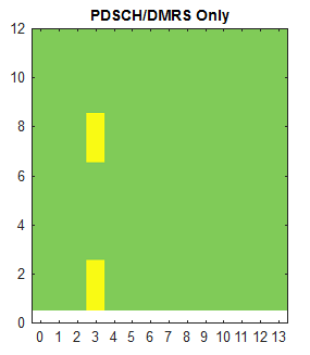
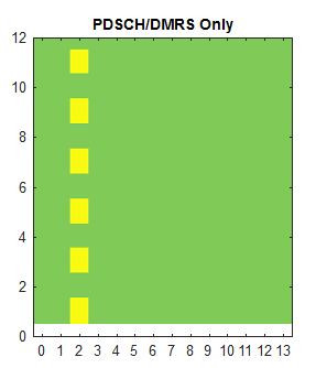
Number of Layers = 1 Port = 1000; PDSCH Mapping Type = 'A'; dmrs-TypeA-Position = pos2; DL-DMRS-max-len = 1; dmrs-AdditionalPosition = pos0; dmrs-Type = type1; DL-DMRS-Scrambling-ID.NIDNSCID = 1; DL-DMRS-Scrambling-ID.NSCID = 0; |
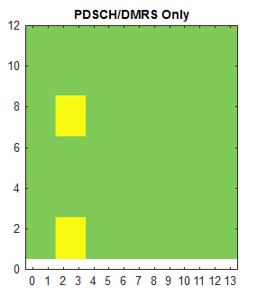
Number of Layers = 1 Port = 1000; PDSCH Mapping Type = 'A'; dmrs-TypeA-Position = pos2; DL-DMRS-max-len = 2; dmrs-AdditionalPosition = pos0; dmrs-Type = type1; DL-DMRS-Scrambling-ID.NIDNSCID = 1; DL-DMRS-Scrambling-ID.NSCID = 0; |
|
|
|
|
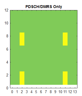
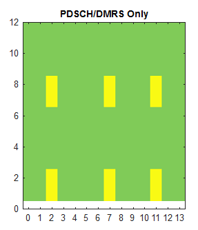
Number of Layers = 1 Port = 1000; PDSCH Mapping Type = 'A'; dmrs-TypeA-Position = pos2; DL-DMRS-max-len = 1; dmrs-AdditionalPosition = pos3; dmrs-Type = type1; DL-DMRS-Scrambling-ID.NIDNSCID = 1; DL-DMRS-Scrambling-ID.NSCID = 0; |
|
|
|
|
|
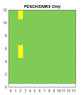
Number of Layers = 1 Port = 1000; PDSCH Mapping Type = 'A'; dmrs-TypeA-Position = pos2; DL-DMRS-max-len = 1; dmrs-AdditionalPosition = pos0; dmrs-Type = type2; DL-DMRS-Scrambling-ID.NIDNSCID = 1; DL-DMRS-Scrambling-ID.NSCID = 0; |
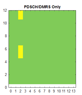
Number of Layers = 1 Port = 1001; PDSCH Mapping Type = 'A'; dmrs-TypeA-Position = pos2; DL-DMRS-max-len = 1; dmrs-AdditionalPosition = pos0; dmrs-Type = type2; DL-DMRS-Scrambling-ID.NIDNSCID = 1; DL-DMRS-Scrambling-ID.NSCID = 0; |
|
|
|
|
Number of Layers = 1 Port = 1002; PDSCH Mapping Type = 'A'; dmrs-TypeA-Position = pos2; DL-DMRS-max-len = 1; dmrs-AdditionalPosition = pos0; dmrs-Type = type2; DL-DMRS-Scrambling-ID.NIDNSCID = 1; DL-DMRS-Scrambling-ID.NSCID = 0; |
Number of Layers = 1 Port = 1003; PDSCH Mapping Type = 'A'; dmrs-TypeA-Position = pos2; DL-DMRS-max-len = 1; dmrs-AdditionalPosition = pos0; dmrs-Type = type2; DL-DMRS-Scrambling-ID.NIDNSCID = 1; DL-DMRS-Scrambling-ID.NSCID = 0; |
|
|
|
|
Number of Layers = 1 Port = 1004; PDSCH Mapping Type = 'A'; dmrs-TypeA-Position = pos2; DL-DMRS-max-len = 1; dmrs-AdditionalPosition = pos0; dmrs-Type = type2; DL-DMRS-Scrambling-ID.NIDNSCID = 1; DL-DMRS-Scrambling-ID.NSCID = 0; |
Number of Layers = 1 Port = 1005; PDSCH Mapping Type = 'A'; dmrs-TypeA-Position = pos2; DL-DMRS-max-len = 1; dmrs-AdditionalPosition = pos0; dmrs-Type = type2; DL-DMRS-Scrambling-ID.NIDNSCID = 1; DL-DMRS-Scrambling-ID.NSCID = 0; |
|
|
|
|
Number of Layers = 1 Port = 1006; PDSCH Mapping Type = 'A'; dmrs-TypeA-Position = pos2; DL-DMRS-max-len = 1; dmrs-AdditionalPosition = pos0; dmrs-Type = type2; DL-DMRS-Scrambling-ID.NIDNSCID = 1; DL-DMRS-Scrambling-ID.NSCID = 0; |
Number of Layers = 1 Port = 1007; PDSCH Mapping Type = 'A'; dmrs-TypeA-Position = pos2; DL-DMRS-max-len = 1; dmrs-AdditionalPosition = pos0; dmrs-Type = type2; DL-DMRS-Scrambling-ID.NIDNSCID = 1; DL-DMRS-Scrambling-ID.NSCID = 0; |
|
|
|
|
Number of Layers = 1 Port = 1008; PDSCH Mapping Type = 'A'; dmrs-TypeA-Position = pos2; DL-DMRS-max-len = 1; dmrs-AdditionalPosition = pos0; dmrs-Type = type2; DL-DMRS-Scrambling-ID.NIDNSCID = 1; DL-DMRS-Scrambling-ID.NSCID = 0; |
Number of Layers = 1 Port = 1009; PDSCH Mapping Type = 'A'; dmrs-TypeA-Position = pos2; DL-DMRS-max-len = 1; dmrs-AdditionalPosition = pos0; dmrs-Type = type2; DL-DMRS-Scrambling-ID.NIDNSCID = 1; DL-DMRS-Scrambling-ID.NSCID = 0; |
|
|
|
|
Number of Layers = 1 Port = 1010; PDSCH Mapping Type = 'A'; dmrs-TypeA-Position = pos2; DL-DMRS-max-len = 1; dmrs-AdditionalPosition = pos0; dmrs-Type = type2; DL-DMRS-Scrambling-ID.NIDNSCID = 1; DL-DMRS-Scrambling-ID.NSCID = 0; |
Number of Layers = 1 Port = 1011; PDSCH Mapping Type = 'A'; dmrs-TypeA-Position = pos2; DL-DMRS-max-len = 1; dmrs-AdditionalPosition = pos0; dmrs-Type = type2; DL-DMRS-Scrambling-ID.NIDNSCID = 1; DL-DMRS-Scrambling-ID.NSCID = 0; |
|
|
|

|
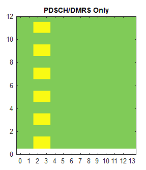
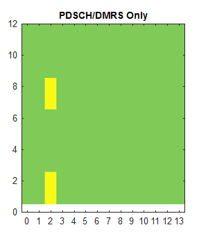
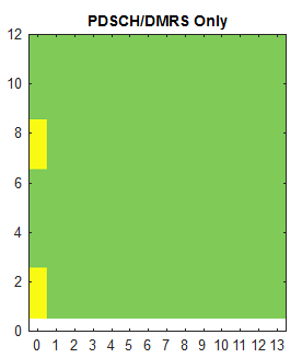
Number of Layers = 1 Port = 1000; PDSCH Mapping Type = 'B'; DL-DMRS-max-len = 1; dmrs-AdditionalPosition = pos0 dmrs-Type = type2; DL-DMRS-Scrambling-ID.NIDNSCID = 1; DL-DMRS-Scrambling-ID.NSCID = 0; |
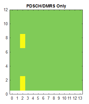
Number of Layers = 1 Port = 1000; PDSCH Mapping Type = 'B'; DL-DMRS-max-len = 2; dmrs-AdditionalPosition = pos0 dmrs-Type = type2; DL-DMRS-Scrambling-ID.NIDNSCID = 1; DL-DMRS-Scrambling-ID.NSCID = 0; |
|
|
|
|
Number of Layers = 1 Port = 1000; PDSCH Mapping Type = 'B'; DL-DMRS-max-len = 1; dmrs-AdditionalPosition = pos0 dmrs-Type = type1; DL-DMRS-Scrambling-ID.NIDNSCID = 1; DL-DMRS-Scrambling-ID.NSCID = 0; |
Number of Layers = 1 Port = 1000; PDSCH Mapping Type = 'B'; DL-DMRS-max-len = 2; dmrs-AdditionalPosition = pos0 dmrs-Type = type1; DL-DMRS-Scrambling-ID.NIDNSCID = 1; DL-DMRS-Scrambling-ID.NSCID = 0; |
|
|
|

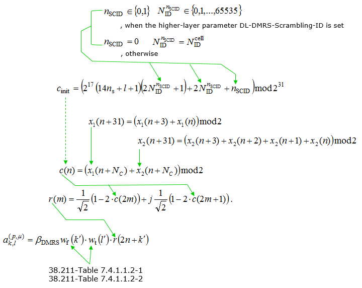
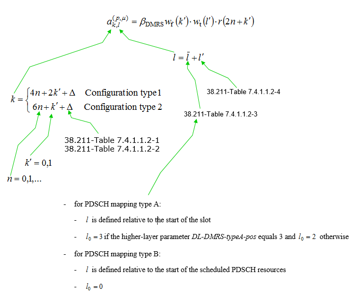
Resource Mapping of PDSCH DMRS is done as following equation. For simplicity, let's think of the location of resource element only (i.e, let's think only of k and l). k represents frequency domain location and l represents time domain location.
With this in mind, the first thing you can notice would be
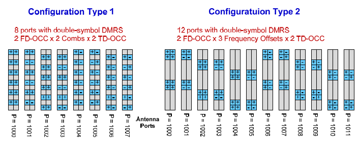
- Configuration type changes the location pattern in frequency domain
- Configurataion Type 1 : 3 pairs(6 Resource Elements:RE) of DMRS are dispersed in one OFDM symbol/one RB at the interval of 4 REs (4n). The two RE in each pare are apart at the interval of 2 RE(2k'). In short, 6 REs of DMRS symbols are dispersed at every other REs in frequency domain. This supports 8 DMRS ports in case of double-symbol DMRS(port 1000~1007) and 4 DMRS ports in case of single symbol DMRS(port 1000~1003). See Table 7.4.1.1.2-1 and Table 7.4.1.1.2-5 for further details.
- Configuration Type 2 : 2 pairs(4 Resource Elements:RE) of DMRS are dispersed in one OFDM symbol/one RB at the interval of 6 REs (6n). The two RE in each pare are apart at the interval of 1 RE(k'), meaning that the two REs in each pair are contiguous. This supports 12 DMRS ports in case of double-symbol DMRS(port 1000~1011) and 8 DMRS ports in case of single symbol DMRS(port 1000~1007). See Table 7.4.1.1.2-2 and Table 7.4.1.1.2-5 for further details.
- PDSCH mapping type changes the location pattern in time domain
- PDSCH Mapping Type A : In this type, the DMRS symbol can start only at symbol 2 or 3 regardless of PDSCH start and length. It implies this cannot be used when PDSCH start symbol is greater than 3. This is related to the row 'Type A' in PDSCH SLIV table. This type is used for slot based scheduling.
- PDSCH Mapping Type B : In this type, the DMRS symbol can start at the first PDSCH symbol regardless of PDSCH start. This is related to the row 'Type B' in PDSCH SLIV table. This type is used for mini-slot based scheduling
Another points you would notice would be
- frequency domain location(k) is determined by equation(formula) as shown below
- time domain location(l) is determined by a predefined table and predefined value.
The result of this equation is well summarized by Ref [1] as shown below. If you really want to understand the details of this equation, fill out the resource grid on your own by hand. Since this is simple formula, you would be able to calculate the position of this DMRS RE by hand.
Followings are various tables that are used in Sequence Generation and Resource Element Mappaing shown above.
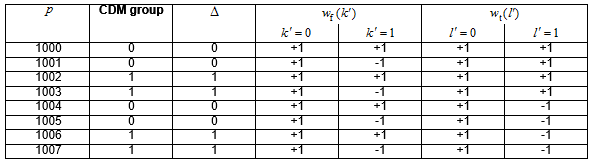
< 38.211 - Table 7.4.1.1.2-1: Parameters for PDSCH DM-RS configuration type 1 >
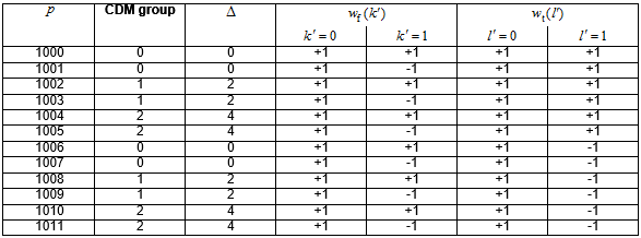
< 38.211 - Table 7.4.1.1.2-2: Parameters for PDSCH DM-RS configuration type 2 >
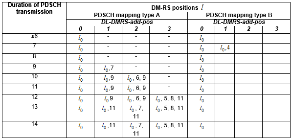
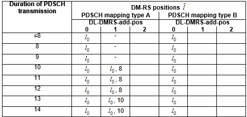
< 38.211 - Table 7.4.1.1.2-3: PDSCH DM-RS positions ![]() for single-symbol DM-RS >
for single-symbol DM-RS >
This table shows how the location of single symbol DMRS(i.e, maxlength = 1) is determined for each PDSCH mapping type. It shows that for mapping type B there is only one case where additional dmrs can be used. It is when the length of PDSCH is 7 symbols. For mapping type A, one additional dmrs can be used when PDSCH symbol length is equal to or greather than 9, two additional dmrs can be used when PDSCH symbol length is equal to or greather than 10 and three additional dmrs can be used when PDSCH symbol length is equal to or greather than 12.
< 38.211 - Table 7.4.1.1.2-4: PDSCH DM-RS positions ![]() for double-symbol DM-RS >
for double-symbol DM-RS >
This table shows how the location of double symbol DMRS(i.e, maxlength = 2) is determined for each PDSCH mapping type. It shows that for mapping type B additional dmrs cannot be used. For mapping type A, only one additional dmrs can be used when PDSCH symbol length is equal to or greather than 10. Regardless of mapping type, 2 additional dmrs cannot be used.
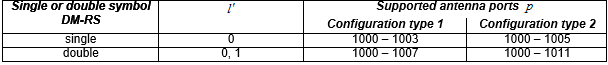
< 38.211 -Table 7.4.1.1.2-5: PDSCH DM-RS time index l' and antenna ports p >
This table shows how many DMRS antenna port can be used for each DMRS configuration (i.e, Configuration type and max length of DMRS symbols). As shown here, when the max dmrs symbol lengh is 1, maximum 4 dmrs antenna ports can be used for configuration type 1 and max 6 dmrs port can be used for configuration type 2. When the max dmrs symbol length is 2, 8 dmrs antenna port can be used for configuration type 1 and 12 dmrs antenna port can be used for configuration type 2.
This information is used to select which Antenna port table is associated in DCI 1_1 for setting up SISO/MIMO
Reference
[1] Wireless Technology Evolution - Transition from 4G to 5G : 5G Americas