There are roughly three different types of UL transmission scheme : not-configured, codebook based and non-codebook based. This scheme is determined by a RRC paramter txConfig.
- Parameters for Transmission Mode Determination
- Determination of W matrix
- Case 1 : txConfig in RRC = Non-codebook
- Case 2 : txConfig in RRC = codebook
- Case 3 : txConfig in RRC Not configured
- NonCodebook based Transmission
- Codebook based Transmission
- Codebook vs Non-Codebook based Transmission
- UE capability report vs applicable codebookSubset
- Number of configurable SRS
- txConfig and DCI type
- RRC Parameters
- Tables / Codebook
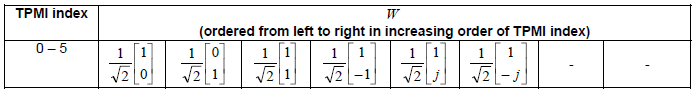
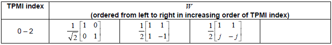
- Precoding matrix W for single-layer transmission using two antenna ports.
- Precoding matrix W for single-layer transmission using four antenna ports with transform precoding enabled.
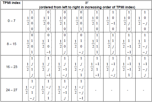
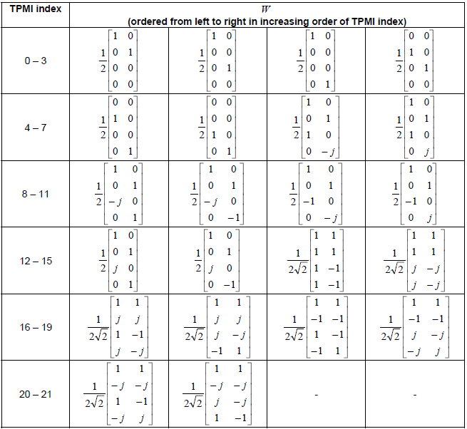
- Precoding matrix W for single-layer transmission using four antenna ports with transform precoding disabled.
- Precoding matrix W for two-layer transmission using two antenna ports with transform precoding disabled
- Precoding matrix W for two-layer transmission using four antenna ports with transform precoding disabled
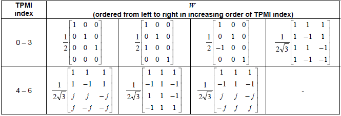
- Precoding matrix W for three-layer transmission using four antenna ports with transform precoding disabled.
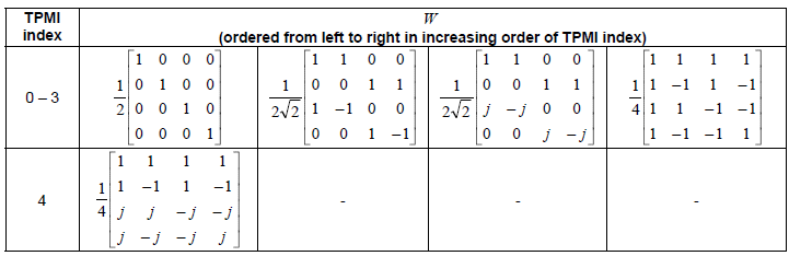
- Precoding matrix W for four-layer transmission using four antenna ports with transform precoding disabled
Parameters for Transmission Mode Determination
Followings are the major factors (configuration) to determine the PUSCH Transmission Mode and Precoding Matrix. Depending on the combinations (permutations) of these parameters, a specific transmission mode/precoding matrix is determined, but the detailed procedure is pretty complicated (confusing to me). Basically most of this page is all about how a specific transmission mode/precoding matrix is determined by combination of these three parameters.
Good thing would be that the precoding matrix is always 1 or Identity Matrix when the number of layer is 1. I think (hope) the number of UL layer would ramain as 1 for a long time -:).
![]()
Determination of W matrix
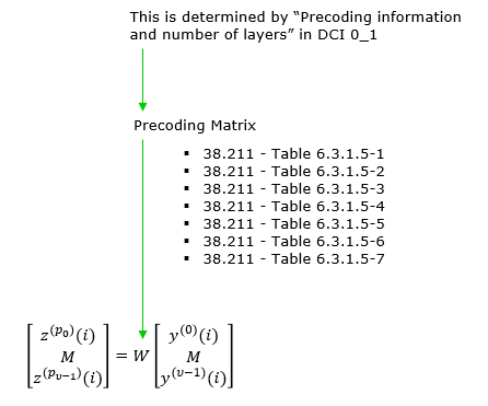
Basically PUSCH transmission mode is a parameter that determines Precoding matrix during the PUSCH channel processing(See here for the Precoding step in the whole PUSCH transport process) and the transmission mode is determined by several factors in RRC as shown below. Simply put, this is all about determining W matrix in following equation.
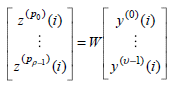
According to 38.211 - 6.3.1.5, we can determine W matrix as follows.
Case 1 : txConfig in RRC = Non-codebook
W = Identity Matrix
Case 2 : txConfig in RRC = codebook
When number of layer = 1, number of antenna port = 1
W = 1
When number of layer >= 2 and number of antenna port >=2 (See Codebook based transmission for details)
The Precoding matrix is determined by the number of layers and physical antenna, and Transform Precoding as summarized below.
|
Number of Layers |
Number of Antenna |
Transform Precoding |
Precoding Matrix |
|
1 |
2 |
|
|
|
1 |
4 |
enabled |
|
|
1 |
4 |
disabled |
|
|
2 |
2 |
disabled |
|
|
2 |
4 |
disabled |
|
|
3 |
4 |
disabled |
|
|
4 |
4 |
disabled |
Case 3 : txConfig in RRC : Not configured
W = 1
NonCodebook based Transmission
Non-codebook based UL transmission in mobile communication refers to a method where the UE determines its transmission strategy without relying on a predefined codebook. The precoder is determined directly from measurements by the UE rather than from an indicated codebook/TPMI index. In this mode, UE calculate Precoder matrix as follows (based on 38.214-6.1.1.2)
-
the UE determines the precoder(s) and rank based on one or two SRI fields in the DCI.
-
These point to one or two SRS resources Sets configured by higher layers.
-
Only one SRS port per SRS resource can be configured.
-
The UE can calculate the SRS precoder based on measurements of an associated NZP CSI-RS resource:
-
For aperiodic SRS, the NZP CSI-RS is indicated in the SRS request field of the DCI. The association between SRS Resource Sets and NZP CSI-RS resources is configured by higher layers.
-
For periodic/semi-persistent SRS, the associated NZP CSI-RS resource is configured by higher layers.
- The UE calculates the precoder for SRS transmission based on the measurement of an associated NZP CSI-RS resource.
- Different configurations (aperiodic, periodic, semi-persistent) dictate how the NZP-CSI-RS resources and SRS resource sets are associated and triggered
-
The UE maps the SRI(s) to DM-RS ports in increasing order and transmits the PUSCH using the same antenna ports as the indicated SRS resources. The UE maps SRIs to DM-RS ports and corresponding PUSCH layers, transmitting PUSCH using the same antenna ports as the SRS ports indicated by SRIs.
i) figure out "SRS Resource Indicator" in DCI_0_0, DCI 0_1 and semistatically ( srs-ResourceIndicator in RRC if configured)
ii) figure out wideband SRI based on step i)
iii) figure out transmission rank and PUSCH Precoder
Codebook based Transmission
Codebook-based UL transmission in mobile communications involves a method where the UE determines its transmission strategy using a predefined set of precoding vectors, known as a codebook. Codebook based UL transmission relies on an indicated SRS resource to determine the codebook, and TPMI values to indicate which precoder to use from that codebook for the transmission. The number of layers is also indicated. In this mode, the precoding matrix is determined as follows (based on 38.214-6.1.1.1).
- Codebook Subset(PUSCH-Config.codebookSubset)
- Number of Antenna Ports
- PUSCH Transform Precoding(PUSCH-Config.transformPrecoder)
- PUSCH Max Rank (PUSCH-Config.maxRank)
- DMRS Config Type (DMRS-UplinkConfig.dmrs-Type)
- UL PTRS Configuration (PUSCH-Config.DMRS-UplinkConfig.PTRS-UplinkConfig)
-
Codebook Subsets:
-
The UE determines its codebook subsets based on TPMIs and the reception of the higher layer parameter codebookSubset in pusch-Config.
-
Transmission Rank and Power Transmission:
-
The maximum transmission rank may be set by the higher layer parameter maxRank in pusch-Config.
-
Different configurations and UE capabilities influence whether the transmission is fullyAndPartialAndNonCoherent, partialAndNonCoherent, or nonCoherent.
-
Antenna Port Usage:
-
The UE transmits PUSCH using the same antenna ports as the SRS ports indicated in the DCI format or configuredGrantConfig as per 38.214-6.1.2.3.
-
DM-RS Antenna Ports:
-
The DM-RS antenna ports are determined according to the ordering of DM-RS ports in 38.212.
i) figure out "SRS Resource Indicator(SRI)" and "Precoding information(TMPI) and number of layers" in DCI 0_1
ii) figure out following settings
iii) Select a specific TPMI table using all the information from step i) and ii), and the mapping tables summarized as below.
iv) Figure out TPMI from the selected table (Further details are as follows)
Codebook vs Non-Codebook based Transmission
Following is a comparative table between Codebook vs Non-Codebook based UL Transmission
|
Parameter |
Codebook Based |
Non-Codebook Based |
|---|---|---|
|
Precoder Determination |
Based on SRS-ResourceSet configuration which determines codebook, and indicated TPMI index choosing precoder from codebook |
Based on measurements of indicated SRS/CSI-RS resources |
|
Scheduling Options |
DCI formats 0_0, 0_1, 0_2 or semi-static configuration |
DCI formats 0_0, 0_1, 0_2 or semi-static configuration |
|
Rank Determination |
Indicated in number of layers field in DCI |
Determined from measurements by UE |
|
Number of Configured SRS Resources |
Up to 2 (4 in fullpowerMode2) |
Up to 4 |
|
DCI Contents |
SRS Resource Indicator (SRI) and Precoding and Number of Layers (TPMI + rank) |
SRS Resource Indicator (SRI) only |
|
UE Processing |
Applies configured codebook subset; uses TPMI to select precoder |
Calculates precoder from measurements |
|
Transmission Ports |
Same ports as indicated SRS resource |
Same ports as indicated SRS resource |
|
Codebook Configuration |
Codebook subset configuration based on UE capabilities |
No codebook configuration |
|
CSI-RS Association |
Periodic/semi-persistent SRS associated with configured NZP CSI-RS |
Aperiodic SRS associated with triggered NZP CSI-RS, periodic/semi-persistent SRS associated with configured NZP CSI-RS |
UE capability report vs applicable codebookSubset
Depending on UE capability, there are restrictions on the type of applicable codebookSubset as specified in 38.214-6.1.1.1.
- When UE capability report 'partialAndNonCoherent', 'fullyAndPartialAndNonCoherent' cannot be used. '
- When UE capability report 'NonCoherent', fullyAndPartialAndNonCoherent' or with 'partialAndNonCoherent' cannot be used
Number of configurable SRS
The number of SRS that can be configured is described as follows in 38.214-6.1.1.1 and 6.1.1.2
For codebook based (38.214-6.1.1.1)
-
A UE shall not expect to be configured with the higher layer parameter codebookSubset set to 'partialAndNonCoherent' when higher layer parameter nrofSRS-Ports in an SRS-ResourceSet with usage set to 'codebook' indicates that
two SRS antenna ports are configured. -
For codebook based transmission, the UE may be configured with a single SRS-ResourceSet set to 'codebook' and only one SRS resource can be indicated based on the SRI from within the SRS resource set.
The maximum number of configured SRS resources for codebook based transmission is 2 . If aperiodic SRS is configured for a UE, the SRS request field in DCI triggers the transmission of aperiodidc SRS resources. - When multiple SRS resources are configured by SRS-ResourceSet with usage set to 'codebook', the UE shall expect that higher layer parameters nrofSRS-Ports in SRS-Resource in SRS-ResourceSet shall be configured with the same value for all these SRS resources.
For non-codebook based (38.214-6.1.1.2)
-
The UE shall use one or multiple SRS resources for SRS transmission, where the number of SRS resources which can be configured to the UE for simultaneously transmission in the same RBs is a UE capability. Only one SRS port for each SRS resource is configured. Only one SRS resource set can be configured with higher layer parameter usage in SRS-ResourceSet set to 'nonCodebook'.
The maximum number of SRS resources that can be configured for non-codebook based uplink transmission is 4
txConfig and DCI type
According to 38.214-6.1.1, there is some relationship between applicable DCI 0_x type and txConfig as summarized below.
- When txConfig is not configured, only DCI 0_0 can be used (6.1.1).
- When txConfig is configured, DCI format 0_0, DCI format 0_1 or semi-static configuration can be used (6.1.1.1,6.1.1.2)
- If DCI 0_0 is used, PUSCH transmission is based on single antenna port(6.1.1)
- In FR2, DCI 0_0 cannot be used in a component carrier without configured PUCCH resource with PUCCH-SpatialRelationInfo(6.1.1)
RRC Parameters
38.331 15.3 (2018-10)
PUSCH-Config ::= SEQUENCE {
dataScramblingIdentityPUSCH INTEGER (0..1023) OPTIONAL,
dmrs-UplinkForPUSCH-MappingTypeA SetupRelease { DMRS-UplinkConfig }
dmrs-UplinkForPUSCH-MappingTypeB SetupRelease { DMRS-UplinkConfig }
pusch-PowerControl PUSCH-PowerControl
frequencyHopping ENUMERATED {intraSlot, interSlot}
frequencyHoppingOffsetLists SEQUENCE (SIZE (1..4)) OF
INTEGER (1.. maxNrofPhysicalResourceBlocks-1)
resourceAllocation ENUMERATED { resourceAllocationType0,
resourceAllocationType1,
dynamicSwitch},
pusch-TimeDomainAllocationList SetupRelease {
PUSCH-TimeDomainResourceAllocationList
}
pusch-AggregationFactor ENUMERATED { n2, n4, n8 }
mcs-Table ENUMERATED {qam256, qam64LowSE}
mcs-TableTransformPrecoder ENUMERATED {qam256, qam64LowSE}
transformPrecoder ENUMERATED {enabled, disabled}
maxRank INTEGER (1..4)
rbg-Size ENUMERATED { config2}
uci-OnPUSCH SetupRelease { UCI-OnPUSCH }
tp-pi2BPSK ENUMERATED {enabled}
...
}
UCI-OnPUSCH ::= SEQUENCE {
betaOffsets CHOICE {
dynamic SEQUENCE (SIZE (4)) OF BetaOffsets,
semiStatic BetaOffsets
} OPTIONAL, -- Need M
scaling ENUMERATED { f0p5, f0p65, f0p8, f1 }
}
SRS-Config ::= SEQUENCE {
srs-ResourceSetToReleaseList SEQUENCE (SIZE(1..maxNrofSRS-ResourceSets))
OF SRS-ResourceSetId OPTIONAL, -- Need N
srs-ResourceSetToAddModList SEQUENCE (SIZE(1..maxNrofSRS-ResourceSets))
OF SRS-ResourceSet OPTIONAL, -- Need N
srs-ResourceToReleaseList SEQUENCE (SIZE(1..maxNrofSRS-Resources))
OF SRS-ResourceId OPTIONAL, -- Need N
srs-ResourceToAddModList SEQUENCE (SIZE(1..maxNrofSRS-Resources))
OF SRS-Resource OPTIONAL, -- Need N
tpc-Accumulation ENUMERATED {disabled} OPTIONAL, -- Need S
...
}
SRS-ResourceSet ::= SEQUENCE {
srs-ResourceSetId SRS-ResourceSetId,
srs-ResourceIdList SEQUENCE (SIZE(1..maxNrofSRS-ResourcesPerSet))
OF SRS-ResourceId OPTIONAL, -- Cond Setup
resourceType CHOICE {
aperiodic SEQUENCE {
aperiodicSRS-ResourceTrigger INTEGER (1..maxNrofSRS-TriggerStates-1),
csi-RS NZP-CSI-RS-ResourceId OPTIONAL, -- Cond NonCodebook
slotOffset INTEGER (1..32) OPTIONAL, -- Need S
...,
[[
aperiodicSRS-ResourceTriggerList-v1530 SEQUENCE (SIZE(1..maxNrofSRS-TriggerStates-2))
OF INTEGER (1..maxNrofSRS-TriggerStates-1)
]]
},
semi-persistent SEQUENCE {
associatedCSI-RS NZP-CSI-RS-ResourceId OPTIONAL, -- Cond NonCodebook
...
},
periodic SEQUENCE {
associatedCSI-RS NZP-CSI-RS-ResourceId OPTIONAL, -- Cond NonCodebook
...
}
},
alpha Alpha OPTIONAL, -- Need S
p0 INTEGER (-202..24) OPTIONAL, -- Cond Setup
pathlossReferenceRS CHOICE {
ssb-Index SSB-Index,
csi-RS-Index NZP-CSI-RS-ResourceId
} OPTIONAL, -- Need M
srs-PowerControlAdjustmentStates ENUMERATED { sameAsFci2, separateClosedLoop} OPTIONAL,
...
}
SRS-ResourceSetId ::= INTEGER (0..maxNrofSRS-ResourceSets-1)
SRS-Resource ::= SEQUENCE {
srs-ResourceId SRS-ResourceId,
ptrs-PortIndex ENUMERATED {n0, n1 } OPTIONAL, -- Need R
transmissionComb CHOICE {
n2 SEQUENCE {
combOffset-n2 INTEGER (0..1),
cyclicShift-n2 INTEGER (0..7)
},
n4 SEQUENCE {
combOffset-n4 INTEGER (0..3),
cyclicShift-n4 INTEGER (0..11)
}
},
resourceMapping SEQUENCE {
startPosition INTEGER (0..5),
nrofSymbols ENUMERATED {n1, n2, n4},
repetitionFactor ENUMERATED {n1, n2, n4}
},
freqDomainPosition INTEGER (0..67),
freqDomainShift INTEGER (0..268),
c-SRS INTEGER (0..63),
b-SRS INTEGER (0..3),
b-hop INTEGER (0..3)
},
groupOrSequenceHopping ENUMERATED { neither, groupHopping, sequenceHopping },
resourceType CHOICE {
aperiodic SEQUENCE {
...
},
semi-persistent SEQUENCE {
periodicityAndOffset-sp SRS-PeriodicityAndOffset,
...
},
periodic SEQUENCE {
periodicityAndOffset-p SRS-PeriodicityAndOffset,
...
}
},
sequenceId INTEGER (0..1023),
spatialRelationInfo SRS-SpatialRelationInfo OPTIONAL, -- Need R
...
}
SRS-SpatialRelationInfo ::= SEQUENCE {
servingCellId ServCellIndex OPTIONAL, -- Need S
referenceSignal CHOICE {
ssb-Index SSB-Index,
csi-RS-Index NZP-CSI-RS-ResourceId,
srs SEQUENCE {
resourceId SRS-ResourceId,
uplinkBWP BWP-Id
}
}
}
SRS-ResourceId ::= INTEGER (0..maxNrofSRS-Resources-1)
SRS-PeriodicityAndOffset ::= CHOICE {
sl1 NULL,
sl2 INTEGER(0..1),
sl4 INTEGER(0..3),
sl5 INTEGER(0..4),
sl8 INTEGER(0..7),
sl10 INTEGER(0..9),
sl16 INTEGER(0..15),
sl20 INTEGER(0..19),
sl32 INTEGER(0..31),
sl40 INTEGER(0..39),
sl64 INTEGER(0..63),
sl80 INTEGER(0..79),
sl160 INTEGER(0..159),
sl320 INTEGER(0..319),
sl640 INTEGER(0..639),
sl1280 INTEGER(0..1279),
sl2560 INTEGER(0..2559)
}
ConfiguredGrantConfig ::= SEQUENCE {
frequencyHopping ENUMERATED {intraSlot, interSlot},
cg-DMRS-Configuration DMRS-UplinkConfig,
mcs-Table ENUMERATED {qam256, qam64LowSE},
mcs-TableTransformPrecoder ENUMERATED {qam256, qam64LowSE},
uci-OnPUSCH SetupRelease { CG-UCI-OnPUSCH },
resourceAllocation ENUMERATED { resourceAllocationType0,
resourceAllocationType1,
dynamicSwitch },
rbg-Size ENUMERATED {config2},
powerControlLoopToUse ENUMERATED {n0, n1},
p0-PUSCH-Alpha P0-PUSCH-AlphaSetId,
transformPrecoder ENUMERATED {enabled, disabled},
nrofHARQ-Processes INTEGER(1..16),
repK ENUMERATED {n1, n2, n4, n8},
repK-RV ENUMERATED {s1-0231, s2-0303, s3-0000},
periodicity ENUMERATED {
sym2, sym7, sym1x14, sym2x14, sym4x14, sym5x14,
sym8x14, sym10x14, sym16x14, sym20x14,sym32x14,
sym40x14, sym64x14, sym80x14, sym128x14, sym160x14,
sym256x14, sym320x14, sym512x14,sym640x14, sym1024x14,
sym1280x14, sym2560x14, sym5120x14, sym6, sym1x12,
sym2x12, sym4x12, sym5x12,sym8x12,sym10x12,sym16x12,
sym20x12, sym32x12,sym40x12, sym64x12, sym80x12,
sym128x12, sym160x12, sym256x12, sym320x12, sym512x12,
sym640x12,sym1280x12, sym2560x12
},
configuredGrantTimer INTEGER (1..64),
rrc-ConfiguredUplinkGrant SEQUENCE {
timeDomainOffset INTEGER (0..5119),
timeDomainAllocation INTEGER (0..15),
frequencyDomainAllocation BIT STRING (SIZE(18)),
antennaPort INTEGER (0..31),
dmrs-SeqInitialization INTEGER (0..1),
precodingAndNumberOfLayers INTEGER (0..63),
mcsAndTBS INTEGER (0..31),
frequencyHoppingOffset INTEGER (1.. maxNrofPhysicalResourceBlocks-1),
pathlossReferenceIndex INTEGER (0..maxNrofPUSCH-PathlossReferenceRSs-1),
...
},
...
}
DMRS-UplinkConfig ::= SEQUENCE {
dmrs-Type ENUMERATED {type2} OPTIONAL, -- Need S
dmrs-AdditionalPosition ENUMERATED {pos0, pos1, pos3} OPTIONAL, -- Need S
phaseTrackingRS SetupRelease { PTRS-UplinkConfig } OPTIONAL, -- Need M
maxLength ENUMERATED {len2} OPTIONAL, -- Need S
transformPrecodingDisabled SEQUENCE {
scramblingID0 INTEGER (0..65535) OPTIONAL, -- Need S
scramblingID1 INTEGER (0..65535) OPTIONAL, -- Need S
...,
[[
dmrs-Uplink-r16 ENUMERATED {enabled} OPTIONAL -- Need R
]]
} OPTIONAL, -- Need R
transformPrecodingEnabled SEQUENCE {
nPUSCH-Identity INTEGER(0..1007) OPTIONAL, -- Need S
sequenceGroupHopping ENUMERATED {disabled} OPTIONAL, -- Need S
sequenceHopping ENUMERATED {enabled} OPTIONAL, -- Need S
...,
[[
dmrs-UplinkTransformPrecoding-r16 SetupRelease {DMRS-UplinkTransformPrecoding-r16} OPTIONAL -- Need M
]]
} OPTIONAL, -- Need R
...
}
DMRS-UplinkTransformPrecoding-r16 ::= SEQUENCE {
pi2BPSK-ScramblingID0 INTEGER(0..65535) OPTIONAL, -- Need S
pi2BPSK-ScramblingID1 INTEGER(0..65535) OPTIONAL -- Need S
}
PTRS-UplinkConfig ::= SEQUENCE {
transformPrecoderDisabled SEQUENCE {
frequencyDensity SEQUENCE (SIZE (2)) OF INTEGER (1..276) OPTIONAL, -- Need S
timeDensity SEQUENCE (SIZE (3)) OF INTEGER (0..29) OPTIONAL, -- Need S
maxNrofPorts ENUMERATED {n1, n2},
resourceElementOffset ENUMERATED {offset01, offset10, offset11 } OPTIONAL, -- Need S
ptrs-Power ENUMERATED {p00, p01, p10, p11}
} OPTIONAL, -- Need R
transformPrecoderEnabled SEQUENCE {
sampleDensity SEQUENCE (SIZE (5)) OF INTEGER (1..276),
timeDensityTransformPrecoding ENUMERATED {d2} OPTIONAL -- Need S
} OPTIONAL, -- Need R
...
}
Tables
< 38.211 v15.5 - Table 6.3.1.5-1: Precoding matrix W for single-layer transmission using two antenna ports. >
< 38.211 v15.5 - Table 6.3.1.5-2: Precoding matrix W for single-layer transmission using four antenna ports with transform precoding enabled. >

< 38.211 v15.5 - Table 6.3.1.5-3: Precoding matrix W for single-layer transmission using four antenna ports with transform precoding disabled. >
< 38.211 v15.5 - Table 6.3.1.5-4: Precoding matrix W for two-layer transmission using two antenna ports with transform precoding disabled. >
< 38.211 v15.5 - Table 6.3.1.5-5: Precoding matrix W for two-layer transmission using four antenna ports with transform precoding disabled. >
< 38.211 v15.5 - Table 6.3.1.5-6: Precoding matrix W for three-layer transmission using four antenna ports with transform precoding disabled. >
< 38.211 v15.5 - Table 6.3.1.5-7: Precoding matrix W for four-layer transmission using four antenna ports with transform precoding disabled. >
Reference
[1] 5G NR Physical Layer | Chapter 12| Uplink Transmission Schemes | Codebook & Non-Codebook Based
[2] Ericsson 5G New Radio (NR) MIMO Key Features