SVD Model
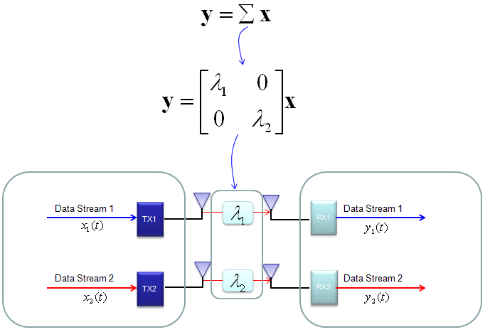
In case of 2 x 2, overall data transmission process can be illustrated as follows. The red arrow and four blocks (h11,h12,h21,h22) between the two antenna is to illustrate the possible data path between the two Tx and two Rx antenna.
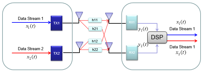
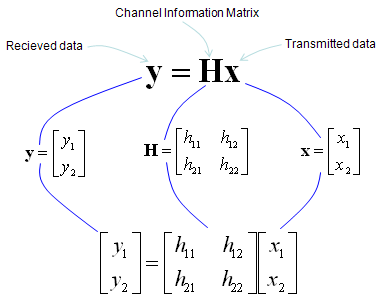
h11, h12,h21,h22 are special numbers (coefficient) to show how much of the data is going through each of the possible path. The greater the value is, the larger portions of data is being transmitted in that path. A matrix which is made up of these channel path coefficient is called "Channel Information Matrix". The reciever and transmitter relationship is represented as follows.
As I said the math itself is very simple. It would be like a first example at the first chapter of any linear algebra book. The important this is how to interpret this equation into real implementation. If I interpret it in an illustration, it would be as the path represented in green arrows. By this way, we can mathematically represent the recieved data (data distorted by the air path between transmitter and reciever antenna), but just calculating the recieved is not our goal (not the function of the reciever). Our goal is to extract/figure out the 'transmitted data (original data)'. Mathematically this is also simple and it is represented in green arrows.
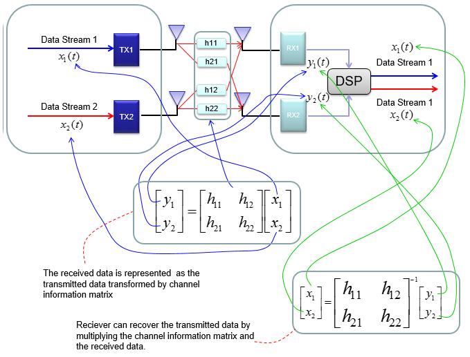
As you see in the process illustrated in green arrow, to recover the transmitted data (original data) from the received data we need to take inverse of the channel information matrix. Unfortunately there are a couple of issues with this method.
i) Not all matrix is invertable. There are some matrix for which inverse matrix does not exists. (Please refer to Matrix section and see what kind of matrix is the one which is not invertable).
ii) Calculating the inverse matrix is not the simple process.
To workaround these problems, we change the channel information matrix into three matrices by the method called SVD(Singular Value Decomposition). See the SVD section in Marix page and clearly understand the meaning of this process. Probably my page would not be enough to give you full understanding about SVD. Google as much materials about this as possible and try to have some "Intuitive" understanding of the concept.
When we apply any mathematical technique in engineering area, it should be meaningful in the engineering sense and should be implementable. The meaning and implementation of SVD can be illustrated as follows.
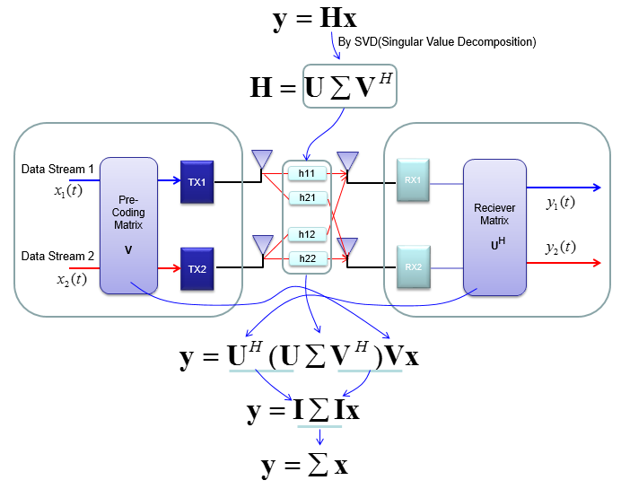
The important point is that by implementing this method, we can express the channel information matrix as a simple 'diagonal matrix'. That diagonal matrix is expressed as follows and can be illustrated as follows. Isn't it look simple and clear ? -:)
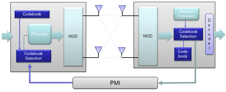
For some MIMO implementation (e.g, TM4 in LTE = Closed Loop MIMO), you estimate the channel and select a specific precoding matrix and send it back to the receiver as shown below.
The algorithm by which UE select the codebook which is best fit for the channel at specific moment is as follows.
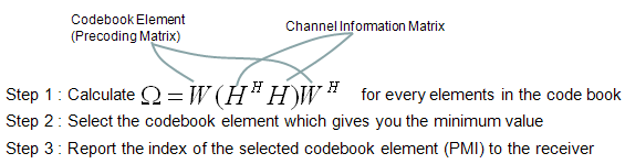
Once a specific codebook element (precoding matrix) is selected as shown here, that precoding matrix is used to transform the incoming bits as explained in Precoding section.
< Considerations for Reality >
Now you know about various aspect of MIMO channel model and conceptual mathematical representation. I hope it make sense to you at least in terms of mathematically. But as you know, when you try to implement the mathematical model into a real system, almost always you would meet something you haven't imagined when you are playing only in mathematical world.
Let's look into folloing mathematical model again.
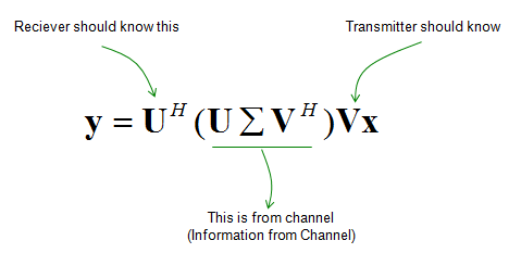
Can you guess what is known variable and what is unknown variable for each side (reciever and transmitter side) ? We can think of followings as a kind of known variables.
- The three matrix at the center can be a known at least to the reciever since the reciever can estimate channel Matrix H from the received signa and calculate these matrix from H.
- The vector x is known to transmitter since it is just the data that's transmitted.
- The matrix U can be a known to the reciever since it can be derived from H.
The issue is how to figure out the matrix V. About this matrix, there are two main problems.
- This is the one that should be used by transmitter, but transmitter does not have any information about H. So it cannot be directly calculatable on transmitter side.
- This matrix is used in transmitter side BEFORE the data (the vector x) is transmitted. How can transmitter know something before it happens ?
One of the most common solution for this is that the reciever analyze channel matrix (H) and inform the transmitter of the best matrix V. This is called 'Closed loop MIMO' and LTE TM4 (Transmission Mode 4) belongs to this category.
Now this kind of closed-loop method can solve all the problems listed above ? Unfortunately No.
What are the problems now ?
The problems that you can easily think of would be as follows :
- Even though UE can figure out the matrix V, it is from the data it just recieved. If it send this information to transmitter, the transmitter will use the information for NEXT transmission. If there is not much difference in channel condition between the current transmission and next transmission, this information from reciever can help a lot for next transmission on transmitter. But if the channel condition changes so fast, the information may not be useful.
- Even though UE figured out correct matrix V, it is huge amount of data and overhead to send the whole matrix itself to the transmitter. In some case like LTE, they use a kind of a workaround. In the workaround, we use only a few/several pre-defined matrices for V and the receiver evaluate each of the candidates and pick the best one and inform the transmitter of the index of the candidate matrix in stead of the whole matrix contents. For example, in LTE TM4 they defined only 4 candidate V matrix (precoding matrix) for 2 x 2 MIMO and 16 candidates for 4 x 4 MIMO. The selected candidate may not be the best fit in terms of mathematics, but it can be a best-effort in terms of trade-off between mathematical accuracy and report overhead.
- In LTE TM 8,9,10 they introduced a method by which the transmiter can use any precoding matrix (V). In this case, the transmitter is using special reference signal called UE-specific (reciever specific) reference signal to help better decoding on the reciever side.
Reference