|
Electronics |
||
|
DC-DC Converter
In most systems including the mobile device, we have only one power source with fixed voltage level (e.g, Battery), but within the device there are many different parts which requires different levels of voltage input. Some part would need the voltage which is lower than the battery, some parts would require lower voltage. How can we supply all those different voltage levels from a single-fixed voltage ? We would need a special components which can translate a voltage from one level to another level. DC-DC converter is a kind of device (circuit) that does this kind of voltage translation.
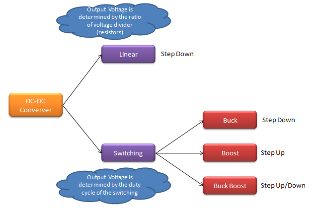
There are several different types of DC-DC voltage converter as shown below. Basically there can be only two different types. One that push up the voltage and the other one which can step down the voltage.
The simplest implementation is just using the two registers in series and you can understand overal mechanism just from high school physics. Those two register will devide the input voltage into two different values. (Of course, the real implementation with decent quality is not as simple as like this.. but the basic concept is the same).
Another type of implementation is that to use 'switching' device which turn on and off the voltage source with certain pattern so that you can get the desired output voltage by taking the average over time. To understand this type of implementation, you have to understand i) what happen during the 'ON' period ii) what happen during the 'OFF' period iii) what kind of output you would get if you take average of the output over time including ON-OFF period.
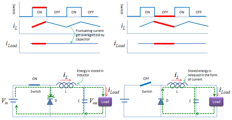
Buck Converter
Buck Converter is a type of Step-Down converter. It means that you can always get the output voltage which is lower than the input voltage. It is also a kind of 'Switching' converter, meaning that an active device functioning as a electric switch is critical part. The simplest form of circuit is as shown below. Of course, the thick line labeled as 'Switch' should be replaced by a switch component (e.g, a transister) in real implementation. The electric current flow during ON or OFF period is expressed in the green dot lines on the circuit. i) Do you understand exactly how (in which path) the current flows during ON or OFF period ? ii) Switch On and Off is always instantaneous and the overal shap is rectangular. But the current change flowing through the inductor is not instantaneous. It is gradually increase and decrease. Do you understand why ? iii) Even though you see fluctuations (gradual increase and gradual decrease) over inductor, you see relatively constant current at the Load. Do you understand why ?
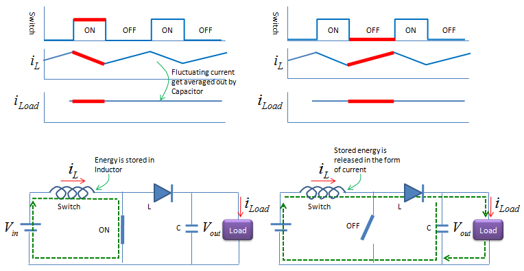
Boost Converter
Boost Converter is a type of Step-Up converter. It means that you can always get the output voltage which is higher than the input voltage. It is also a kind of 'Switching' converter, meaning that an active device functioning as a electric switch is critical part. The simplest form of circuit is as shown below. Of course, the thick line labeled as 'Switch' should be replaced by a switch component (e.g, a transister) in real implementation. The electric current flow during ON or OFF period is expressed in the green dot lines on the circuit. i) Do you understand exactly how (in which path) the current flows during ON or OFF period ? ii) Switch On and Off is always instantaneous and the overal shap is rectangular. But the current change flowing through the inductor is not instantaneous. It is gradually increase and decrease. Do you understand why ? iii) Even though you see fluctuations (gradual increase and gradual decrease) over inductor, you see relatively constant current at the Load. Do you understand why ? iv) Most important question : How can this circuit produce the voltage HIGHER than the input voltage ?
|
||