First I think I should say sorry if you clicked this link in the hope to clear off all the clouds over your head after struggling for so long time trying to understand the details of FEM -:). This is not at all for that level. I just want to give you an idea of application of the mathematical tool called "Matrix" and how a matrix equation is generated from a simple FEM problem.It is true that one of the core part of FEM is converting the problem into a matrix equation, but in reality nobody is doing this by hand because it is too complex to do it manually. There are a lot of software package doing this kind of jobs for various problem spaces. However, understanding this process would be very useful both for understanding the problem space and understanding the logics being used by those software.
- What is the spring problem ?
- How does Hooke's law give the node equations ?
- How do the three equations become a matrix equation ?
- How does FEM software build the same matrix ?
- How much does each spring stretch ?
What is the spring problem ?
Let's fix the model before writing any equation. Every symbol in the matrix at the end of this page comes from the drawing in this section. So it helps to know exactly what each arrow and each label means.
Let's take a very simple cases as follows. You already have seen this problem on many text book or internet pages. Two springs are connected as follows. Let's assume that Node 1 is fixed to a point (like fixed to a wall) and you are pulling away the Node 3. The question how much each of the spring will be elongated ?
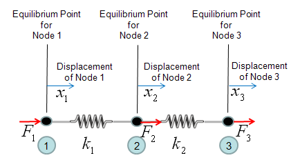
The drawing above shows three nodes on one horizontal line, joined by two springs. Spring k1 joins node 1 and node 2, and spring k2 joins node 2 and node 3.
- The thin vertical lines mark the equilibrium point of each node, where the springs carry no force.
- x1, x2 and x3 are the displacements of the nodes from those points. A positive value means a move to the right.
- F1, F2 and F3 are the forces applied to the nodes from outside, also positive to the right.
- Node 2 is the only node with a spring on each side. That is why it needs the special treatment described next.
One thing you have to think before you start creating the mathmatical model. It is about node 2. If you see the picture above, node 2 is connected to both spring 1 and spring 2. So it would be experiencing forces from two springs and the force labed as F2 is the total force of the two componend forces. So let's define F2 as follows.
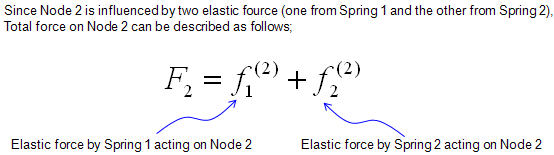
One point about the two small f terms is easy to miss. Spring 1 pulls node 2 back when it is stretched, so the force of the spring itself on node 2 is -k1(x2 - x1). The term f1(2) in the equations is the opposite of that pull. It is the part of the outside force F2 that holds spring 1 in its stretched state. With this reading, F2 = f1(2) + f2(2) is simply the force balance at node 2.
Every node gets one unknown and one force : three nodes give three displacements and three forces, so the final matrix is 3 x 3.A node between two springs collects two forces : F2 is the sum of the parts balanced by spring 1 and spring 2.F is the outside force, not the spring force : the spring pulls on a node with the opposite sign.
How does Hooke's law give the node equations ?
Each spring connects two nodes, so each spring produces one equation at each of its ends. Two springs therefore give four equations. Let's write them and then merge the two equations that belong to node 2.
Now by applying the famous Hooke's law (F = kx), you can draw out four equations as follows.
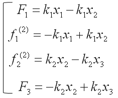
Look at the equations above in pairs. The first two come from spring 1, and they are equal and opposite: F1 = k1(x1 - x2) and f1(2) = -k1(x1 - x2). The last two come from spring 2 in the same way. Only the stretch of a spring matters, which is the difference of its two end displacements. So moving both ends by the same amount produces no force.
Since the two equation (the second and third one is the force being applied to a single node (Node 2). We can combine the two equeation and as result we would finaly have three equations as follows.
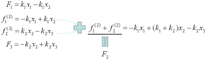
The combined equation for node 2 has k1 + k2 in front of x2, because both springs resist a move of node 2. The neighbours x1 and x3 each appear with the stiffness of the one spring that links them to node 2, with a minus sign.
One spring gives an equal and opposite pair of equations : the force at one end is the negative of the force at the other end.Equations at the same node are added : this is how node 2 gets k1 + k2.Only differences of displacement create force : a spring that moves as a whole stays unloaded.
How do the three equations become a matrix equation ?
Three linear equations in three unknowns are exactly what a matrix equation holds. The coefficients of x1, x2 and x3 in each equation become one row of the matrix, and this matrix is called the stiffness matrix K.
Now we have a set of simultaneous equation comprised of 3 equations. As you already seen above, a simultaneous equation can easily be converted into a matrix equation as follows.
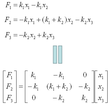
The stiffness matrix above has three properties that every stiffness matrix of this kind shares. First, it is symmetric: element (1, 2) and element (2, 1) are both -k1. Second, the diagonal elements are positive and the off-diagonal elements are negative or zero. Third, every row adds up to zero. For example, the first row gives k1 - k1 + 0 = 0.
The third property has a physical meaning. Multiply K by (1, 1, 1), which moves all three nodes by the same distance. The result is (0, 0, 0), because moving the whole chain stretches no spring. So K has a zero eigenvalue, and its determinant is 0. You cannot solve this matrix equation for x1, x2 and x3 until you fix at least one node. The last section of this page does exactly that.
We saw a very simple example of drawing out a matrix equation from a small set of FEM situation, but in real situation.. most of this process is being automatically done by a software. The procedure that the software use to create the final matrix would be a little different from what I described here.. but the resulting matrix equation should be same.
The stiffness matrix is symmetric : a spring between nodes i and j couples them equally in both directions.Each row sums to zero : a free chain of springs can move as a whole without any force.A free structure has a singular K : its determinant is 0, so a boundary condition is needed before solving.
How does FEM software build the same matrix ?
The paragraph above says that software builds the matrix in a different way. Let's see that way, because it scales to thousands of springs. The idea is to write one small matrix per spring and then add all these small matrices into the big one.
A single spring with stiffness k between node i and node j has its own 2 x 2 element stiffness matrix. It relates the two end forces to the two end displacements.
[ fi ] = [ k   -k ] [ xi ]
[ fj ]   [ -k  k  ] [ xj ]
This is the same equal and opposite pair of equations as before, written as a matrix. The software then places each element matrix into the rows and columns of its own two nodes in the global 3 x 3 matrix. Spring 1 uses rows and columns 1 and 2. Spring 2 uses rows and columns 2 and 3. Where the two overlap, at element (2, 2), their values add up.
[ k1   -k1  0 ]   [ 0  0    0   ]   [ k1   -k1    0   ]
[ -k1  k1   0 ] + [ 0  k2   -k2 ] = [ -k1  k1+k2  -k2 ]
[ 0    0    0 ]   [ 0  -k2  k2  ]   [ 0    -k2    k2  ]
The sum is exactly the matrix found by hand in the previous section. The software never writes a force balance for node 2. The value k1 + k2 appears because two element matrices share that position. This procedure is called assembly, and it works the same way for any number of springs and any connection pattern.
Every element has the same small matrix : for a spring, it is k times [1 -1; -1 1].Assembly adds element matrices at the rows and columns of their nodes : an overlap means that two elements share a node.Hand derivation and assembly give the same K : assembly only replaces the force balance by bookkeeping.
How much does each spring stretch ?
The page started with a question: node 1 is fixed to a wall, node 3 is pulled, and how much does each spring stretch? The previous sections showed that K alone is singular. So the answer needs the boundary condition at node 1.
Node 1 is fixed, so x1 = 0. The first column of K then multiplies zero and drops out. The first row now gives only the reaction force F1 of the wall. So we set it aside and solve the remaining 2 x 2 system. Nobody pushes node 2 directly, so F2 = 0, and the pull at node 3 is F3 = F.
[ k1+k2  -k2 ]   [ x2 ] = [ 0 ]
[ -k2    k2  ]   [ x3 ]   [ F ]
Adding the two rows gives k1x2 = F, so x2 = F/k1. The second row then gives x3 = x2 + F/k2. So spring 1 stretches by x2 - x1 = F/k1, and spring 2 stretches by x3 - x2 = F/k2. Both springs carry the same force F, as they should for two springs in series.
Let's put in numbers. Take k1 = 100 N/m, k2 = 200 N/m and F = 10 N. Then x2 = 0.1 m and x3 = 0.15 m. So spring 1 stretches by 0.1 m and spring 2 by 0.05 m. The first row of K gives the wall reaction: F1 = k1x1 - k1x2 = -10 N. The wall pulls to the left with the same 10 N, so the chain is in balance.
A boundary condition removes a row and a column : a fixed node has a known displacement, and its row gives the reaction force instead.The reduced matrix is not singular : here its determinant is k1k2, which is positive.Each spring stretches by its force divided by its stiffness : in series, both springs carry the full pull F.