CDD is a kind of transmit diversity mechanism implemented by applying a different phase delay (cyclic phase delay) for each OFDM subcarrier. It is used in spatial multiplexing to increase diversity between the 2 spatial paths.
- What does cyclic delay diversity actually do?
- Which transmission modes use CDD?
- What is the difference between NO CDD and LARGE CDD?
- What do the D(i) and U matrices do to the symbols?
- Reference
What does cyclic delay diversity actually do?
The name says delay, and the transmitter does apply one. The receiver sees a phase ramp instead. Those are the same operation seen from the two ends of an FFT. The rest of this page depends on that equivalence, so let's take the time domain first.
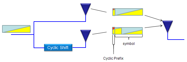
Very simply put, in CDD... one antenna is transmitting the original copy of data and the other antenna is transmitting the cyclic shifted version of the original data as illustrated below (see how the yellow part to represent the cyclic shift)
The shift costs no extra bandwidth and no extra power. It only decides which copy of the symbol each antenna sends, so the two paths stop fading together.
One source, two branches : a single block of data splits on the left and feeds both antennas. Neither branch loses anything, and neither carries a second stream.Only the lower branch is shifted : the box labelled Cyclic Shift sits on that path alone, so the upper antenna transmits the original block.The yellow tail wraps round to the front : in the upper symbol the yellow section sits at the end, and in the lower one it has moved to the start. That wrap is what makes the shift cyclic rather than a plain delay.The symbol keeps its length : nothing is pushed past the end of the block, so the receiver's FFT window still covers one whole symbol.The cyclic prefix goes on afterwards : the picture marks the small block at the front of the shifted symbol as the Cyclic Prefix, with the symbol proper bracketed to its right.
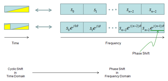
If you represent the transmitted data in frequecy domain, the original data and the cyclic shifted version can be represented as follows. As you see, the cyclic shif in time domain produce the phase shift for each symbols in frequency domain and it generate the same effect as frequency diversity.
The same operation, written in the domain the transmitter actually works in. A cyclic shift of the samples is a multiplication of the subcarriers, and the multiplier turns a little further on every subcarrier.
Time on the left, frequency on the right : the two small blocks are the original symbol and the shifted one. The rows of cells beside them are the subcarriers those symbols are built from.The upper row is untouched : s0, s1 and the rest arrive from the layer mapper and go out as they are.The lower row carries a phase ramp : subcarrier k becomes skejkθ, so the angle grows by θ from one subcarrier to the next. The two right hand cells are both labelled sn-2 in the picture, but the exponents (n−2)θ and (n−1)θ show that the second of them is subcarrier n−1.Only the angle moves : ejkθ has magnitude one, so no subcarrier gains or loses power. This is why CDD costs no power.The caption under the picture states the equivalence : cyclic shift in the time domain, phase shift in the frequency domain. One arrow connects the two.
A cyclic shift is not a delay : the tail wraps to the front instead of running past the end, so the symbol boundary and the cyclic prefix still work.The transmitter never leaves the frequency domain : the shift is applied as one multiplication per subcarrier, which is why the author's later sections find it inside the precoder.The diversity gained is frequency diversity : the two antennas add constructively on some subcarriers and destructively on others. A flat fade becomes a frequency selective one, and the channel coder can work through that.
Which transmission modes use CDD?
CDD is not something the UE switches on by itself. It arrives with the transmission mode, and only one LTE transmission mode ever asks for it. The table below is the author's summary. After it I have added what 36.213 says about when TM3 really uses CDD, because the answer is narrower than one row can show.
CDD is applied differently for each transmission mode as shown in the following table.
|
TM type |
Number of Antenna |
CDD Type |
|
TM1 |
1 |
NO CDD |
|
TM2 |
2 |
NO CDD |
|
TM3 |
2 |
LARGE CDD |
|
TM4 |
2 |
NO CDD |
|
TM5 |
2 |
NO CDD |
|
TM6 |
2 |
NO CDD |
|
TM7 |
1 |
NO CDD |
TM3 is open loop spatial multiplexing, and the words open loop are why CDD is there. In a closed loop mode the UE reports a precoding matrix indicator, so the eNB knows which precoder the channel currently favours. TM3 asks for no such report. The UE sends a rank indicator and a CQI, and nothing that names a precoder.
So the eNB has to choose one without help. 36.211 clause 6.3.4.2.2 settles that in two different ways, depending on how many antenna ports there are. On two ports the precoder is fixed at codebook index 0 and never moves. On four ports the eNB cycles through precoder indices 12, 13, 14 and 15, and the UE is allowed to assume that pattern.
Neither choice changes fast enough on its own to stop a deep fade covering the whole band. That is the job D(i) does. It changes with every subcarrier index, so the effective channel differs from one subcarrier to the next even while W(i) does not change.
The rank 1 fallback comes out of the same table. Table 6.3.4.2.2-1 starts at two layers and carries no row for one, so large delay CDD is not defined for a single layer transmission. With one layer there is nothing for U to mix, and no second port for D(i) to rotate against. 36.213 therefore assigns a rank 1 grant in TM3 to transmit diversity instead, which is the scheme TM2 uses all the time.
TM3 is the only mode that uses it : 36.213 Table 7.1-5 gives large delay CDD to Mode 3 alone. Every other mode in that table is single antenna port, transmit diversity, closed loop spatial multiplexing or MU-MIMO.TM3 uses it only above rank 1 : 36.213 Table 7.2.3-0 lists Mode 3 as transmit diversity when the rank indicator is 1, and large delay CDD otherwise. A rank 1 grant in TM3 is therefore not CDD at all.The DCI format decides as well : in Table 7.1-5 a Mode 3 grant on DCI format 1A is transmit diversity. Only DCI format 2A can be large delay CDD.The table stops at TM7 because TM8 to TM10 came later : none of the three uses large delay CDD. They transmit on ports 7 to 14 with UE specific reference signals, so their diversity comes from beamforming instead.36.213 hands the definition to 36.211 : clause 7.1.3 says the UE may assume the transmission follows large delay CDD as defined in 36.211 clause 6.3.4.2.2. That clause is what the rest of this page works through.
What is the difference between NO CDD and LARGE CDD?
The question in this heading is the author's own, and so is the honest answer below it. Let me add the structural part. Both schemes run through the same precoding block, and the difference is two extra matrices that only the CDD path inserts. The pictures in this section show where those matrices sit.
What is the difference between NO CDD (without CDD) and LARGE CDD ? To be honest, I don't think I can explain it in easy way implying that even I don't have fully-detailed understanding on this. If I don't explain anything in plain term. You can refer to 36.211 section 6.3.4.2 Precoding for spatial multiplexing or you can refer to the precoding section of LTE Basic Procedure page. (Sometimes there is some concept that you cannot understand without going through the mathmatical description and pulling your hair for long time).
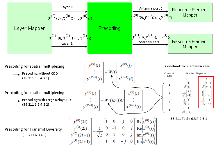
If you look at the following illustration, CDD is implemented by applying two additional matrix (D, U) to channel matrix (W) in precoding process. CDD being appiled in Precoding Step implies that real implementation of CDD is done in frequency domain and will be converted to Time Domain right before being transmitted through Antenna.
Three precoding schemes drawn against one block diagram. Only the middle one carries D(i) and U, and those two matrices are the whole of what large delay CDD adds.
The block diagram on top is common to all three : the layer mapper delivers x(0) and x(1), and the precoder turns them into y(0) and y(1). Each output then goes to its own resource element mapper and antenna port.Without CDD the equation is y = W(i)x : 36.211 clause 6.3.4.2.1, one matrix, taken from the codebook.With large delay CDD it is y = W(i)D(i)Ux : 36.211 clause 6.3.4.2.2. The same W(i) is still there, with D(i) and U inserted between it and the data.Transmit diversity is a different equation altogether : 36.211 clause 6.3.4.3 maps the real and imaginary parts of two symbols onto four outputs across two symbol periods. It sits in the picture to show what CDD is not.The codebook on the right is 36.211 Table 6.3.4.2.3-1 : the red box marks the two layer column, and index 0 of that column is the identity matrix scaled by 1/√2.On two antenna ports the spec fixes that choice : 36.211 clause 6.3.4.2.2 says the precoder is the matrix for precoder index 0 of Table 6.3.4.2.3-1. So W(i) does not vary with i and there is no PMI to report, which is why the author can drop it from the algebra further on.
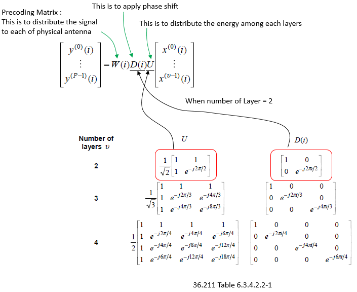
If you look into the CDD part of precoding, the matrix are as follows. If you see the D(i) matrix, it has all zero value except diagonal line. The values on diagonal line performs phase shift.
Only one of the three matrices depends on the subcarrier index. That single dependence is what spreads a layer across frequency, and the table sets its step size from the rank.
Three matrices, three jobs : the green notes label W as distributing the signal to each physical antenna. They label D as applying the phase shift, and U as distributing the energy among the layers.D(i) is diagonal and U is not : every entry of D(i) off the diagonal is zero, so D(i) rotates each layer on its own. U is full, so it mixes them.The size follows the layer count : two layers give 2x2 matrices, three give 3x3, four give 4x4. The red boxes mark the two layer row, which is the one the rest of this page uses.The phase step comes from the number of layers : D(i) at two layers carries e-j2πi/2, at three layers e-j2πi/3 and e-j4πi/3, and at four layers the steps are quarter turns. More layers means a finer ramp.U carries a 1/√υ in front : 1/√2, 1/√3 and 1/2 down the three rows. That keeps the transmitted power the same whatever the rank.
Large delay CDD is ordinary precoding plus two matrices : nothing else in the transmit chain changes, and the codebook is the same codebook.D(i) depends on the subcarrier index and U does not : that is where the per subcarrier behaviour of the first section enters the algebra.On two antenna ports W(i) is pinned : the spec fixes it to codebook index 0, so D(i) is the only thing that varies across subcarriers.
What do the D(i) and U matrices do to the symbols?
Two matrices multiplied out is a small piece of arithmetic. It answers a question the block diagrams cannot. For one subcarrier, what exactly leaves port 0, and what leaves port 1? The pictures below work that out for a two layer transmission, one subcarrier index at a time.
I know not so many people want to do math, but sometimes it would be easier to clarify many things if you do some math.
If you plug 2x2 CDD matrix into Precoding equation, you would get a format as shown below. (I just obmitted W(i) part for simplicity. It is just doing scaling without any phase shift or rotation). Just try to understand overall function of Matrix D(i) and U as commented below and be aware that D(2,2) of D(i) matrix gets toggled between +1 and -1 depending on whether 'i' is odd or even.
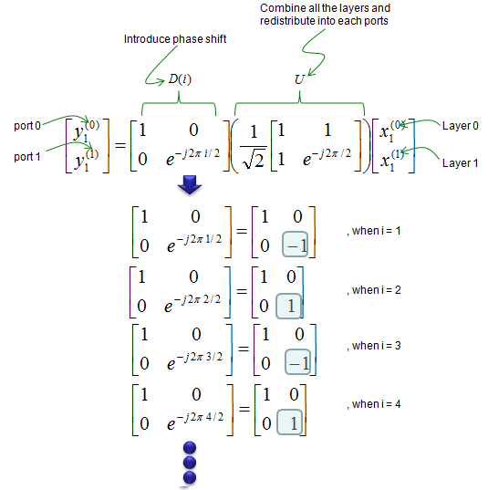
Only one entry of D(i) changes. Its lower right entry alternates between −1 and +1 as the subcarrier index counts up, and every other term in the product stays where it is.
The two brackets are labelled : introduce phase shift sits over D(i), and combine all the layers and redistribute into each ports sits over U.Layers go in on the right, ports come out on the left : the blue labels mark x(0) and x(1) as Layer 0 and Layer 1. They mark y(0) and y(1) as port 0 and port 1.The top left entry of D(i) is always 1 : port 0 therefore takes no phase shift from D(i), whatever the subcarrier.U carries no i at all : its exponent is e-j2π/2 with no index in it, so U is the same matrix on every subcarrier.The four rows evaluate the one exponent that moves : i = 1 gives −1, i = 2 gives +1, i = 3 gives −1, i = 4 gives +1. The boxed entries are the ones that change.So D(i) follows the parity of i : odd subcarriers get −1 and even ones get +1. Every second subcarrier is treated the same way.
If you want to clarify even further, expand the matrix equation and analyze the resulting equation as shown below.
If you multiply symbols from Layer Mapper with CDD matrix, you would easily notice how each of the symbols get combined and allocated to each of the antenna. Notice that the result gets different depending on whether the index of symbols are odd or even.
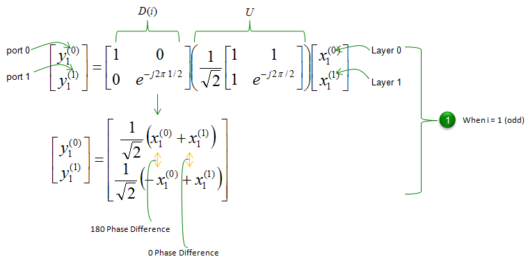
One odd subcarrier, fully expanded. Port 0 takes the sum of the two layers and port 1 takes their difference, with the minus sign landing on layer 0.
This is the case i = 1 : the green marker on the right labels it when i = 1 (odd), so D(i) has −1 in its lower right corner.Port 0 sends the sum : y(0) is (1/√2)(x(0) + x(1)).Port 1 sends the difference : y(1) is (1/√2)(−x(0) + x(1)).Layer 0 arrives at the two ports 180 degrees apart : the left yellow arrow marks that, comparing +x(0) above with −x(0) below.Layer 1 arrives in phase : the right yellow arrow marks 0 degrees, comparing +x(1) with +x(1).Both ports carry both layers : neither port is dedicated to one layer, and that mixing is the work U does.
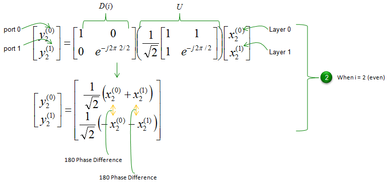
The same expansion for an even subcarrier, where D(i) becomes the identity matrix. The minus sign should move from layer 0 to layer 1, and the drawing keeps it on both.
This is the case i = 2 : the exponent e-j2π2/2 is e-j2π, which equals 1, so D(i) here is the identity matrix and the product reduces to U on its own.The lower row carries a sign error : with D(i) equal to the identity, port 1 should send (1/√2)(x(0) − x(1)). The drawing shows (1/√2)(−x(0) − x(1)) instead, which is why both of its arrows read 180 degrees.The page's own text has it right : the paragraph introducing the two layer expansion says that D(2,2) toggles between +1 and −1 with the parity of i. The list that closes this section says the same. Its fact iii) needs 180 degrees on port 1 for both layers. Only (x(0) − x(1)) gives that.Read the even case as the mirror of the odd one : 0 degrees on layer 0 and 180 degrees on layer 1. That swap from one subcarrier to the next is what the scheme depends on.
Following is some facts you can directly read out from the equations listed above.
Each antenna port (port 0 and port 1) transmit the portions from the both layers. (Symbols from the two layers are linearly combined and redistributed between two antenna port)
i) The phase difference of layer 1 data between Antenna 0 and Antenna 1 is 180 or 0 depending on i.
ii) The phase difference of layer 0 data between Antenna 0 and Antenna 1 is 0 or 180 depending on i.
iii) The phase difference of layer 0 and 1 data between odd numbered symbol and even numbered symbol is 180 on Antenna port 1.
iv) The phase difference of layer 0 and 1 data between odd numbered symbol and even numbered symbol is 0 on Antenna port 0.
The above facts of i) and ii) tell us that the same signal ( layer 0 or 1 data ) is transmitted from the two Tx-antenna ports with the phase relation changed every subcarrier by 180-degree step.
Both ports always carry both layers : U mixes them, so no layer maps onto one antenna port.Only the signs change across subcarriers : every magnitude stays at 1/√2, so CDD never moves power from one subcarrier to another.Port 0 never changes : y(0) is (1/√2)(x(0) + x(1)) for every i, because the top left entry of D(i) is fixed at 1.Port 1 flips every subcarrier : layer 0 runs 180, 0, 180, 0 degrees against port 0 as i counts up, and layer 1 runs 0, 180, 0, 180.That flip is the diversity : the two paths combine differently on every subcarrier, so a deep fade on one of them does not repeat on the next.
Reference
- 36.211 : 3GPP - E-UTRA; Physical channels and modulation, v19.3.0. Clause 6.3.4.2.1 (precoding without CDD), clause 6.3.4.2.2 (precoding for large delay CDD) and Table 6.3.4.2.2-1.
- 36.213 : 3GPP - E-UTRA; Physical layer procedures, v19.4.0. Table 7.1-5 (transmission mode to PDSCH scheme), Table 7.2.3-0 (scheme assumed for CSI reporting) and clause 7.1.3 (large delay CDD scheme).