CFI is a indicator telling how many OFDM symbols are used for carrying control channel (e.g, PDCCH and PHICH) at each subframe. If CFI is set to be 1 for a subframe, it means one symbol (the first symbol) at the subframe is used for PDCCH allocation. If CFI is 2, it means two symbols (the first and the second symbol) are used for PDCCH. If CFI is 3, you know the answer -:)
- What does CFI change in the subframe ?
- What would be the best CFI value ?
- Why not set CFI = 1 everywhere ?
- Reference
What does CFI change in the subframe ?
CFI moves one boundary, and everything else on this page follows from where that boundary sits. It is the line between the control region and PDSCH, and it moves in whole OFDM symbols. The two pictures below show the line first, then the bit pattern that carries its position across the air.
(I created following subframe structure using LTE Resource Grid and edited to fit the topics of this page)
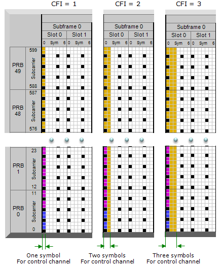
The control region grows downward from symbol 0, and every symbol it takes is a symbol PDSCH does not get. Nothing else in the subframe moves, which is why CFI is one number rather than an allocation.
Three panels, one subframe each : the labels read CFI = 1, CFI = 2 and CFI = 3. All three show Subframe 0, split into Slot 0 and Slot 1, with the symbols numbered 0 to 6 inside each slot.The grid is drawn with its middle cut out : the top block is PRB 49 and PRB 48, subcarriers 599 down to 576. The bottom block is PRB 1 and PRB 0, subcarriers 23 down to 0. Fifty PRBs makes this a 10 MHz carrier, by 36.101 Table 5.6-1.The coloured band at the left edge is the control region : one symbol wide in the first panel, two in the second, three in the third. The green arrows underneath read One symbol, Two symbols and Three symbols For control channel.The band is not one colour, and that matters later : it is yellow at the top of the grid. In PRB 1 and PRB 0 it turns magenta, with blue at the very bottom. Several control channels share those symbols, and PDCCH only gets what the others leave.The black cells sit inside the control region too : they recur every six subcarriers, in the first symbol as well as later ones. Reference signal REs are not available to PDCCH either, so a control symbol is never wholly PDCCH.Everything to the right of the band is unchanged : CFI does not reshape the subframe. It only says where the reader should stop treating symbols as control.
This CFI is carried by a specific physical channel called PCFICH. PCFICH is carrying only CFI without any other information. You may ask "why do we need a special physical channel carrying only one number ?". It is because CFI is made up of 32 bits data even though the types of the bit pattern is only 4. The bit pattern and the CFI value mapping is as follows (3GPP 36.212 5.3.4 Control format indicator).
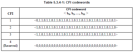
Two bits of information, sent as thirty-two. The redundancy is the answer to the question in the paragraph above: a UE that cannot read this number cannot read anything else in the subframe, so the coding is deliberately heavy.
The header gives the length : the column is titled CFI code word < b0, b1, …, b31 >. Counting b0 to b31 inclusive gives thirty-two bits.Four rows, three of them usable : CFI 1, 2 and 3, then CFI 4 marked (Reserved). Two bits would carry all four.The three live codewords are one pattern at three phases : each is the repeating triple 0,1,1 started at a different offset and cut off at thirty-two bits. The reserved row is all zeros.No two codewords are close : the four rows are far apart, and the smallest Hamming distance between any pair is 21 bits. A receiver can lose a third of the codeword and still pick the right row.This is why PCFICH exists as its own channel : thirty-two coded bits cannot be carried inside PDCCH, because the UE has to decode them before it knows how large PDCCH is.
CFI is a boundary, not a resource allocation : it names a symbol count, and the rest of the subframe layout is fixed by other rules.The value and the symbol count are not always the same number : the next section is entirely about the one bandwidth where they differ.A control symbol is never all PDCCH : reference signals, PCFICH and PHICH take their share of the same symbols first.The codeword is 32 bits for 2 bits of payload : 36.212 Table 5.3.4-1 spends that on distance, because nothing else in the subframe can be decoded until CFI is.
What would be the best CFI value ?
Two specifications answer this, and they answer different questions. 36.212 says which values are legal and what each one means in symbols. 36.508 picks one value per bandwidth for conformance testing. Neither is a throughput recommendation, which is where the rest of this section goes.
Would there be any value that is the best for every subframe ? or for every situation ?
The answer would be No best value for every subframe and every situation.. but there can be some recommended value for a specific situation.
First, let's think about the general guide from 3GPP specification. We have a couple of different places of 3GPP specification mentioning about CFI.
First place is 3GPP 36.212 5.3.4 Control format indicator.. you can see following statement.
The CFI takes values CFI = 1, 2 or 3.
For system bandwidths with "Max Number of RBs for the System Bandwidth > 10", the span of the DCI in units of OFDM symbols, 1, 2 or 3, is given by the CFI.
For system bandwidths with "Max Number of RBs for the System Bandwidth <= 10", the span of the DCI in units of OFDM symbols, 2, 3 or 4, is given by CFI+1.
=> Basically this says.. you can specify any value of 1,2,3 in any bandwidth, but the conversion from 'CFI value' to 'number of OFDM symbols for the span of DCI' is different as follows.
Case 1 : For system bandwidths with "Max Number of RBs for the System Bandwidth > 10"
the number of OFDM symbols for the span of DCI = CFI Value
Case 2 : For system bandwidths with "Max Number of RBs for the System Bandwidth <= 10"
the number of OFDM symbols for the span of DCI = CFI Value + 1
According this rule, only System BW 1.4 Mhz is supposed to follow Case 2 rule and all other system BW is supposed to follow Case 1.
The description above would tell you the whole possible range of value of CFI, but does not tell you much about which value would be better than others.
You can find another guide lines in 4.3.3.3 Mapping of downlink physical channels and signals to physical resources of 36.508 as follows.
CFI = 3 for 1.4, 3 and 5 MHz system bandwidths
CFI = 2 for 10, 15 and 20 MHz system bandwidth
It seems to narrow down the value a little bit better for a couple of cases. It may be recommended well for most of the situation. However, if you are trying to achieve or test maximum throughput. You may have to think more carefully.
Large CFI value measn less space for PDSCH.. it means .. you would have higher code rate in the subframe with large CFI comparing to the subframe with low CFI value. You would also know that it would get more difficult for UE to decode PDSCH when Code Rate gets higher. According to my experience, the value specified in 36.508 works fine for most of the case including max throughput case in Cat 3 device. But in case of Cat 4 or higher, it would be harder to achieve max throughput with CFI value 2 or 3.. in this case most of UE fails at PDSCH decoding and report HARQ NACK causing PHY layer retransmission. So general tips for max throughput case would be "Use CFI = 1 for Cat 4 or higher max throughput case". If you want to see more quatative example for this description, refer to Is there any theoretical limit for Code Rate ? section of Code Rate page.
Putting the two rules and the test recommendation side by side makes the exception easy to see. Only the first row behaves differently, and it is the only bandwidth whose RB count falls at or below ten.
|
System BW |
NRB |
36.212 rule |
CFI = 1 |
CFI = 2 |
CFI = 3 |
36.508 4.3.3.3 uses |
|
|
6 |
|
2 symbols |
3 symbols |
4 symbols |
CFI = 3, so four symbols of control |
|
|
15 |
CFI |
1 symbol |
2 symbols |
3 symbols |
CFI = 3 |
|
|
25 |
CFI |
1 symbol |
2 symbols |
3 symbols |
CFI = 3 |
|
|
50 |
CFI |
1 symbol |
2 symbols |
3 symbols |
CFI = 2 |
|
|
75 |
CFI |
1 symbol |
2 symbols |
3 symbols |
CFI = 2 |
|
|
100 |
CFI |
1 symbol |
2 symbols |
3 symbols |
CFI = 2 |
NRB comes from 36.101 Table 5.6-1. The 1.4 MHz row is the whole of Case 2, and it is the row where a CFI of 3 costs four symbols rather than three.
The legal range is always 1, 2 or 3 : 36.212 never lets CFI itself take the value 4. The fourth codeword is reserved.Only 1.4 MHz adds one : six RBs is the only transmission bandwidth configuration at or below ten, so every other row reads CFI straight off as a symbol count.1.4 MHz at CFI = 3 spends four of fourteen symbols on control : that is the worst case in the table, and it is why the narrow bandwidths are the awkward ones.36.508 is a test configuration, not advice : it fixes one value per bandwidth so that conformance tests are repeatable. It is still a sensible starting point.The two specifications never contradict each other : every 36.508 value is inside the 36.212 range. 36.508 is choosing, not extending.
Why not set CFI = 1 everywhere ?
The throughput argument all points one way, so the obvious choice is to set CFI to 1 and stop. The reason that fails is a floor rather than a preference. PDCCH has to fit, and what has to fit is countable, so let's count it.
Then you may ask.. why don't we just set CFI = 1 for every case ?
Answer to this question is not as simple as you might have expected. The bottom line is 'you have to secure the minimum number of CCEs for the necessary PDCCH for each subframe'. If you set CFI to 1 in a very narrow bandwidth you may break this rule.
For the number of CCE required for number of PDCCH, refer to 36.213 Table 9.1.1-1. If you want to get more detailed explanation on CCE, PDCCH related issues, refer to following pages.
- Resource Allocation and Management Unit
- PDCCH Candidate and Search Space
- PDCCH Resource Allocation
- CCE Index Calculation/PDCCH Decoding/Blind
To many things to study just to figure out proper CFI number ?
True.. Simple rule of thumb is that you may easily set CFI value to 1 in case of 10 Mhz and higher bandwidth.. but in case of 5 Mhz and lower, you have to be very careful to check if the value meets the minimum number of CCE requirement. Since this requirement is influenced by phich-Resource IE in MIB and aggregation level, you have to consider those factors as well.
The counting runs in one direction, and each step takes something away. 36.508 clause 4.3.3.3 gives the order for the control symbols. PCFICH maps into 4 REGs spread uniformly across the whole system bandwidth in symbol 0. Each PHICH group then maps into 3 REGs, placed on the REGs that PCFICH did not take. What is left goes to PDCCH, in the specification's own words the remaining REGs not allocated to both PCFICH and PHICH.
36.211 clause 6.8.1 turns that remainder into the unit the scheduler actually spends. A control channel element corresponds to 9 resource element groups, and the clause counts the REGs not assigned to PCFICH or PHICH. So the number of CCEs in a subframe is the leftover REG count divided by nine, and CFI is the only term in that chain the network sets directly.
The chain is easier to read as a diagram than as prose, because each row removes something before the next row divides. The diagram below follows one subframe from the control region down to the CCEs that PDCCH can actually use.
Only the top row is a choice. Every row under it is arithmetic, so raising CFI is the only thing that can change when the bottom row does not fit.
The number in the bottom row is worth seeing in its own table, because it is the part the page above sends you to 36.213 for. These are the candidates a UE monitors, and the common rows are the ones no scheduler can skip.
|
Search space type |
Aggregation level |
Size in CCEs |
Number of PDCCH candidates |
|
|
1 |
6 |
6 |
|
|
2 |
12 |
6 |
|
|
4 |
8 |
2 |
|
|
8 |
16 |
2 |
|
|
4 |
|
4 |
|
|
8 |
|
2 |
36.213 Table 9.1.1-1, with the note that the sizes assume one carrier. The two common rows are the floor: SIB, paging and RAR scheduling all live there, so those 16 CCEs have to exist before any UE gets a grant.
CFI is the only free variable in the chain : PCFICH is fixed at 4 REGs, the PHICH size follows phich-Resource in MIB, and 9 REGs per CCE is a constant. Symbols are all the network can add.The common search space is the hard floor : 36.213 Table 9.1.1-1 puts it at 16 CCEs, and it is common because every UE in the cell has to find it.Narrow bandwidth is where CFI = 1 breaks : fewer RBs means fewer REGs per symbol, so the same 16 CCEs need a larger share of the subframe.Reference signals shrink the budget before any of this : the subframe picture further up shows black cells inside the control symbols, and REGs are counted around them.The rule of thumb above matches the arithmetic : at 10 MHz and wider there are enough REGs in one symbol to cover the floor. Below 5 MHz there may not be.
Reference
- 36.212 : 3GPP - E-UTRA; Multiplexing and channel coding, v19.3.0. Clause 5.3.4 (control format indicator) and clause 5.3.4.1 with Table 5.3.4-1 (CFI code words).
- 36.211 : 3GPP - E-UTRA; Physical channels and modulation, v19.3.0. Clause 6.8.1 (CCE to REG mapping) and Table 6.8.1-1 (supported PDCCH formats).
- 36.213 : 3GPP - E-UTRA; Physical layer procedures, v19.4.0. Table 9.1.1-1 (PDCCH candidates monitored by a UE).
- 36.508 : 3GPP - Common test environments for UE conformance testing, v19.2.0. Clause 4.3.3.3 (mapping of downlink physical channels and signals to physical resources).
- 36.101 : 3GPP - E-UTRA; UE radio transmission and reception, v20.0.0. Table 5.6-1 (transmission bandwidth configuration per channel bandwidth).