Every LTE carrier has a centre frequency, but almost nothing in the system ever names that frequency in megahertz. The UE and the network exchange an integer instead, and that integer is the EARFCN. This page holds the table that maps between the two, the formula that does the arithmetic, and the reason the numbering looks the way it does.
I'll start with why an integer is used at all, because the answer explains the shape of everything that follows. Then we'll read the band table and work through the conversion in both directions. The last section covers the one place where the numbering outgrew the field that carries it.
- What is an EARFCN, and why not just use the frequency in MHz?
- What should you notice in 36.521-1 Table 5.4.4-1?
- How do you convert between an EARFCN and a frequency?
- Why do some EARFCNs need more than 16 bits?
What is an EARFCN, and why not just use the frequency in MHz?
A carrier has a frequency, so a number in megahertz looks like all anyone would need. LTE uses an integer instead. The integer is the EARFCN, short for E-UTRA Absolute Radio Frequency Channel Number, and it is worth understanding why before using the conversion formula.
Three things make an integer better than a frequency in this role. The first is that an LTE carrier frequency is never arbitrary. Carriers sit on a 100 kHz raster, so the only legal centre frequencies are multiples of 100 kHz. An integer that counts raster steps can name every legal carrier and nothing else. A decimal number in megahertz can also name 2140.03 MHz, which no LTE carrier ever uses.
The second is size. Signalling carries the channel number many times over, in the measurement configuration, in the neighbour cell lists and in the handover command. An integer field is cheaper to send than a decimal frequency, and it needs no unit beside it.
The third is that the number identifies the band as well as the frequency. Each band owns its own block of channel numbers, so EARFCN 1575 means Band 3 and nothing else. That is what the offset columns of the table below arrange, and it is why the numbering looks strange on a first reading.
One detail is easy to get wrong, so let me state it early. The EARFCN identifies the centre of the carrier, not its lower edge. A 10 MHz carrier on EARFCN 1575 occupies 5 MHz either side of the frequency the formula returns. The channel number says nothing at all about that bandwidth.
An EARFCN counts raster steps, not megahertz : the raster is 100 kHz, which is where the 0.1 in the formula comes from. One step of the channel number is one step of 100 kHz.The number carries its band with it : each band owns a distinct block of integers, so a channel number on its own already tells you which band you are in.Downlink and uplink are numbered separately : an FDD band has two blocks and two offsets. A TDD band has one carrier, so both of its columns hold the same numbers.The number points at the carrier centre : work the edges out from the bandwidth yourself, because the EARFCN does not carry it.
What should you notice in 36.521-1 Table 5.4.4-1?
The table below is the lookup that every conversion depends on. It is worth reading once for its shape before using it for a number. Several of its rows behave differently from the rest, and those differences are easy to miss.
Each row is one operating band. The three downlink columns give the band’s lowest downlink frequency, the offset that starts its downlink numbering, and the range of channel numbers it owns. The three uplink columns do the same for the uplink. 36.521-1 Table 5.4.4-1 is reproduced here as two screenshots, because the full table is too tall for one. The lower picture continues the upper one and carries no header row of its own, so read its columns against the header above it.
< 36.521-1 Table 5.4.4-1: E-UTRA channel numbers >

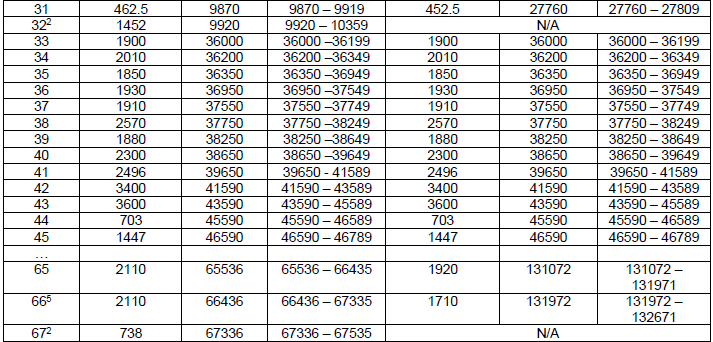
Six columns, split into two halves : FDL_low, NOffs-DL and the range of NDL on the left, then FUL_low, NOffs-UL and the range of NUL on the right. The band number is the first column.An FDD band carries a different block on each side : Band 1 runs 0 to 599 in the downlink and 18000 to 18599 in the uplink. Same width, different block.A TDD band repeats itself : from Band 33 downward the two halves are identical. Band 38 shows 2570 MHz, offset 37750 and range 37750 to 38249 on both sides, because the uplink and the downlink share one carrier.Some bands have no uplink at all : Bands 29, 32 and 67 show N/A across the whole uplink half. They are downlink only, and a UE uses one as a secondary cell rather than on its own.Band 24 reverses the usual order : its FUL_low of 1626.5 MHz sits above its FDL_low of 1525 MHz. Every other FDD row in the table puts the uplink below the downlink.The table skips rows : a row of dots sits between Band 14 and Band 17, and another between Band 45 and Band 65. Those bands exist, but this screenshot does not list them.Band 65 and Band 66 restart the numbering high up : Band 65 begins its downlink block at 65536 and its uplink block at 131072. The last section on this page explains why that particular number.
One check is worth doing once, because it confirms you have read the columns correctly. The width of a band’s block of numbers always matches the width of its spectrum. Band 1 owns 600 downlink channel numbers. 600 steps of 100 kHz is 60 MHz, and Band 1 covers exactly 2110 to 2170 MHz. Band 41 owns 1940 numbers, or 194 MHz, running from 2496 MHz. Every row works out the same way.
Read the band first, then the offset : the offset is what maps a band's block of integers onto its block of spectrum. With the wrong row the formula still returns a number, and that number is in the wrong band.The two halves are independent : never subtract a downlink offset from an uplink channel number. On an FDD band the two blocks are thousands apart, so the mistake is obvious. On a TDD band it is invisible, because the two are equal.This screenshot is a subset : the dotted rows mean bands are missing, and bands have been added since. Go to 36.101 section 5.7.3 for the complete and current list.
How do you convert between an EARFCN and a frequency?
With the right row from the table, the conversion is one line of arithmetic. Take the channel number, subtract the band’s offset, and what remains is how many 100 kHz steps you sit above the bottom of the band. Multiply by 0.1 to turn those steps into megahertz, then add the band’s lowest frequency.
The formula below states that for both directions at once. The downlink line uses the downlink offset with the downlink low frequency, and the uplink line uses the uplink pair. The two lines never share a term, which is the point the previous section made from the table.
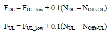
The EARFCN to frequency conversion, from 36.521-1 Table 5.4.4-1. Both directions have the same shape: start at the bottom of the band, then add 100 kHz for every channel number above that band’s offset.
FDL and FUL : the carrier centre frequency in MHz, which is what you are solving for.FDL_low and FUL_low : the lowest frequency of the band, taken from the second and fifth columns of the table above.NDL and NUL : the EARFCN itself, the number a log or an RRC message actually carries.NOffs-DL and NOffs-UL : the first channel number of the band's block, from the third and sixth columns.0.1 : megahertz per step, which is the 100 kHz channel raster written in MHz. This is the only constant in the formula, and it is the same for every band.
The offset is the part that does the real work, and a picture shows why better than the formula does. Figure 1 puts two downlink bands on a frequency axis, and their blocks of channel numbers on a second axis underneath.
Figure 1. The channel numbers are not ordered by frequency. Each band owns its own block of integers, and the offset in 36.521-1 Table 5.4.4-1 is what maps that block onto the band's piece of spectrum. So an EARFCN can only be read once you know which band it belongs to.
The upper axis is spectrum : Band 3 occupies 1805 to 1880 MHz and Band 1 occupies 2110 to 2170 MHz, both read from the table above.The lower axis is the integers : Band 1 holds 0 to 599 and Band 3 holds 1200 to 1949. Neither block overlaps another, which is what makes a bare channel number unambiguous.The dashed connectors cross : Band 1 is the higher band and carries the lower numbers. The channel numbering follows the order the bands were standardised in, not the order they sit in the spectrum.Each block is as wide as its band : Band 3 is the wider of the two bands on the upper axis. Its block is also the wider of the two on the lower axis.
Four worked examples follow, one for each case you are likely to meet. Every number in them comes from the table above, so you can check any row by finding its band there.
Band |
Direction |
EARFCN |
Flow (MHz) |
NOffs |
Result |
1 |
Downlink |
300 |
2110 |
0 |
2110 + 0.1 × (300 − 0) = |
3 |
Uplink |
19500 |
1710 |
19200 |
1710 + 0.1 × (19500 − 19200) = |
7 |
Downlink |
3100 |
2620 |
2750 |
2620 + 0.1 × (3100 − 2750) = |
38 |
Both (TDD) |
38000 |
2570 |
37750 |
2570 + 0.1 × (38000 − 37750) = |
Going the other way is the same line rearranged : N = NOffs + 10 × (F − Flow). A frequency that does not give a whole number is not a legal carrier in that band.Check that the answer lands inside the band : if the frequency falls outside the range the band covers, you used the wrong row. This catches the common mistake faster than re-reading the arithmetic.A TDD band needs no choice : Band 38 gives the same answer either way, because its two offsets are equal. That is a property of the band, not of the formula.
Why do some EARFCNs need more than 16 bits?
Band 65 starts its downlink numbering at 65536, and that number is not a coincidence. RRC originally carried a channel number in a field that stops at 65535, so Band 65 begins exactly one step past the end of it. Everything from Band 65 upward therefore needs a second field. A decoder that does not know about it reports a value that looks valid and is not.
36.331 defines the original type and its extension side by side, along with the three constants that set the boundary.
Following is based on
ARFCN-ValueEUTRA ::=            INTEGER (0..maxEARFCN)

                ARFCN-ValueEUTRA-v9e0 ::=       INTEGER (maxEARFCN-Plus1..maxEARFCN2)

                maxEARFCN                       INTEGER ::= 65535    -- Maximum value of EUTRA carrier frequency
                maxEARFCN-Plus1                 INTEGER ::= 65536    -- Lowest value extended EARFCN range
                maxEARFCN2                      INTEGER ::= 262143   -- Highest value extended EARFCN range
The extension adds a range rather than replacing one. The original field still exists in the message, and 36.331 gives its top value a second meaning. A field of the original type set to maxEARFCN indicates that the carrier frequency is being carried by an extension instead. The real channel number then travels in the companion field, which is the one whose name ends in v9e0 or a later suffix.
That design keeps older UEs safe rather than correct. 36.331 is explicit about what such a UE does. That UE does not support the extension, so it reads the original field as carrying an unsupported value. It discards the frequency rather than tuning to 65535, and the cost is that it cannot use Band 65 or anything above it.
Two numbers from the tile are worth remembering. The extended range starts at 65536, which is where Band 65 starts, and it ends at 262143, which is the largest value 18 bits can hold. Now look at the uplink blocks of Band 65 and Band 66 in the table above. They start at 131072 and 131972, well inside that extended range and nowhere near the original one.
65535 is the boundary, and the band table crosses it : every band up to 45 fits in the original range. Band 65 is the first one that does not, and its first channel number is 65536.The extension is a second field, not a wider one : the original field stays in the message and is set to its maximum as a marker. The usable number is in the companion field beside it.A channel number of exactly 65535 in a log is a marker, not a carrier : read it as a pointer to the extension field. If your decoder shows no extension field, it is not decoding the whole message.18 bits, not 32 : the extended range stops at 262143. The numbering was widened once, deliberately, and only as far as it needed to go.