If you look into the downlink signal, you would notice that it is made up of many different components. For example, Reference Signal, PDCCH, PDSCH etc.
Two offsets carry the whole answer, and neither of them is an absolute power. PA relates the PDSCH to the reference signal, PB relates one group of symbols to the other, and the rest of this page is where each one comes from and what the UE does with it.
- Why is the downlink power not flat ?
- Where do the two offsets come from ?
- How do the two offsets become EPRE ratios ?
- Examples :
- Reference
Why is the downlink power not flat ?
The eNodeB has a fixed transmit power and several channels to spend it on. Spreading it evenly across them would be the simplest choice, and the paragraphs below work through why LTE does not make that choice.
Then you would have a question saying "How do we allocate power to each of the those channels ?". The simplest way for our understanding would be to allocate the same power to all of the these channels, but this would be only for the sake of our understanding.
For decoding any downlink data, the first step is to detect/decode reference signal. If the power of this reference signal is same as all other channel power, it would not be easy (though not impossible) to detect it. So more practical implementation is to make Reference Signal outstanding comparing to other channels as shown in the red bar in the following plot (you see a certain degree of offset, P_A between Reference Signal and other channel power).
However there is a complication with this method and it is because the reference channels occurs only in specific symbols, not in every symbols. It means that there are some symbols with reference signal in it and there are some other symbols without reference signal in it. It implies, if you measure the power of each symbol, some symbol (symbol with reference signal) has higher power than the other symbols (symbol without reference signal). This would cause some complication on the implementation of reciever equalizer.
To solve this problem of power difference between two groups of symbols, we can put lesser power to the non-reference signal channels at the symbol carrying reference signal. Due to this, you see another type of offset P_B in the plot shown below.
Combining all of these factors, we have pretty complicate peak-and-valley type of power terrain rather than the flat plain terrain in downlink power allocation.
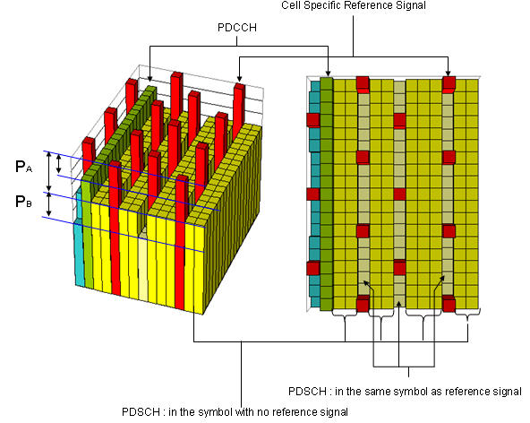
- The left block draws power as bar height over the resource grid. The tall red bars are the Cell Specific Reference Signal, the green bars behind them are PDCCH, and the low yellow bars are PDSCH.
- The two braces on the left edge mark the offsets. PA spans the upper gap and PB the lower one, and the blue lines running across the block are the levels they measure between.
- The right panel is the same grid seen flat, with frequency up the page and time across it. The red cells are the reference signal, the olive cells are PDSCH, and the teal column at the left edge is the control region.
- The two brackets underneath name the distinction that the rest of this page depends on. PDSCH in the same symbol as reference signal is one group, and PDSCH in the symbol with no reference signal is the other.
36.213 puts indices on that split. Table 5.2-2 lists the OFDM symbol indices within a slot that take each ratio. Symbols 0 and 4 take one ratio and symbols 1, 2, 3, 5 and 6 take the other, for one or two cell specific antenna ports under the normal cyclic prefix. With four antenna ports symbol 1 moves across as well, because a four port cell carries reference signal there too.
Flat power is the wrong default : the reference signal has to be received before anything else can be decoded, so it is the one channel that cannot sit at the same level as the rest.The split is by symbol, not by channel : the same PDSCH takes one power in a symbol that carries reference signal and another in a symbol that does not.36.213 fixes which symbols are which : Table 5.2-2 lists them by index, so nothing about the split is left to the implementation.
Where do the two offsets come from ?
One offset is a property of the cell and the other is a property of the UE. That difference decides which message carries each of them, and the two decodes below are what the difference looks like on the air.
Power offset between PDSCH channel in the symbols with reference signal and PDSCH channel in the symbols without reference signal (P_B) is specified in SIB2 as follows.
Capture : a SIB2 as one network sent it. Nothing in it has been corrected against a specification.
            +-sib-TypeAndInfo ::= SEQUENCE OF SIZE(1..maxSIB[32]) [1]
            | +- ::= CHOICE [sib2]
            |   +-sib2 ::= SEQUENCE [00]
            |     +-ac-BarringInfo ::= SEQUENCE OPTIONAL:Omit
            |     +-radioResourceConfigCommon ::= SEQUENCE
            |     | +-rach-Config ::= SEQUENCE
            |     | +-bcch-Config ::= SEQUENCE
            |     | +-pcch-Config ::= SEQUENCE
            |     | +-prach-Config ::= SEQUENCE
            |     | +-pdsch-Config ::= SEQUENCE
            |     | | +-referenceSignalPower ::= INTEGER (-60..50) [18]
            |     | | +-p-b ::= INTEGER (0..3) [0]
- The capture is a SIB2, so everything in it is cell specific. The tree runs down through radioResourceConfigCommon to pdsch-Config.
- Two fields there matter, and both are coloured red. The field referenceSignalPower reads 18, and p-b reads 0.
- 36.331 gives referenceSignalPower in dBm, as the downlink reference signal EPRE, so the 18 is an absolute power. p-b is an index into 36.213 Table 5.2-1, so the 0 is not a power at all.
Power offset between the Reference Signal and PDSCH channel in the symbols without reference signal (P_A) is specified in RRC Connection Setup as follows. P_A is UE specific power offset. This is why this is specified by RRC Connection Setup message.
Capture : an RRC Connection Setup as one network sent it. Nothing in it has been corrected against a specification.
          +-c1 ::= CHOICE [rrcConnectionSetup-r8]
            +-rrcConnectionSetup-r8 ::= SEQUENCE [0]
              +-radioResourceConfigDedicated ::= SEQUENCE [100101]
              | +-srb-ToAddModList ::= SEQUENCE OF SIZE(1..2) [1] OPTIONAL:Exist
              | +-drb-ToAddModList ::= SEQUENCE OF OPTIONAL:Omit
              | +-drb-ToReleaseList ::= SEQUENCE OF OPTIONAL:Omit
              | +-mac-MainConfig ::= CHOICE [explicitValue] OPTIONAL:Exist
              | +-sps-Config ::= SEQUENCE OPTIONAL:Omit
              | +-physicalConfigDedicated ::= SEQUENCE [1111001011] OPTIONAL:Exist
              |   +-pdsch-ConfigDedicated ::= SEQUENCE OPTIONAL:Exist
              |   | +-p-a ::= ENUMERATED [dB-3]
              |   +-pucch-ConfigDedicated ::= SEQUENCE [0] OPTIONAL:Exist
              |   +-pusch-ConfigDedicated ::= SEQUENCE OPTIONAL:Exist
              |   +-uplinkPowerControlDedicated ::= SEQUENCE [1] OPTIONAL:Exist
              |   +-tpc-PDCCH-ConfigPUCCH ::= CHOICE OPTIONAL:Omit
              |   +-tpc-PDCCH-ConfigPUSCH ::= CHOICE OPTIONAL:Omit
              |   +-cqi-ReportConfig ::= SEQUENCE [10] OPTIONAL:Exist
              |   +-soundingRS-UL-ConfigDedicated ::= CHOICE OPTIONAL:Omit
              |   +-antennaInfo ::= CHOICE [defaultValue] OPTIONAL:Exist
              |   +-schedulingRequestConfig ::= CHOICE [setup] OPTIONAL:Exist
              +-nonCriticalExtension ::= SEQUENCE OPTIONAL:Omit
- The second capture is an RRC Connection Setup, so it is addressed to one UE. The tree runs through radioResourceConfigDedicated to physicalConfigDedicated and then to pdsch-ConfigDedicated.
- One field is coloured red there. p-a reads dB-3, and 36.331 defines it as an enumerated value rather than a number, where dB-3 means -3 dB.
Following is based on
PDSCH-ConfigCommon ::=		SEQUENCE {
	referenceSignalPower				INTEGER (-60..50),
	p-b									INTEGER (0..3)
}

PDSCH-ConfigDedicated::=		SEQUENCE {
	p-a									ENUMERATED {
											dB-6, dB-4dot77, dB-3, dB-1dot77,
											dB0, dB1, dB2, dB3}
}
Both structures still read this way in 36.331 v19.3.0, so the two captures are current for the fields they show.
The names say where each offset lives. p-b sits in PDSCH-ConfigCommon, which is broadcast in SIB2, and p-a sits in PDSCH-ConfigDedicated, which is not. A cell therefore has one p-b and as many values of p-a as it has connected UEs.
The ranges differ for the same reason. The p-b field is an INTEGER from 0 to 3, because it only selects a row of a table. The p-a field is an enumeration of eight decibel values, from dB-6 to dB3, because it is a decibel offset and the useful values are not evenly spaced.
p-b is cell wide and p-a is per UE : one arrives in a broadcast SIB and the other in a dedicated RRC message.Only one of the two is a power : referenceSignalPower is in dBm, p-a is in dB, and p-b is an index with no unit at all.Neither capture was touched : both are records of what one network sent, so the values stand as they were decoded.
How do the two offsets become EPRE ratios ?
The UE does not use p-a and p-b directly. 36.213 turns them into two ratios of PDSCH energy per resource element to reference signal energy per resource element, and the two screenshots below are the rules that do it.
In Physical Layer performance test, we set Rho A, Rho B as a test condition and the relationship between Rho A/Rho B and P_a/P-b is as follows (from 3GPP 36.213).

- The screenshot is 36.213 clause 5.2, and it gives two cases that differ by one term.
- The first case adds 10 log10(2) to the offset. It applies only when the PDSCH uses precoding for transmit diversity with four cell specific antenna ports.
- The second case is everything else, and there the ratio is δpower-offset plus PA alone.
- δpower-offset is 0 dB for every transmission scheme except multi user MIMO, so for an ordinary configuration the ratio is simply PA.
Normally P_B is specified first by SIB2 and P_A is determined by following table and specified in RRC message (e.g, RRC Connection Setup, RRC Connection Reconfiguration) according to following table from 3GPP 36.213.
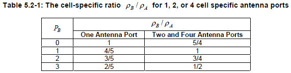
- The table is indexed by PB down the left and by the number of cell specific antenna ports across the top.
- One antenna port gives 1, 4/5, 3/5 and 2/5 as PB runs from 0 to 3. Two and four ports give 5/4, 1, 3/4 and 1/2.
- One entry is coloured blue. A PB of 1 with two or four ports gives a ratio of exactly 1, which is the configuration where both groups of symbols carry the same PDSCH power.
- The entries are power ratios rather than decibel values. A 1 means no difference, and a 1/2 means 3 dB down.
Table 5.2-1 reads the same in 36.213 v19.4.0 as it does in the screenshot. The clause around it has grown. A Release 12 UE can be given a second offset in servCellp-a, and a Release 13 SC-MTCH carries a p-a of its own. A Release 14 UE configured for multiuser superposition transmission takes p-a-must instead, when the grant says interference is present. The screenshot is the Release 8 case, and that case still governs an ordinary unicast PDSCH.
The offsets are inputs, not answers : 36.213 turns p-a into ρA and p-b into the ratio between ρB and ρA.Four antenna ports carry an extra term : transmit diversity on four cell specific ports adds 10 log10(2), which is 3 dB, on top of the offset.A ratio of 1 is a real configuration : p-b of 1 on a two or four port cell leaves the two groups of symbols at the same PDSCH power.
Examples :
The table below pairs a transmission mode with the p-a and p-b that normally go with it, and with the channel powers a tester would then measure. Reading the last column against the first two is the quickest check that a configuration is doing what it should.
Following is a couple of typical p-a, p-b configuration that we normally see. For further details, refer to 36.213 5.2 Downlink power allocation
|
Transmission Mode |
p-a |
p-b |
Example of Channel Power(dBm/15Khz) |
|
TM1 |
dB0 |
0 |
RS = -55, PCFICH=-55, PHICH=-55, PDSCH =-55 |
|
TM3 (2x2) |
dB-3 |
1 |
RS = -55, PCFICH=-58, PHICH=-58, PDSCH =-58 |
|
TM3 (4x4) |
dB-6 |
1 |
RS = -55, PCFICH=-58, PHICH=-58, PDSCH =-58 |
|
TM3 (4x2) |
dB-6 |
1 |
RS = -55, PCFICH=-58, PHICH=-58, PDSCH =-58 |
- The first row is the flat case. TM1 with p-a of dB0 and p-b of 0 leaves every channel at -55, and there is no offset to find anywhere in it.
- The other three rows put PDSCH, PCFICH and PHICH 3 dB below the reference signal, and the reference signal itself stays at -55 in every row.
- p-b is 1 in all three of those rows. On a two or four port cell, 36.213 Table 5.2-1 turns that into a ratio of 1, so both groups of symbols carry the same PDSCH power.
- dB-3 is 10 log10 of one half and dB-6 is 10 log10 of one quarter, which is what sharing one power budget between two or between four antenna ports gives.
The two dB-6 rows need explaining, because -55 minus 6 is -61 and the table says -58. The first bullet of the 36.213 screenshot above is what reconciles them. With four cell specific antenna ports and precoding for transmit diversity, 36.213 adds 10 log10(2) to the offset, so a p-a of dB-6 produces a ratio of -3 dB rather than -6 dB.
That is why the last column is the same for a two port and a four port cell. The offset differs, the extra term differs, and the measured PDSCH power is the same in both.
The measured power is the offset plus the rule : p-a alone does not predict the last column, and on a four port cell it differs by 3 dB.The reference signal is the fixed point : it reads -55 in every row, and every other channel is quoted against it.A flat configuration is a valid one : TM1 with dB0 and 0 puts every channel at one level, which is where this page started.
Reference
The documents below are the sources for the two ratios and for the parameters that feed them. A version is named only where the text was read in that version.
- 36.213 : 3GPP - E-UTRA; Physical layer procedures, v19.4.0. Clause 5.2 is downlink power allocation, Table 5.2-1 gives the cell specific ratio, and Table 5.2-2 lists which OFDM symbol index takes which ratio.
- 36.331 : 3GPP - E-UTRA; Radio Resource Control (RRC) protocol specification, v19.3.0. The source of the ASN.1 tile above and of the field descriptions for referenceSignalPower, p-a and p-b.