As the term ICIC stands for, it is a type of technology which is designed to reduce the interference created by two or more cells.
- Where the interference is worst
- Approaches to Solution
- Possible Solutions
- Channel Configuration for eICIC
- RRC for eICIC
- How the two eNBs agree the pattern
- Test Specification
- Reference - 3GPP
- Reference - General
Where the interference is worst
Interference is always present, so the useful question is where it decides the outcome. The three cases below are the ones 3GPP built machinery for, and they are not variations on one another. What changes between them is which cell is the victim and which is the aggressor.
In which situation do you think a UE suffer most seriously from this kind of interference ? We can easily think of following cases.
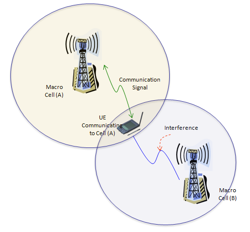
- Case 1 : UE is in cell boundary of a cell. In this case, the signal from neibour cell can act as interferer. In this case, signal strength from serving cell tends to be very weak and at the same time SNR would be very poor not only because of the weak serving cell signal but also because of the interference.
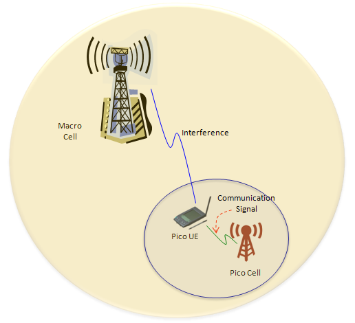
- Case 2 : UE is under a coverage of a femto or pico cell. In this case, the Macro cells around those pico/femto cell or other pico/femto cell can act as interferer. In this case, the signal strength from serving cell may not be such a weak, but SNR tend to be poorer due to the interference.
- Case 3 : UE is located close to a CSG cell, but it is not the CSG member of that cell. In this case, the signal from the CSG cell act as very strong (sometimes stronger than the serving cell itself) and can be very problemetic (This would be why 3GPP 36.300 take CSG as an important criteria for ICIC/eICIC implementation).
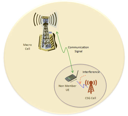
The macro case puts the UE between two equals : the serving cell and the interferer are both macro cells, and the UE sits where the two circles overlap.The pico case nests one cell inside the other : the drawing puts the pico circle wholly within the macro, so the interferer surrounds the victim.The CSG case reverses the arrows : the UE is served by the distant macro and interfered by the small cell at its feet.The victim is not always the small cell : compare the green communication arrows in the last two pictures, which point in opposite directions.
That reversal is why 36.300 keeps the two as separate scenarios. Annex K.1.2 has the macro give up subframes so a pico cell can serve a UE it has taken on. Annex K.1.1 has the CSG cell give up subframes so the macro can keep serving a UE standing right beside it. The mechanism is identical, and only the direction changes.
Three cases, two directions : the macro protects the pico, and the CSG cell protects the macro.36.300 names both in Annex K : K.1.1 covers the CSG scenario and K.1.2 the pico scenario.Every case is one carrier : two cells on different frequencies would need none of this.
Approaches to Solution
There has been a lot of discussions about the solutions. Following is a kind of baseline idea on the approaches to solution from R1-104942. Some of them has been adopted in 3GPP specification as of now (36.300), but some of them are not reflected in the spec or still need further clarification. But I quoted the full list from R1-104942 to give you broader idea on possible solution. For further details, refere to R1-104942. I think the items marked in blue is reflected in 3GPP spec now.
- Consider power control and time domain solution as baseline solutions
- Frequency domain solution is not precluded.
- More concrete proposal of each solution should be provided
- Ensure backwards compatibility to Rel8/9 UE
- Strive for at least one common TDD and FDD solution whenever possible
- Feedback from other WGs should be consolidated to make decision
- Applicability of macro-pico scenario is FFS
Most of that list is settled now, and 36.300 says which way each item went. Clause 16.1.5.0 gives ICIC exactly two components, a frequency domain one and a time domain one. Power control is not among them. The backward compatibility item survived intact. The same clause has the eNB keep transmitting the necessary control channels, the physical signals and the System Information, even in an almost blank subframe.
The common FDD and TDD item survived in a particular way. One mechanism covers both duplex modes, and the only difference is the length of the bitmap that carries the pattern. 36.423 gives 40 bits for FDD, and 20, 60 or 70 for TDD, with one length for each group of uplink and downlink configurations.
Two of the three baseline domains reached the specification : 36.300 clause 16.1.5.0 lists a frequency domain component and a time domain one, and no power control component.Backward compatibility was kept : an almost blank subframe still carries the control channels, the physical signals and the System Information.One mechanism covers both duplex modes : FDD and TDD differ only in how long the pattern bitmap is.The blue marks are the reading at the time : the paragraph above says so, and the specification has moved since.
Possible Solutions
As you know, LTE signal (actually most of the communication signal) has two components. Time domain component and frequency domain components. So the interference can occur in both domains.
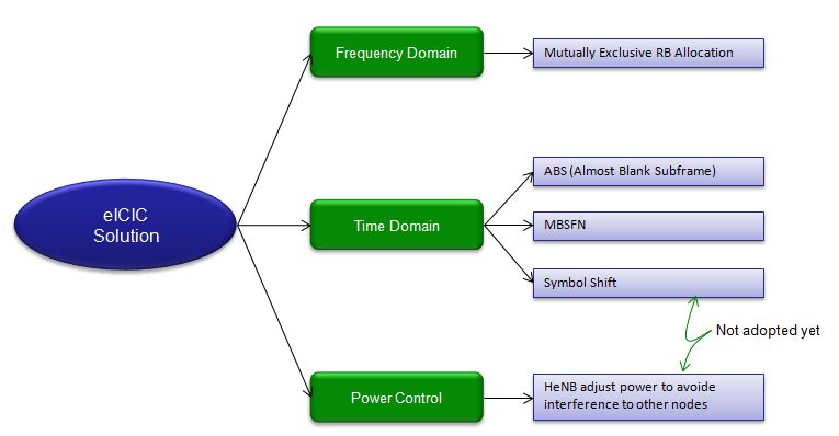
Three branches leave the eICIC Solution node : Frequency Domain, Time Domain and Power Control.Time Domain is the branch that grew : it carries ABS, MBSFN and Symbol Shift.Frequency Domain has a single leaf : mutually exclusive resource block allocation.Two leaves carry a note : the double headed green arrow marks Symbol Shift and the HeNB power leaf as not adopted yet.
Now we have to think about how we can reduce the interference on Frequency Domain and Time Domain.
In Frequency Domain, one way to reduce the interference would be to allocate the resource blocks from multiple neighbouring cells in such a way that the allocated resource blocks does not overlap each other. For example, if a cell (e.g, serving cell) allocated RB0~10 for a UE, let neighbouring cell allocate RB 15~20 for another UE.
In Time Domain, one way to reduce the interference is that a cell (e.g, serving cell) stop transmitting at a certain subframe so that other cell (e.g, a femto/pico cell) can transmit the signal during that period. But sometimes completely stoping the signal transmission would cause some issues. So it would be recommended to transmit the signal in very low power in stead of completely stopping the transmission. These subframe with very low signal power is called 'Almost Blank Subframe (ABS)'.
What I described above can be illustrated as shown below. (For further details on Channels being transmitted in ABS frame in various situation, refer to A.3.4 ABS Transmission Configurations of 36.133)
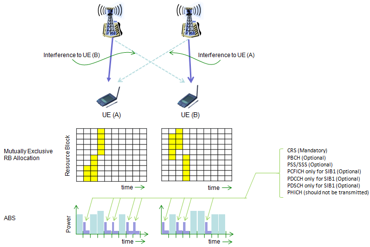
Does this illustration make sense to you ? First think on your own about what this illustration indicate before you read the following.
Now look at the upper track figure showing the resource grid and focus on the yellow color resource blocks. Left one is the resource grid for eNB1 (left) and Right one is the resource grid for eNB2 (right). The yellow color resource block are the ones that user data is being transmitted. If you compare the yellow color Resource block of the two resource grid, the position never overlaps each other. It means for each symbol the user data from two different eNB is being transmitted in different subcarrier (different frequency) so they do not interfere each other.
Now let look at the lower track. These plot represents the cell power for each subframe (time domain). The tall/wide bars represents the subframe where user data is being transmitted in high power and the small/narrow bars represents ABS subframe that carries only fundamental channels without any user data. In this plot as well, you would notice that both cell transmit user data in certain symbols, but the subframe carrying the user data does not overlap each other.
These two tracks of figure shows fundamental mechanism of eICIC. Upper one shows how to reduce the interference in frequency domain and Lower one shows how to reduce the interference in time domain. In current 3GPP test specification, only time domain method is adopted but frequency domain method can be applied depending on situation.
One part of that illustration the paragraphs above pass over is the callout on the right. Green lines run from the low power subframes to a list, and the list is the useful half of the picture. It says what an almost blank subframe still carries.
CRS is mandatory : the cell specific reference signals go out in every almost blank subframe, which is what keeps the cell detectable.PBCH and PSS/SSS are optional : the cell may keep broadcasting them or leave them out.PCFICH, PDCCH and PDSCH appear only for SIB1 : system information gets through, and user data does not.PHICH is the one to leave out : the list marks it as a channel that should not be transmitted.
Those seven lines are the difference between an almost blank subframe and a silent one. A Release 8 UE has never heard of eICIC. It still finds the cell, still reads the system information and still measures the cell, because everything it needs is on that list.
Channel Configuration for eICIC
As I mentioned above, the most important way to implement eICIC as of now is to use ABS (Almost Blank Symbol). The ABS is not a simple turning off certain channels. It is specific composition letting the most fundamental channels (e.g, Sync Channel and Confrol Channel) still detectable by UEs but minimze the interference. Following table shows some example of ABS channel composition defined in 3GPP specification. But in real application, these composition would vary depending on situation.
More detailed channel configuration of non-ABS and ABS subframes with various antenna configuaration and use/non-use of MBSFN is as shown below. (This is based on 36.133)
|
NON-MBSFN |
MBSFN |
||||||||||||
|
A.3.4.1.1 |
A.3.4.1.2 |
A.3.4.1.2-2 |
A.3.4.2.1-1 |
A.3.4.2.2-1 |
A.3.4.2.2-2 |
||||||||
|
Chan |
Param |
N_ABS |
ABS |
N_ABS |
ABS |
N_ABS |
ABS |
N_ABS |
ABS |
N_ABS |
ABS |
N_ABS |
ABS |
|
PBCH |
RA |
0 |
0 |
-3 |
-inf |
-3 |
-inf |
0 |
N/A |
-3 |
N/A |
-3 |
N/A |
|
RB |
0 |
0 |
-3 |
-inf |
-3 |
-inf |
0 |
N/A |
-3 |
N/A |
-3 |
N/A |
|
|
PSS |
RA |
0 |
0 |
-3 |
-3 |
-3 |
-3 |
0 |
N/A |
-3 |
N/A |
-3 |
N/A |
|
SSS |
RA |
0 |
0 |
-3 |
-3 |
-3 |
-3 |
0 |
N/A |
-3 |
N/A |
-3 |
N/A |
|
PCFICH |
RB |
0 |
0/-inf |
1 |
-inf |
1 |
-inf |
0 |
-inf |
1 |
-inf |
1 |
-inf |
|
PHICH |
RA |
0 |
-inf |
-3 |
-inf |
-3 |
-inf |
0 |
-inf |
-3 |
-inf |
-3 |
-inf |
|
RB |
0 |
-inf |
-3 |
-inf |
-3 |
-inf |
0 |
-inf |
-3 |
-inf |
-3 |
-inf |
|
|
PDCCH |
RA |
0 |
0 |
1 |
-inf |
-3 |
-inf |
0 |
-inf |
1 |
-inf |
-3 |
-inf |
|
RB |
0 |
0 |
1 |
-inf |
-3 |
-inf |
0 |
-inf |
1 |
-inf |
-3 |
-inf |
|
|
PDSCH |
RA |
0 |
0 |
-3 |
-inf |
-3 |
-inf |
0 |
-inf |
-3 |
-inf |
-3 |
-inf |
|
RB |
0 |
0 |
-3 |
-inf |
-3 |
-inf |
0 |
-inf |
-3 |
-inf |
-3 |
-inf |
|
|
OCNG |
RA |
0 |
-inf |
-3 |
-inf |
-3 |
-inf |
0 |
-inf |
-3 |
-inf |
-3 |
-inf |
|
RB |
0 |
-inf |
-3 |
-inf |
-3 |
-inf |
0 |
-inf |
-3 |
-inf |
-3 |
-inf |
|
The above table is a consolidated table of following tables in 36.133
Table A.3.4.1.1 Non-MBSFN ABS Transmission, 1x2 antenna with PBCH
Table A.3.4.1.2 Non-MBSFN ABS Transmission, 2x2 antenna without PBCH
Table A.3.4.1.2-2: Transmission configuration #2 with non-MBSFN ABS, 2x2 without PBCH
Table A.3.4.2.1-1: Transmission configuration with MBSFN ABS, 1x2
Table A.3.4.2.2-1: Transmission configuration #1 with MBSFN ABS, 2x2
Table A.3.4.2.2-2: Transmission configuration # 2 with MBSFN ABS, 2x2
Two axes run through those six tables, and naming them makes the one above easier to read. The first is the antenna configuration, 1x2 or 2x2, which sets how many reference signal ports the subframe has to carry. The second is whether the almost blank subframe is an MBSFN subframe.
The MBSFN case has its own half of the annex. 36.300 clause 16.1.5.0 allows MBSFN subframes to be folded into an ABS pattern, but not when those subframes already carry MBMS or positioning. An MBSFN subframe also has a shortened control region to begin with, so it starts closer to blank than an ordinary subframe does.
The table consolidates six from 36.133 : Annex A.3.4.1.x for the non-MBSFN cases and A.3.4.2.x for the MBSFN ones.Two axes organise them : the antenna configuration, and whether the ABS is an MBSFN subframe.An MBSFN subframe can be an ABS : 36.300 allows it, except where that subframe already carries MBMS or positioning.An ABS is a composition, not a silence : the paragraph above makes the point and the table gives the detail.
RRC for eICIC
In terms of signaling point of view, eICIC is a dedicated channel process. It means a specific configuration information need to be exchanged between UE and the network via signaling messages for each specific UEs.
The first step is for a UE to inform the network of whether it support eICIC or not. This information is carried by Feature Group Indicator (FGI) in UE Capability Information message as indicated below.
FGI in UE Capability Information
One bit in the capability message settles whether any of this can be configured at all. The decode below is a capture from one UE, and it is worth reading for its values rather than its shape. Indicator 115 is the eICIC one.
A decoded Feature Group Indicator field,
featureGroupIndRel10-r10: 00000000 [bit length 32, 0000 0000  0000 0000  0000 0000  0000 0000 decimal value 0]
         0... .... = Indicator 101: DMRS with OCC (orthogonal cover code) and SGH (sequence group hopping) disabling - Not supported
         .0.. .... = Indicator 102: Trigger type 1 SRS (aperiodic SRS) transmission (Up to X ports) - Not supported
         ..0. .... = Indicator 103: PDSCH TM9 when up to 4 CSI reference signal ports are configured - Not supported
         ...0 .... = Indicator 104: PDSCH TM9 for TDD when 8 CSI reference signal ports are configured - Not supported
         .... 0... = Indicator 105: PUCCH RM2-0 when PDSCH TM9 is configured and RM2-1 when PDSCH TM9
                                    and up to 4 CSI reference signal ports are configured - Not supported
         .... .0.. = Indicator 106: PUCCH RM2-1 when PDSCH TM9 and 8 CSI reference signal ports are configured - Not supported
         .... ..0. = Indicator 107: PUSCH RM2-0 when PDSCH TM9 is configured and RM2-2 when PDSCH TM9 and
                                    up to 4 CSI reference signal ports are configured - Not supported
         .... ...0 = Indicator 108: PUSCH RM2-2 when PDSCH TM9 and 8 CSI reference signal ports are configured - Not supported
         0... .... = Indicator 109: PUCCH RM1-1 submode 1 - Not supported
         .0.. .... = Indicator 110: PUCCH RM1-1 submode 2 - Not supported
         ..0. .... = Indicator 111: Measurement reporting trigger Event A6 - Not supported
         ...0 .... = Indicator 112: SCell addition within the Handover to EUTRA procedure - Not supported
         .... 0... = Indicator 113: Trigger type 0 SRS (periodic SRS) transmission on X Serving Cells - Not supported
         .... .0.. = Indicator 114: Reporting of both UTRA CPICH RSCP and Ec/N0 in a Measurement Report - Not supported
         .... ..0. = Indicator 115: Time domain ICIC RLM/RRM / ICIC RRM / ICIC CSI measurement sf restriction
                                    for the serving cell / neighbour cells - Not supported
         .... ...0 = Indicator 116: Relative transmit phase continuity for spatial multiplexing in UL - Not supported
Read the capture and the answer is no. The field arrives as 32 zero bits, the decoder spells out decimal value 0, and every indicator from 101 to 116 comes back Not supported. Indicator 115 is among them, and it is the one that covers time domain ICIC measurement restriction for the serving cell and the neighbour cells.
A network reading this message would therefore configure none of the patterns in the rest of this section. The capture is useful precisely because it shows the negative case, which is what a UE without the feature looks like on the wire.
subframePattern
If network confirms that a specific UE is capable of eICIC, it can inform UE of more specific information about its eICIC configuration. One example is about measurement subframe information as shown below. With this information, network tells a UE "I am configuring this and this and this subframe as ABS to reduce the interference, so don't try any measurement for such subframe".
This IE represents "Time domain measurement resource restriction pattern for the PCell measurements (RSRP, RSRQ and the radio link monitoring). (See 36.331)
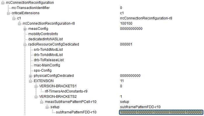
The highlighted value is worth doing the arithmetic on. It reads 10000000 five times over, which is 40 bits, and 40 bits is what 36.331 allows for FDD. The pattern therefore marks one subframe in every eight, five of them across the four radio frames the bitmap spans.
Following is based on
MeasSubframePattern-r10 ::=         CHOICE {
    subframePatternFDD-r10              BIT STRING (SIZE (40)),
    subframePatternTDD-r10              CHOICE {
        subframeConfig1-5-r10               BIT STRING (SIZE (20)),
        subframeConfig0-r10                 BIT STRING (SIZE (70)),
        subframeConfig6-r10                 BIT STRING (SIZE (60)),
        ...
    },
    ...
}
36.331 also fixes what a 1 means and where the pattern starts. The leftmost bit is subframe 0 of the radio frame where SFN mod x is 0, with x the bit string length divided by 10. A 1 denotes that the subframe is used. For a 40 bit FDD pattern that makes the cycle four radio frames.
csi-MeasSubframeSet
Channel quality reporting gets a restriction of its own, separate from the two above. The reason is that a UE measuring interference has to know which kind of subframe it measured in. Without that, the number it reports means nothing.
You can send a similar information about csi-Measurement as well by following information element. Here you see two different sets of csi-MeasSubframetSet.
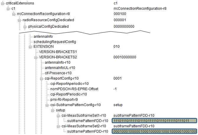
The two values below it are the point of having two sets. One is dense in ones and the other is sparse, so the UE reports channel quality twice for the same cell. 36.300 clause 16.1.5.1 says the network normally picks the two so that they see different interference, one set on the protected subframes and the other off them.
Note 1 : cqi-pmi-ConfigIndex (According to 36.331)
If subframe patterns for CSI (CQI/PMI/PTI/RI) reporting are configured (i.e. csi-SubframePatternConfig is configured), the parameter applies to the subframe pattern corresponding to csi-MeasSubframeSet1.
Note 2 : cqi-pmi-ConfigIndex2 (According to 36.331)
The parameter applies to the subframe pattern corresponding to csi-MeasSubframeSet2
measSubframePatternConfigNeigh
This IE represents "Time domain measurement resource restriction pattern applicable to neighbour cell RSRP and RSRQ measurements on the carrier frequency indicated by carrierFreq. For cells in measSubframeCellList the UE shall assume that the subframes indicated by measSubframePatternNeigh are non-MBSFN subframes." (See 36.331)
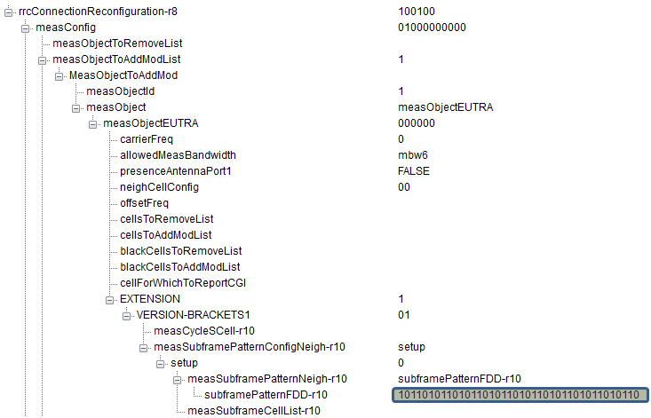
Put the three decodes side by side and a pattern appears in where they sit rather than in what they carry. The PCell restriction and the CSI sets both hang off physicalConfigDedicated, inside the radio resource configuration. The neighbour restriction hangs off measObjectEUTRA instead, inside the measurement configuration.
That split follows the job each one does. A measurement object already names a carrier frequency and a list of cells, which is exactly the scope 36.300 gives the neighbour pattern. The measSubframeCellList visible under it in the decode is that list.
Following is based on
MeasSubframePatternConfigNeigh-r10 ::=  CHOICE {
    release                                 NULL,
    setup                                   SEQUENCE {
        measSubframePatternNeigh-r10            MeasSubframePattern-r10,
        measSubframeCellList-r10                MeasSubframeCellList-r10    OPTIONAL   -- Cond always
    }
}

MeasSubframeCellList-r10 ::=        SEQUENCE (SIZE (1..maxCellMeas)) OF PhysCellIdRange
The capability bit comes first : Indicator 115 decides whether the network may configure any of the patterns at all.Three patterns, three places in the message : the PCell one and the CSI sets in physicalConfigDedicated, the neighbour one in measObjectEUTRA.They match the three 36.300 defines : clause 16.1.5.1 lists an RRM and RLM restriction for the PCell, an RRM restriction for named neighbours, and a CSI restriction.The bitmap is the same element throughout : MeasSubframePattern-r10, 40 bits for FDD in every one of the three.
How the two eNBs agree the pattern
Everything above happens between the network and one UE. The pattern itself was agreed earlier, between two eNBs, and the UE never sees that exchange. It runs over X2, and 36.300 puts it inside the Load Indication procedure.
Clause 20.2.2.6 gives that procedure the job in one sentence. When the time domain method is in use, an eNB signals its almost blank subframe patterns to its neighbours, so a receiving eNB can use those subframes with less interference. 36.423 defines the element that carries them.
Clause 9.2.54 calls it ABS Information. For FDD it is a bit string of 40 bits, one per downlink subframe, where 1 marks an ABS and 0 marks a normal subframe. Reading starts at subframe 0 of the radio frame where SFN is 0, and the pattern repeats without a gap. The same element also carries the number of cell specific antenna ports, and a measurement subset.
That measurement subset is the join between this section and the one above. It is a subset of the ABS pattern, and 36.423 says it is there to configure measurements towards the UE. An eNB sends one bitmap to its neighbour over X2, and that neighbour sends a bitmap to its UEs over RRC. The two have the same shape, and for FDD both run to 40 bits.
Information travels back as well. Clause 9.2.58 defines ABS Status, whose DL ABS status field is an integer from 0 to 100. It reports the percentage of the protected resources the victim cell actually used, and the aggressor reads it to decide whether to keep the pattern. An eNB that wants a pattern rather than waiting for one sends the Invoke Indication element of clause 9.2.55.
The pattern is agreed over X2 first : 36.300 clause 20.2.2.6 puts it in the Load Indication procedure.One bitmap shape, two interfaces : 40 bits for FDD in the X2 element, and 40 bits for FDD in the RRC pattern.The measurement subset is the handover point : a subset of the ABS pattern, meant for configuring the UE.The victim reports how much it used : DL ABS status is a percentage, and it tells the aggressor whether the protected subframes are being used.An eNB can ask rather than wait : the Invoke Indication element requests an ABS Information from a neighbour.
Test Specification
Following is 3GPP Test cases to test eICIC, but as of the latest release (ETSI TS 136 521 V11.2.0 (2013-10)), the specification is not finalized yet. So just try to understand overall test logic.
Following is from 36.508
- 4.6.6 Measurement information elements
Following is from 36.521-1
- 36.521-1 : 8.2.1.2.3_C FDD PDSCH Transmit diversity 2x2 for eICIC
- 36.521-1 : 8.2.1.3.3_C FDD FDD PDSCH Open Loop Spatial Multiplexing 2x2 for eICIC
- 36.521-1 : 8.2.2.2.3_C TDD PDSCH Transmit diversity 2x2 for eICIC
- 36.521-1 : 8.2.2.3.3_C TDD PDSCH Open Loop Spatial Multiplexing 2x2 for eICIC
Following is from 36.521-3
- 36.521-3 : 7.3.9 E-UTRAN FDD Radio Link Monitoring Test for Out-of-sync under Time Domain Measurement Resource Restriction with Non MBSFN ABS (eICIC)
- 36.521-3 : 7.3.10 E-UTRAN TDD Radio Link Monitoring Test for Out-of-sync under Time Domain Measurement Resource Restriction with Non MBSFN ABS (eICIC) with Non MBSFN ABS (eICIC)
- 36.521-3 : 7.3.11 E-UTRAN FDD Radio Link Monitoring Test for In-sync under Time Domain Measurement Resource Restriction with Non MBSFN ABS(eICIC)
Following is from 36.523-1
- 8.3.1.19 eICIC/ Measurement configuration control and reporting / CSI change
- 8.3.1.20 eICIC / Measurement configuration control and reporting / Event A3 / RSRP and RSRQ measurement / Neighbour ABS
- 8.3.1.21 eICIC / Measurement configuration control and reporting / Event A3 Handover / Neighbour RSRP measurement configuration change
- 8.3.1.28 eICIC / Measurement configuration control and reporting / Event A3 / RSRP and RSRQ measurement / Serving ABS
The four specifications in that list divide the work in a way worth noticing. 36.508 supplies the common measurement information elements the other three reuse. 36.521-1 tests the radio, on the transmission modes an ABS has to keep working under. 36.521-3 tests radio resource management, which is where a measurement restriction does its work. 36.523-1 tests the protocol.
The protocol list is the one that settles it. All four of its cases are measurement configuration and reporting, and none is about transmitting an ABS. From the UE side eICIC is a measurement feature, which is where the capability bit and the three patterns above both point.
Four specifications, four jobs : common information elements, RF, radio resource management and protocol.Every protocol case is a measurement case : all four 36.523-1 items are measurement configuration and reporting.The UE never transmits an ABS : it is the eNB that goes quiet, and the UE is only told where to measure.The note above is dated : it was written while the conformance work was still open.
Reference - 3GPP
Actually eICIC is a huge topic covering from physical layer to signaling layer, and it is hard to describe all the details in this post. If you want to know further details of this technology, refer to the specification as summarized below. As you know, 3GPP TS specification is very dry.. it just say "Do this, Do that" and does not say anything about "why we need to do this ?". If you are interested more in technical background rather than dry instructions, I would recommend you to read TDocs first.
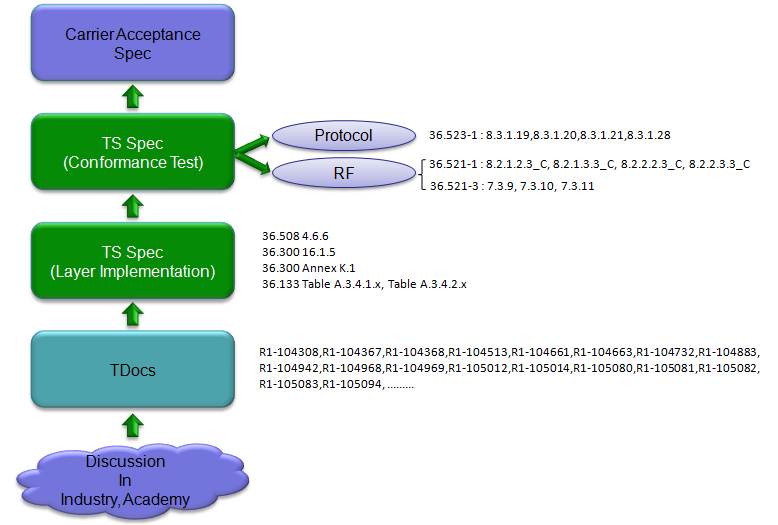
The chain runs bottom to top : discussion in industry and academia, then TDocs, then the implementation specifications, then conformance test, then carrier acceptance.R1-104942 sits in that TDoc list : the same document the approaches section further up quotes.The implementation layer names four places : 36.508 4.6.6, 36.300 16.1.5, 36.300 Annex K.1 and the 36.133 A.3.4 tables.Conformance splits in two : a Protocol branch pointing at 36.523-1, and an RF branch pointing at 36.521-1 and 36.521-3.
The specifications this page draws on, at the versions checked while it was last revised:
[1] 36.300 : 3GPP - E-UTRA and E-UTRAN; Overall description; Stage 2, v19.2.0. Clause 16.1.5 gives Inter-cell Interference Coordination and the almost blank subframe, clause 16.1.5.1 the three measurement restriction patterns, clause 20.2.2.6 the Load Indication procedure, and Annex K the two deployment scenarios.
[2] 36.331 : 3GPP - E-UTRA; Radio Resource Control, v19.3.0. MeasSubframePattern-r10 carries the bitmap, and MeasSubframePatternConfigNeigh-r10 carries it together with the cell list.
[3] 36.423 : 3GPP - E-UTRAN; X2 application protocol, v19.1.0. Clause 9.2.54 gives the ABS Information element, clause 9.2.55 the Invoke Indication and clause 9.2.58 the ABS Status report.
[4] 36.133 : 3GPP - E-UTRA; Requirements for support of radio resource management. Annex A.3.4 holds the six transmission configuration tables the table above consolidates.
Reference - General
Sound simple ?
If yout think it is too simple, I think I misled you by providing you with too high level picture. In engineering, Nothing is as simple as it sound -:).
If you want to go a little bit more details, please refer to following introduction. (I think this is better introduction than mine -:)
4G-LTE-Blogspot : ICIC and eICIC
If you want to go a little bit more details than the previous one, please refer to following introduction.
3G and 4G Wireless Blog : eICIC: Enhanced inter-cell interference coordination in 3GPP Release-10
If you want an extreme details, please refer to following article.
Bell-Lab : Algorithms for Enhanced Inter Cell Interference Coordination (eICIC) in LTE HetNets (If this link does not work, try this).
If you want in-depth material in more practical sense, please refer to following :
Mahmoud I. Kamel et al : Performance Evaluation of a Coordinated Time-Domain eICIC Framework based on ABSF in Heterogeneous LTE-Advanced Networks
For the offical 3GPP document, refer to 36.300 , 16.1.5 Inter-cell Interference Coordination (ICIC)
You can find some articles about eICIC (with test equipment and deployed network).