Reference to : TS 36.213 7.1.6 Resource allocation
Resource Allocation Type specifies the way in which the scheduler allocate resource blocks for each transmission. Just in terms of flexibility, the way to give the maximum flexibility of resource block allocation would be to use a string of a bit map (bit stream), each bit of which represent each resource block. This way you would achieve the maximum flexibility, but it would create too much complication of resource allocation process or too much data (too long bit map) to allocate the resources.
So LTE introduces a couple of resource allocation types and each of the resource allocation type uses a predefined procedures. There are three different resource allocation types in LTE, Resource Allocation Type 0, 1, 2.
|
DCI Format |
Possible Resource Allocation Type |
Memo |
|
1 |
Type 0 or Type 1 |
determined by resource allocation header field |
|
1A |
Type 2 |
|
|
1B |
Type 2 |
|
|
1C |
Type 2 |
|
|
1D |
Type 2 |
|
|
2 |
Type 0 or Type 1 |
determined by resource allocation header field |
|
2A |
Type 0 or Type 1 |
determined by resource allocation header field |
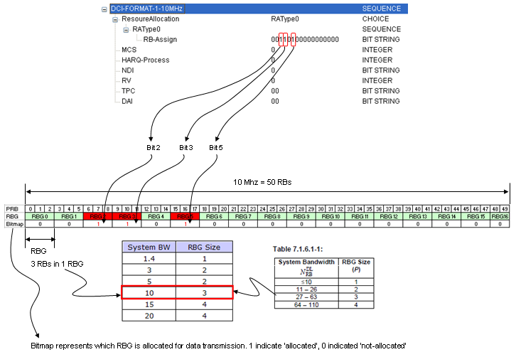
Resource Allocation Type 0 : This is the simplest way of allocation resources. First it divides resource blocks into multiples of groups. This resource block group is RBG(Resource Block Group) called. The number of resource block in each group varies depending on the system band width. It means RBG size gets different depending on the system bandwidth. The relationship between RBS size (the number of resouce block in a RBG) and the system bandwidth as follows.
|
System BW |
RBG Size |
|
1.4 |
1 |
|
3 |
2 |
|
5 |
2 |
|
10 |
3 |
|
15 |
4 |
|
20 |
4 |
Resource allocation type 0 allocate the resources using a bitmap and each bit represents one RBG.
The data hierachy in this type is "RB --> RGB" and the resource allocation is done at the level of RBG. Following is an example in RA Type 0 for 10 Mhz BW. One thing you have to notice here is each bit in the bitmap represents one RBG, not one RB.
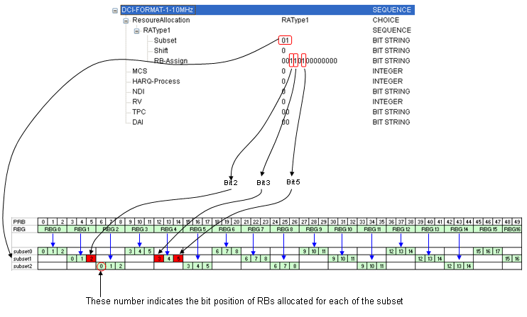
Resource Allocation Type 1 : I don't know how to explain about this type without using a well illustrated picture (I will try to create it later). Like in Resource Allocation Type 0, this RA type (Resource Allocation Type) is also using bitmap for the allocation, but in this RA type an additional layer was added. The new layer (hiearchy) is RBG Subset. So the overal hierarchy is "RB --> RBG --> RBG Subset" and the resource allocation is done at 'RBG Subset' level. One RBG Subset is made up of mulple RBGs. Exactly how many RBGs are in one RBG Subset varies depending on the bandwidth, but the number of RBs within a RBG is the same as number RBGs within an RBG Subset. Following is an example in RA Type 1 for 10 Mhz BW. Things you have to notice here are
-
Each bit in the bitmap represents RB.
-
Each RBG is allocated across multiple subsets as shown below.
-
The number of subsets is equal to the number of RBs within a RBG.
-
You can not allocate all RBs since there is no subset which can covers all RBs.
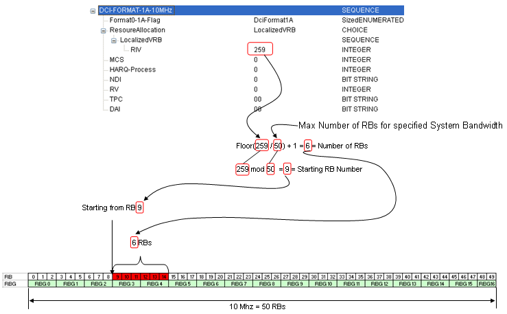
Resource Allocation Type 2 : In this case, network allocate a set of contiguous RBs. But this contiguous RB is "Virtual" concept, not the "Physical" concept. It means that even though MAC layer allocate the multiple contiguous RBs, they may not be aligned contiguously when it get transmitted at PHY layer. This means that there should be a rule/algorithm to convert this logical(virtual) RB allocation to physical RB allocation.
There are two type of the conversion, one is 'localized' and the other is 'distributed'. When you select 'localized', both virtuall allocation and physical allocation allocate RBs in contiguous way. When you select 'distributed', the virtual RB allocation is contiguous, but physical allocation is not contiguous (they are distributed over wider frequency ranges). Following is an example in RA Type 2 for 10 Mhz BW.