|
Mechanical Engineering : Tools : G-Code |
|||||||||||||||||||||||||||||||||||||||
|
G Code
G-Code is a kind of generic computer language that is designed to automate various CNC(Computer Numeric Control) machines like Mills or Lathes . Actually in many industries there are special kind of language or command set that are commonly used in the industry. For example, there is a specific language (or command set) that is used to control (or automate) phones. It is called AT command. As an another example, there is a specific language that is designed to control (or automate) various types of test and measurement equipment. It is called GPIB(General Purpose Interface Bus) command or SCPI(Standard Commands for Programmable Instrumentation).
Commend List
You can find the extensive description of all the G-Code from various source. Personally I think G-code (reprap.org) is one of the best document for me. I also put links to a couple of other good documents in Reference section.
Don't try to memorize or understand every command at once. It is almost impossible to memorize it and is not worth trying either, but it would be good to understand overall logics of the command. And then just pick an handfull of command that are most commonly used and understand those command throughly. Then you can easily understand other commands just by taking a quick look at the command document.
In this page, I would introduce only small set of command that are most commonly used.
< G command >
< M command >
G command and M commad
If you take a look at any G-Code document, you will see a huge set of command list but all of those commands would fall into one of two main categories : G command(G code) and M command (M code).
G stands for Geometry. As it implies, it is to move a tool to a specific position or in a specific geometric shape. M stands for Miscellaneous. It is related to various other operations not defined by G-code like speed change, tool change etc.
Typical Program Structure
There is no explictely required G code program structure, but practically many of the program would use several common patterns as I would like to introduce in this section.
< Type 1 >
G90 or G91 ; specify whether you want to apply relative positioning or absolute positioning G00 ; move the tool to a specific location G01 or G02 or G03 ; carve (mill) the object along the geometric path (e.g, along the straight line or arc)
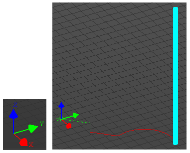
Ex 01 > G91 ; set to the relative positioning. The X,Y,Z from now on will be interpreted as a displacement G21 ; set the unit to mm G00 X2 Y2 ; move the tool to 2mm along X axis, 2mm along Y axis from the current position G01 Z-1 ; move the tool to 1mm along Z axis in negative direction G01 X2 Y2 ; move the tool to 2mm along X axis, 2mm along Y axis from the current position G02 X4 Y4 R3 ; move the tool to 2mm along X axis, 2mm along Y axis from the current position ; along the arc with the radius of 3 mm
The result of this program simulated in jViewer is shown below(the green dotted line and red line shows the path the tool has passed and the cyan-colored bar is the tool that moves by the code).
Free Tools
G code command is designed to be very simple and would be easily processed even by the simple machine that does not have strong programming capability, but it is not so human friendly. You may not easily understand the meaning of each command without really trying it on your own. However getting access to real CNC machine to try the code would not be easy. Fortunately there are various kinds of software tools that interpret the G-code and display the path moved by the tool or simulate a real CNC machine in 3G simulation. You may easily find those software tools by searching in the web. If you are just interested in understanding the fundamentals of the G-code, I would suggest you to choose light and simple to use software. Personally I use one of following software tools depending on situations.
1) G-Code Q'n'dirty toolpath simulator : This is web based G-Code viewer. That is, you don't need to download and install the tool. Just go to the page and try out a code
2) jViewer : You need to download and install the program, but it is very light and a little bit fancier than the first one. I will use this tool for most of example code in this page.
: This is a tool that shows the operation of a CNC machine in 3D simulation. It is a commercial quality tool but relatively light and easy to use. (You can download the free trial version)
Reference :
[2] SUMMARY OF G-CODES (MachMotion)
|
|||||||||||||||||||||||||||||||||||||||