Everybody who has experience with dealing with field trouble would know that this is never ending story, regardless of whether it is UE side issue or Network side issue.
This means that this technote will never be complete (It means the pages regarding this topic would expand forever as I pickup more experiences and experience more problems). I will be updated forever and you have to revisit this page forever as well -:)
Since this is an huge topic, I split it into multiple pages. Only the first topic (big picture) will be directly described in this page and all other topics are linked as a separate page. Just click on the topics you are interested in.
- State Machine Overview
- What do CS, CR, RD, HO and CSFB actually mean?
- LTE to LTE Handover
- LTE to NR Handover
- LTE to WCDMA Handover
- LTE to WCDMA CSFB (CS Fallback, LTE --> WCDMA)
- Measurement in LTE
- Measurement in WCDMA
State Machine Overview
Before you go through the detailed process of each cases, I would recommend you to spend some time on following state diagram and get a big picture of various multi cell scenario. For the detailed steps indicated on this state diagram, I will post separate pages and you can get the pages via the link listed above. In this section, just take a look at these diagram whenever you have chance and let your brain draw the pictures in your mind on its own.
The simplest multi cell cases would be between two LTE cells. We call this kind case as IntraRAT multi cell scenario.
Figure 1 puts two LTE cells side by side and follows the UE through each of them. The boxes in the left column carry the labels (a1) to (h1), and the ones in the right column carry (a2) to (h2). So you can point at a single state while you read. The green boxes are the two states the UE sits in for a while: Packet Comm and Idle. The lavender boxes are the procedures it passes through: RRC Setup, RRC Release and Paging. Four labels appear on the arrows, and the legend at the top left expands them: CS, CR, RD and HO.
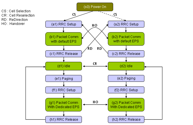
Figure 1. IntraRAT mobility between two LTE cells. The label on the arrow decides how much of the connection survives the move. Handover keeps it, redirection releases it and rebuilds it, and reselection runs only when there is no connection to keep.
- Cell Selection runs from (s0) Power On into (a1) RRC Setup or into (a2) RRC Setup. The UE takes one of the two, because at power on it has no cell yet and has to choose one.
- HO is the curved arrow with an arrowhead at each end, and it joins (b1) and (b2) Packet Comm. The connection survives the move, so the UE never visits RRC Setup or RRC Release on the way across.
- RD is the pair of straight diagonals that cross in the middle. One runs from (c1) RRC Release to (a2) RRC Setup, and the other runs from (c2) RRC Release to (a1) RRC Setup. The source cell releases the connection first, and the UE then builds a new one in the target cell.
- CR joins (d1) Idle and (d2) Idle, and it appears nowhere else on the diagram. Cell Reselection is an idle mode mechanism, and the drawing shows that by giving it a single arrow at the Idle level.
- The lower half repeats the upper half for a call the network starts: (d1) Idle, (e1) Paging, (f1) RRC Setup, (g1) Packet Comm With Dedicated EPS, then (h1) RRC Release. HO joins (g1) and (g2) there too, so handover behaves the same way once a dedicated bearer is up.
- (h1) and (h2) RRC Release return to (d1) and (d2) Idle along the outer edges. Each cell returns to its own Idle box, which makes the diagram a loop rather than a path.
More complicated (probably the most complicated) cases are the multi cell scenario among different technologies (different RATs). The big/high level picture would be as follows.
Figure 2 widens the same idea to three radio technologies. GSM/GPRS sits on the left in dark green, WCDMA sits on the right in light blue, and LTE occupies the middle in yellow-green with two cells rather than one. The dashed vertical lines mark the RAT boundaries. Every column carries Idle at the bottom and Packet Comm above it. The GSM and WCDMA columns carry a third box, Voice Comm, that neither LTE column has. That missing box is the reason CSFB exists, and the legend at the bottom adds CSFB to the four labels you already read in Figure 1.
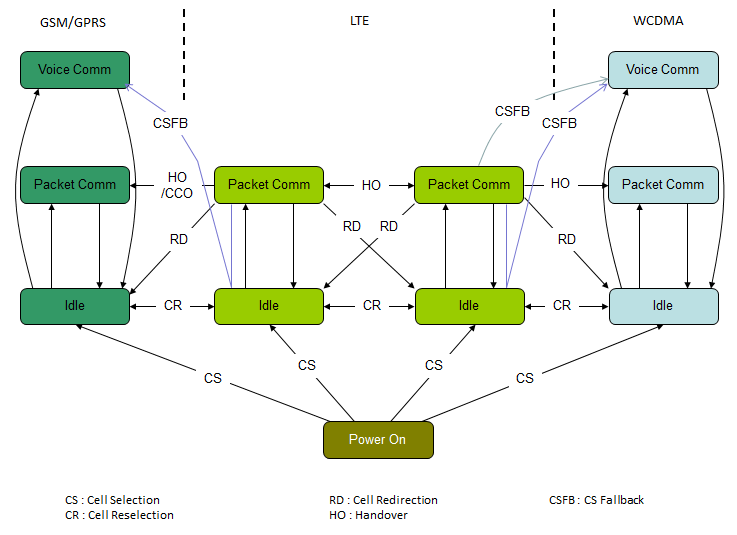
Figure 2. InterRAT mobility across GSM/GPRS, LTE and WCDMA. A horizontal arrow keeps the UE at the same level of activity. A diagonal arrow changes that level, and redirection and CS fallback are both drawn diagonally.
- Cell Selection runs from Power On at the bottom into each of the four Idle boxes. Figure 2 carries no RRC Setup box at all, because it is coarser than Figure 1 on purpose and drops the RRC procedures so that three RATs fit. So the arrow lands on Idle rather than on a procedure.
- CR joins neighbouring Idle boxes in one chain that runs from GSM Idle to WCDMA Idle through both LTE Idle boxes. So reselection crosses a RAT boundary in the same way it crosses a cell boundary.
- HO joins neighbouring Packet Comm boxes, and the two LTE cells carry an arrow in each direction. The arrow between GSM/GPRS and LTE carries the extra label CCO, because that move can also be done as a Cell Change Order instead of a handover.
- Every RD arrow starts at an LTE Packet Comm box and lands on an Idle box in a neighbouring column. Three targets appear: GSM Idle, the other LTE Idle, and WCDMA Idle. Figure 2 draws redirection out of LTE only.
- The coloured arrows are CSFB, and they are the only arrows that reach a Voice Comm box from outside its own column. They leave LTE and land on Voice Comm in GSM/GPRS and in WCDMA. LTE carries no Voice Comm state, so a circuit switched call has to be served somewhere else.
- GSM/GPRS and WCDMA each carry outer curves that join Idle and Voice Comm in both directions, and straight arrows that join Idle and Packet Comm. Those are ordinary state changes inside one RAT, so they carry no label.
The label on the arrow tells you what happens to the connection : HO keeps it, RD releases it and rebuilds it in the target cell, and CR runs only when there is no connection to keep.The activity level of the UE decides which mechanisms are even available : an idle UE can reselect, and a connected UE can be handed over or redirected. Reading the level first narrows the list before you look at anything else.LTE has no Voice Comm state : Figure 2 draws Voice Comm in GSM/GPRS and in WCDMA only. CSFB is the arrow that carries an LTE UE to one of them for a circuit switched call.Both diagrams are loops rather than paths : every branch returns to Idle, so you can reach any state again without a power cycle.
What do CS, CR, RD, HO and CSFB actually mean?
Figure 1 and Figure 2 use five two-letter labels, and the legends expand them into names rather than into explanations. The names are close to each other, which is what makes them easy to confuse. Cell Selection and Cell Reselection differ by one word. Redirection and handover both move the UE to another cell. So let’s separate them by the two questions that matter when you read a log: what state is the UE in when the mechanism starts, and who makes the decision?
Label |
UE state at the start |
Who decides |
What happens to the connection |
CS : Cell Selection |
No cell yet, just after power on or after losing coverage |
UE |
The UE has no connection yet. It finds a suitable cell, camps on it, and can then set a connection up. |
CR : Cell Reselection |
Idle |
UE |
The UE has no connection to hand over. It camps on a different cell and stays idle. |
RD : Cell Redirection |
Connected |
Network |
The network releases the connection and names the carrier to go to. The UE then sets up a new connection in the target cell. |
HO : Handover |
Connected |
Network |
The UE keeps the connection. It moves to the target cell without releasing it first. |
CSFB : CS Fallback |
Idle or connected on LTE, with a circuit switched call to make or answer |
UE or network, depending on which side placed the call |
The UE leaves LTE for a RAT that has a circuit switched domain, and it takes the call there. |
Two of the five cause most of the field trouble, and they are the two the network decides: handover and redirection. Both of them start from a measurement report that the UE sends, so a measurement configuration error often appears as a handover failure. The Measurement in LTE page linked from this page covers what the UE is told to measure and when it has to report.
Cell Selection and Cell Reselection are the UE’s own decisions, and the network only influences them through the parameters it broadcasts in system information. So check the broadcast parameters first when a UE camps on a cell you did not expect. A signalling trace will not show you the decision, because the UE sends nothing at the moment it reselects. A tracking area update may follow, but only when the new cell belongs to a different tracking area.
The UE decides CS and CR, and the network decides RD and HO : so look at the broadcast parameters for a reselection problem, and at the measurement configuration and the eNB for a handover problem.Only handover keeps the connection : redirection looks similar on a state diagram, but the UE releases and re-establishes, and the user sees that as a gap.CSFB exists because LTE carries no circuit switched domain : the UE has to move to GSM/GPRS or WCDMA for the call, which is why the CSFB arrows always cross a RAT boundary.A handover problem is often a measurement problem : the eNB can only act on what the UE reports, so check the reporting configuration before you suspect the handover procedure itself.