|
WiFi |
||
|
RF Test
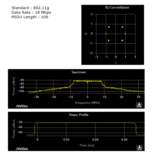
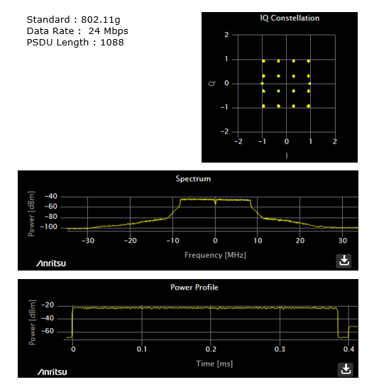
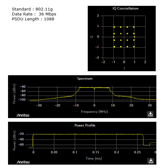
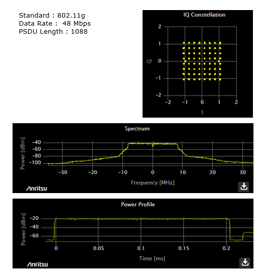
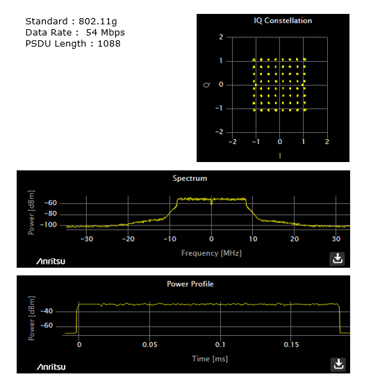
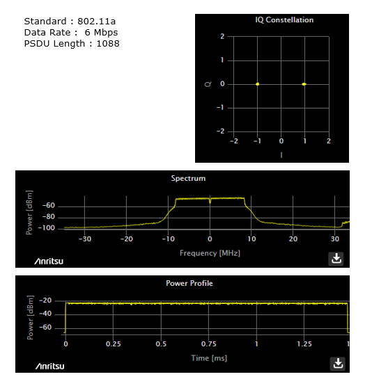
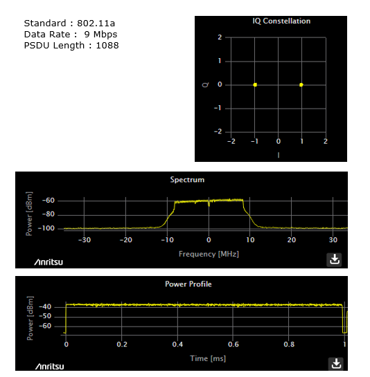
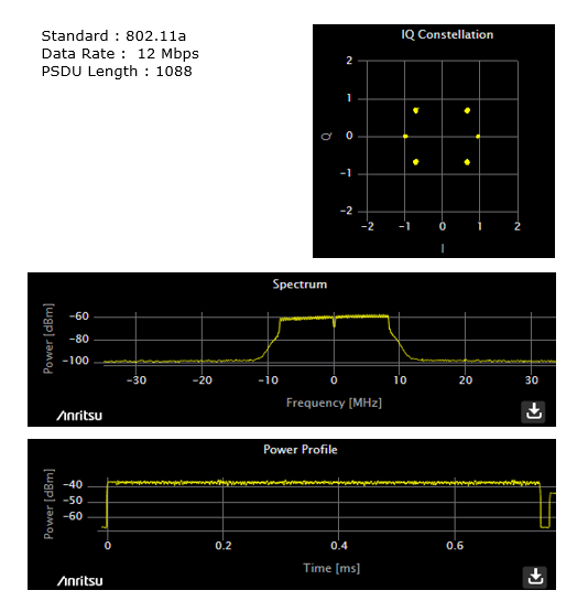
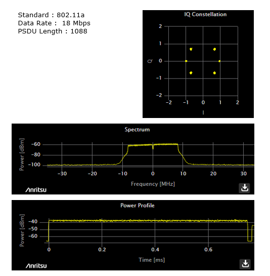
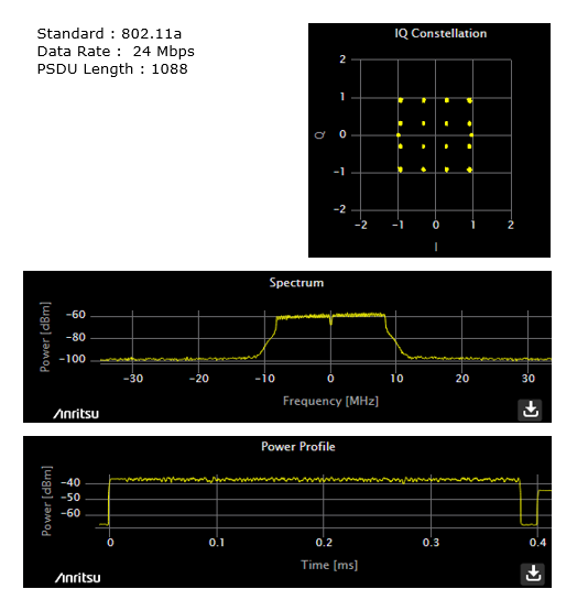
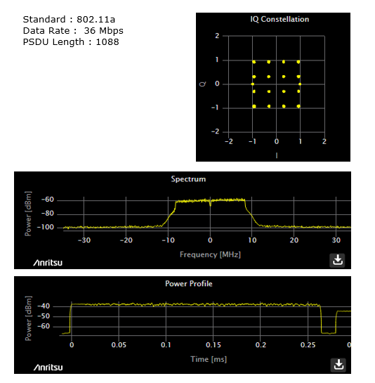
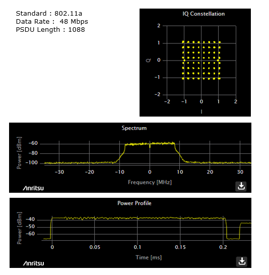
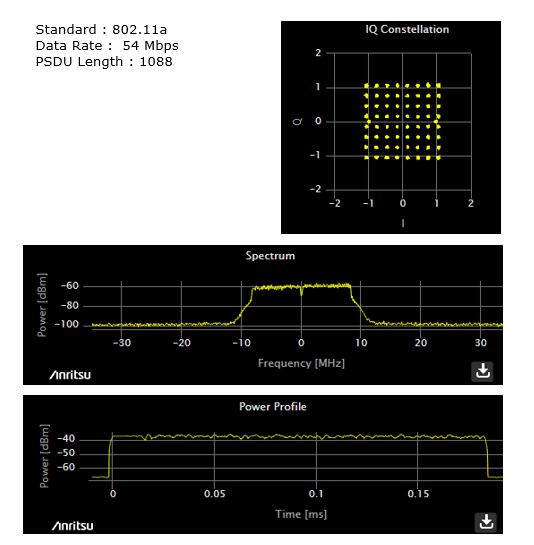
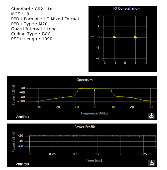
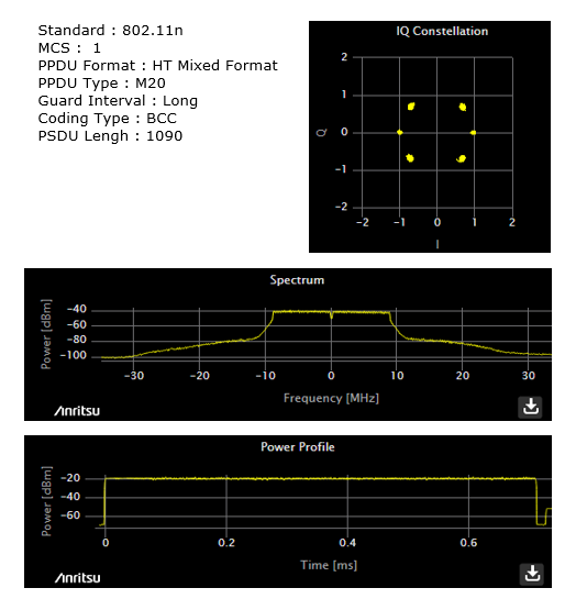
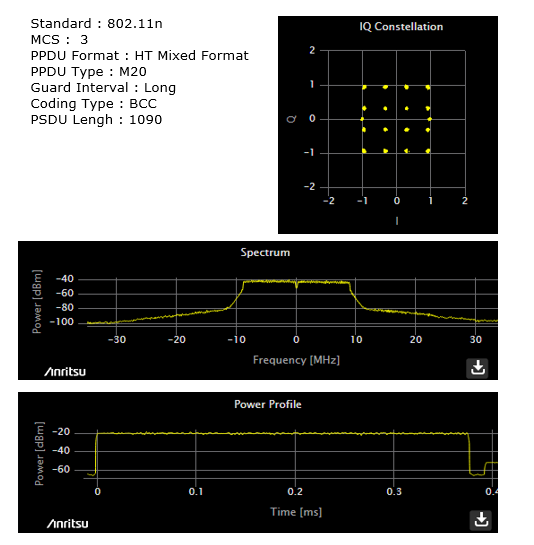
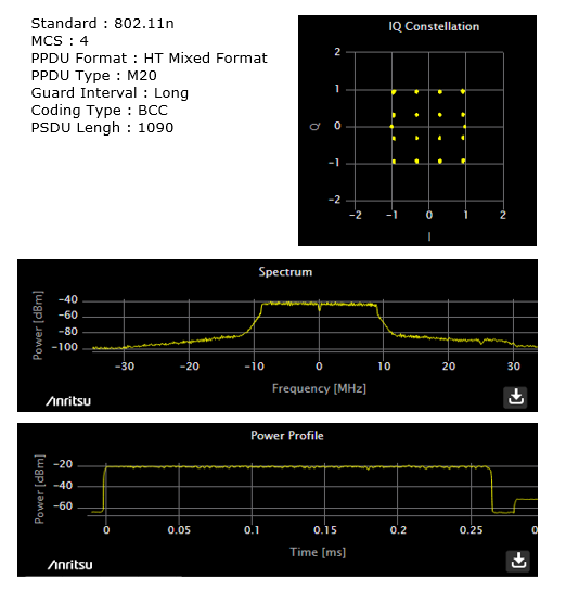
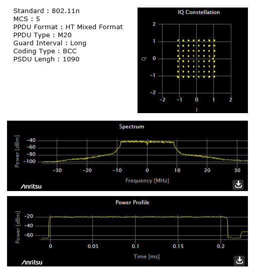
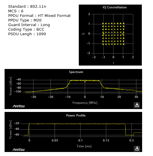
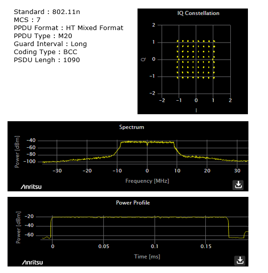
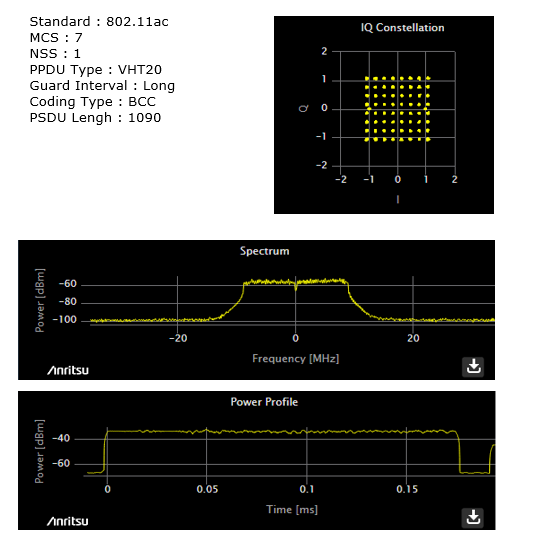
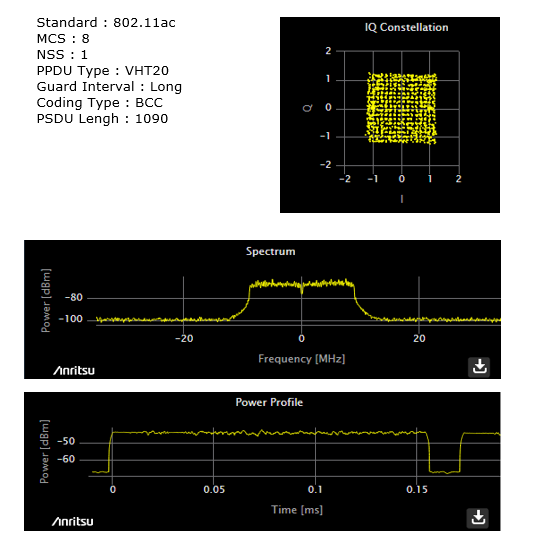
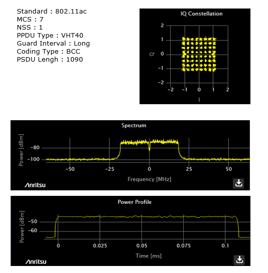
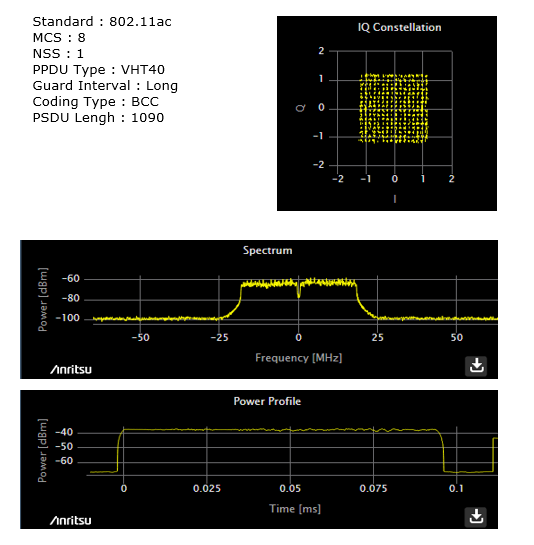
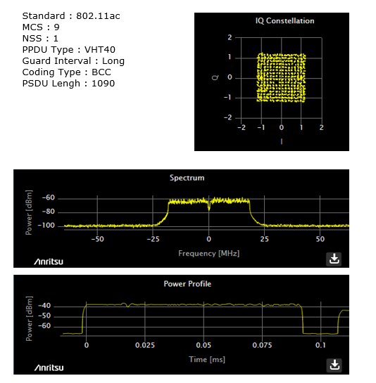
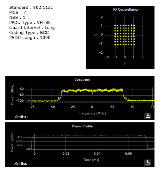
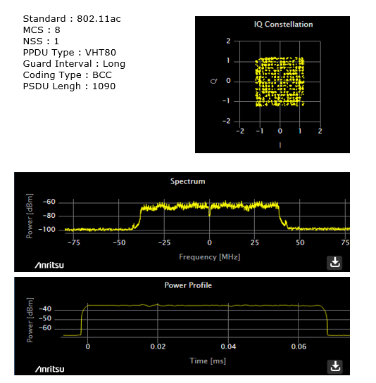
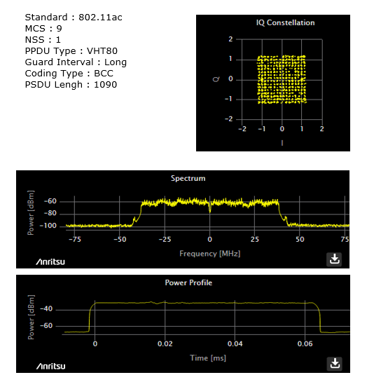
You will find over 20 formal test cases based on IEEE 802.11 series, but I would not explain much details of each test cases. What I intend to do in this page is to give you snapshots for the most basic test that can be represented in graph to give some intuitive understandings of WLAN signal. At first, most of the plot would look similar but you would see the differences. Try to take go through each of these plots 10 times including the numbers in each axis and see if you find (at least feel) anything different with every look.
General Principle of RF Measurement
For a wireless communication device to work properly, it should meet following hardware requirement
i) The device should transmit the signal with strong enough power to make it sure it reaches the other party of the communication. ii) The device should not transmit the signal with so strong power that it interfere the communication between other parties. iii) The device should transmit the signal with good enough quality which can be decoded/corrected by the other party. iv) The device should transmit the signal in the exact frequency that has been allocated for the communication. v) The device should not generate any noise out side of the frequency area that has been allocated for the device.
If any of these condition deviate too much from the specification, the device cannot communicate with the other party or prevent(interfer) some other device from communicating with their partner. In terms of measurement equipment, item i) and ii) belong to "power measurement", item iii) is related to "Modulation Analysis" and item iv) falls into "Frequency Error measurement". Item v) is also a kind of "power measurement", but the measurement area in frequency domain is different from item i) & item ii). Anyway if you have any equipment that can perform the following three measurement for your communication technology, you can do the most critical part of transmission path. a) Power Measurement (spectrum measurement) b) Modulation Analysis c) Frequency Error Measurement If you have any general purpose spectrum analyzer with enough bandwidth and frequency, you may do most of power measuremennt for any wireless devices. However, for Modulation Analyzer and Frequency Error Measurement you would need a specific measurement equipment designed for a specific wireless technlogy.
Now let's think about the recieve path measurement. What would be the most important reciever characteristics for the communication device ?
i) The reciever must be able to decode successfuly the signal coming from a transmitter even though the signal strength is very low. ii) The reciever must be able to decode successfuly the signal coming from a transmitter even when there are a certain level of noise around the signal.
In terms of measurement logic, item i) and ii) are the same. In some wireless technlogy (e.g, CDMA, WCDMA etc) Equipment sends a pattern of the known signal and let the reciever decode it and compare the original signal from the equipment and the decoded signal by reciever and how much different they are. The more different they are, the poorer reciever quality it is. We call this method "BER(Bit Error Rate) measurement". Item i) measures BER when the input signal to the device is very low and Item ii) measures BER when there are noise to the input signal. In some other technology(e.g, LTE, WiFi, Bluetooth etc), equipment does not compare the TX and RX data bit by bit. They just send a packet and checks the response from the DUT. If DUT successfully decoded the packet, it would send 'ACK' and if it fails to decode the packet, it would send 'NACK' . Since DUT make this kind of judgement based on decoding a while frame, this kind of test is called FER(Frame Error Rate) test or PER(Packet Error Rate) test.
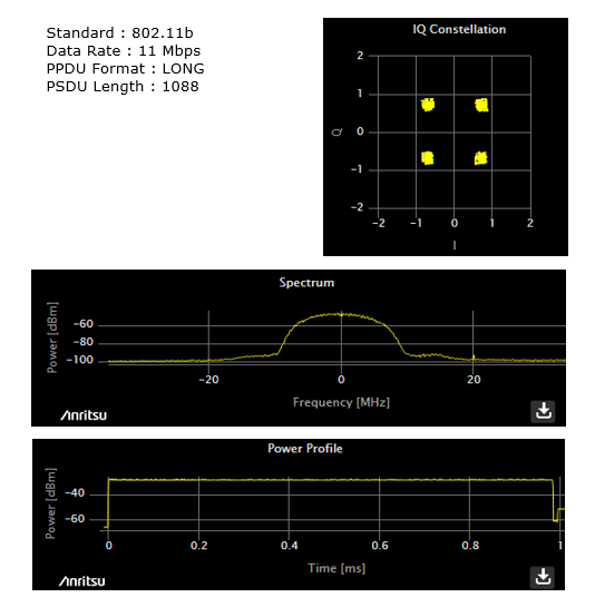
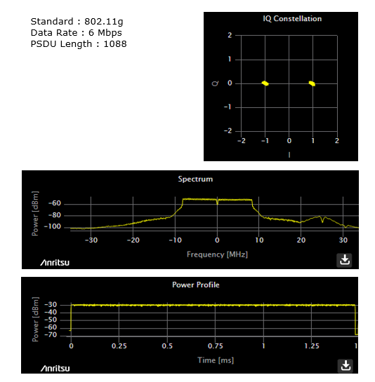
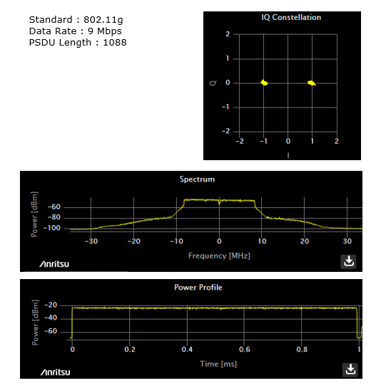
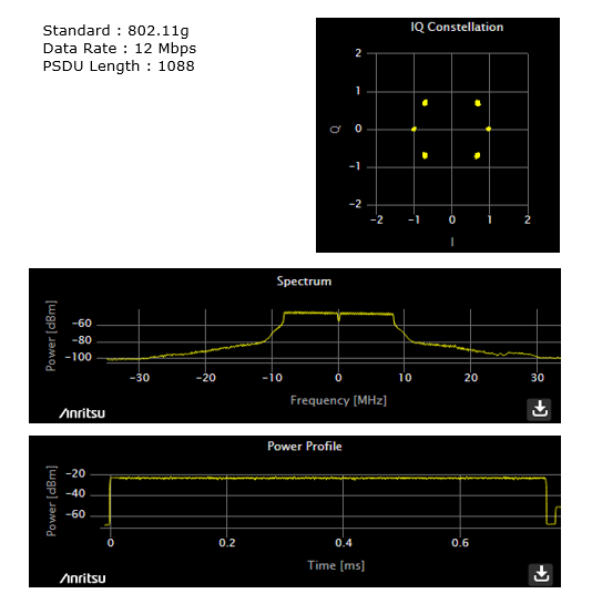
Measurement Example of RF TX
I captured all of these plots , Anritsu MT8862. You can see the test setup on how these are tested (For 802.11a,b,g I used SamSung GS4 as a DUT and for 802.11ac I used a WiFi dongle from D-Link as a DUT). The measurement result shown here is not from the strictly controlled measurement. So don't expect these result to be in PASS range by the specification. These are put here just to give you some idea of how some of the fundamental RF signal property of various WLAN signal look like.
|
||