Matlab Toolbox - 4G/LTE
PDCCH
If you don't know what PBCH(Physical BroadCasting Channel) is, refer to Physical Layer Channel : Downlink : PDCCH (Physical Download Control Channel) page first.
< DCI Message Bit Generation >
First step for creating PDCCH is to generate bit stream (informations) to be carried by PDCCH. As you know, PDCCH is the channel carrying the DCI information. So the first step is basically defining a specific DCI informations.
% First you have to define properites of a eNodeB.
% NDLRB indicate System Bandwith in the unit of RBs.
% NDLRB 6 = 1.4 Mhz, NDLRB 15 = 3.0 Mhz, NDLRB 25 = 5.0 Mhz,
% NDLRB 50 = 10 Mhz, NDLRB 75 = 15 Mhz, NDLRB 100 = 20 Mhz
% CellRefP indicate number of downlink Antenna. CellRefP = 1 means 1 transmission antenna (SISO)
% NCellID indicate PCI (Physical Channel Identity) of the Cell
% NSubframe indicate the subframe number.
enb.CyclicPrefix = 'Normal';
enb.PHICHDuration = 'Normal';
enb.Ng = 'Sixth';
enb.NDLRB = 6;
enb.CellRefP = 1;
enb.DuplexMode = 'FDD';
enb.NCellID = 0;
enb.NSubframe = 0;
enb.CFI = 3;
% Now populate all the information in DCI field as you like. Understanding details of DCI is also pretty huge topics.
% You would need separate page for DCI for the details.
dci.NDLRB = enb.NDLRB;
dci.DCIFormat = 'Format1A';
dci.AllocationType = 0;
dci.Allocation.RIV = 18;
dci.ModCoding = 10;
dci.HARQNo = 0;
dci.NewData = 0;
dci.TPCPUCCH = 0;
dci.DuplexMode = 'FDD';
dci.NTxAnts = 1;
% once you defined all the detailed fields of DCI, just pass it to lteDCI() function with eNB info as follows,
% then you will get the bit stream for the DCI.
[dciMessage,dciMessageBits] = lteDCI(enb,dci);
% Following shows one example the DCI bits generated by lteDCI(). This bit stream is the input to the step (1)
% of the procedure described in Physical Layer Channel : Downlink : PDCCH (Physical Download Control Channel)
|
dci.NDLRB = enb.NDLRB; dci.DCIFormat = 'Format1A'; dci.AllocationType = 0; dci.Allocation.RIV = 18; dci.ModCoding = 10; dci.HARQNo = 0; dci.NewData = 0; dci.TPCPUCCH = 0; dci.DuplexMode = 'FDD'; dci.NTxAnts = 1; |
|
|
dciMessageBits(21 bits) = 1 0 1 0 0 1 0 0 1 0 1 0 0 0 0 0 0 0 0 0 0 |
|
< DCI Channel Coding >
This section will show the result of steps (1)~(3) described in Physical Layer Channel : Downlink : PDCCH (Physical Download Control Channel).
% First you have to define properites of a eNodeB.
% NDLRB indicate System Bandwith in the unit of RBs.
% NDLRB 6 = 1.4 Mhz, NDLRB 15 = 3.0 Mhz, NDLRB 25 = 5.0 Mhz,
% NDLRB 50 = 10 Mhz, NDLRB 75 = 15 Mhz, NDLRB 100 = 20 Mhz
% CellRefP indicate number of downlink Antenna. CellRefP = 1 means 1 transmission antenna (SISO)
% NCellID indicate PCI (Physical Channel Identity) of the Cell
% NSubframe indicate the subframe number.
enb.CyclicPrefix = 'Normal';
enb.PHICHDuration = 'Normal';
enb.Ng = 'Sixth';
enb.NDLRB = 6;
enb.CellRefP = 1;
enb.DuplexMode = 'FDD';
enb.NCellID = 0;
enb.NSubframe = 0;
enb.CFI = 3;
% Now populate all the information in DCI field as you like. Understanding details of DCI is also pretty huge topics.
% You would need separate page for DCI for the details.
dci.NDLRB = enb.NDLRB;
dci.DCIFormat = 'Format1A';
dci.AllocationType = 0;
dci.Allocation.RIV = 18;
dci.ModCoding = 10;
dci.HARQNo = 0;
dci.NewData = 0;
dci.TPCPUCCH = 0;
dci.DuplexMode = 'FDD';
dci.NTxAnts = 1;
% once you defined all the detailed fields of DCI, just pass it to lteDCI() function with eNB info as follows,
% then you will get the bit stream for the DCI.
[dciMessage,dciMessageBits] = lteDCI(enb,dci);
% for this step, you need to set a couple of additional parameters as shown below. C_RNTI will be XORed to CRC bits
% PDCCHFormat will determined Aggregation Level.
% PDCCHFormat 0 indicate Aggregation Level 1
% PDCCHFormat 1 indicate Aggregation Level 2
% PDCCHFormat 2 indicate Aggregation Level 4
% PDCCHFormat 3 indicate Aggregation Level 8
C_RNTI = 100;
pdcchConfig.RNTI = C_RNTI;
pdcchConfig.PDCCHFormat = 0;
% then pass dciMessageBits and pdcchConfig to lteDCIEncode, the you would get the encoded bitstream.
codedDciBits = lteDCIEncode(pdcchConfig, dciMessageBits);
% Following is one example of channel coding for DCI.
|
dci.NDLRB = enb.NDLRB; dci.DCIFormat = 'Format1A'; dci.AllocationType = 0; dci.Allocation.RIV = 18; dci.ModCoding = 10; dci.HARQNo = 0; dci.NewData = 0; dci.TPCPUCCH = 0; dci.DuplexMode = 'FDD'; dci.NTxAnts = 1;
C_RNTI = 100; pdcchConfig.RNTI = C_RNTI; pdcchConfig.PDCCHFormat = 0; |
|
|
codedDciBits (72 bits) = 1 1 1 0 1 0 0 1 1 1 1 1 0 1 1 1 0 1 1 1 0 0 0 0 0 0 1 1 0 0 1 0 0 1 0 1 1 0 1 1 0 0 1 0 1 1 1 1 1 0 1 1 0 0 1 0 0 0 1 1 1 0 0 1 0 1 1 0 1 1 0 0 |
|
|
dci.NDLRB = enb.NDLRB; dci.DCIFormat = 'Format1A'; dci.AllocationType = 0; dci.Allocation.RIV = 18; dci.ModCoding = 10; dci.HARQNo = 0; dci.NewData = 0; dci.TPCPUCCH = 0; dci.DuplexMode = 'FDD'; dci.NTxAnts = 1;
C_RNTI = 100; pdcchConfig.RNTI = C_RNTI; pdcchConfig.PDCCHFormat = 1; |
|
|
codedDciBits (144 bits) = 1 1 1 0 1 0 0 1 1 1 1 1 0 1 1 1 0 1 1 1 0 0 0 0 0 0 1 1 0 0 1 0 0 1 0 1 1 0 1 1 0 0 1 0 1 1 1 1 1 0 1 1 0 0 1 0 0 0 1 1 1 0 0 1 0 1 1 0 1 1 0 0 0 0 1 1 0 1 0 0 0 1 1 0 1 1 1 1 0 1 0 0 1 1 0 0 0 0 1 0 1 0 1 1 0 1 0 0 0 1 1 1 1 1 0 1 0 0 1 1 1 1 1 0 1 1 1 0 1 1 1 0 0 0 0 0 0 1 1 0 0 1 0 0 |
|
|
dci.NDLRB = enb.NDLRB; dci.DCIFormat = 'Format1A'; dci.AllocationType = 0; dci.Allocation.RIV = 18; dci.ModCoding = 10; dci.HARQNo = 0; dci.NewData = 0; dci.TPCPUCCH = 0; dci.DuplexMode = 'FDD'; dci.NTxAnts = 1;
C_RNTI = 100; pdcchConfig.RNTI = C_RNTI; pdcchConfig.PDCCHFormat = 2; |
|
|
codedDciBits (288 bits) = 1 1 1 0 1 0 0 1 1 1 1 1 0 1 1 1 0 1 1 1 0 0 0 0 0 0 1 1 0 0 1 0 0 1 0 1 1 0 1 1 0 0 1 0 1 1 1 1 1 0 1 1 0 0 1 0 0 0 1 1 1 0 0 1 0 1 1 0 1 1 0 0 0 0 1 1 0 1 0 0 0 1 1 0 1 1 1 1 0 1 0 0 1 1 0 0 0 0 1 0 1 0 1 1 0 1 0 0 0 1 1 1 1 1 0 1 0 0 1 1 1 1 1 0 1 1 1 0 1 1 1 0 0 0 0 0 0 1 1 0 0 1 0 0 1 0 1 1 0 1 1 0 0 1 0 1 1 1 1 1 0 1 1 0 0 1 0 0 0 1 1 1 0 0 1 0 1 1 0 1 1 0 0 0 0 1 1 0 1 0 0 0 1 1 0 1 1 1 1 0 1 0 0 1 1 0 0 0 0 1 0 1 0 1 1 0 1 0 0 0 1 1 1 1 1 0 1 0 0 1 1 1 1 1 0 1 1 1 0 1 1 1 0 0 0 0 0 0 1 1 0 0 1 0 0 1 0 1 1 0 1 1 0 0 1 0 1 1 1 1 1 0 1 1 0 0 1 0 0 0 1 1 1 0 0 1 0 1 |
|
|
dci.NDLRB = enb.NDLRB; dci.DCIFormat = 'Format1A'; dci.AllocationType = 0; dci.Allocation.RIV = 18; dci.ModCoding = 10; dci.HARQNo = 0; dci.NewData = 0; dci.TPCPUCCH = 0; dci.DuplexMode = 'FDD'; dci.NTxAnts = 1;
C_RNTI = 100; pdcchConfig.RNTI = C_RNTI; pdcchConfig.PDCCHFormat = 3; |
|
|
codedDciBits (576 bits) = 1 1 1 0 1 0 0 1 1 1 1 1 0 1 1 1 0 1 1 1 0 0 0 0 0 0 1 1 0 0 1 0 0 1 0 1 1 0 1 1 0 0 1 0 1 1 1 1 1 0 1 1 0 0 1 0 0 0 1 1 1 0 0 1 0 1 1 0 1 1 0 0 0 0 1 1 0 1 0 0 0 1 1 0 1 1 1 1 0 1 0 0 1 1 0 0 0 0 1 0 1 0 1 1 0 1 0 0 0 1 1 1 1 1 0 1 0 0 1 1 1 1 1 0 1 1 1 0 1 1 1 0 0 0 0 0 0 1 1 0 0 1 0 0 1 0 1 1 0 1 1 0 0 1 0 1 1 1 1 1 0 1 1 0 0 1 0 0 0 1 1 1 0 0 1 0 1 1 0 1 1 0 0 0 0 1 1 0 1 0 0 0 1 1 0 1 1 1 1 0 1 0 0 1 1 0 0 0 0 1 0 1 0 1 1 0 1 0 0 0 1 1 1 1 1 0 1 0 0 1 1 1 1 1 0 1 1 1 0 1 1 1 0 0 0 0 0 0 1 1 0 0 1 0 0 1 0 1 1 0 1 1 0 0 1 0 1 1 1 1 1 0 1 1 0 0 1 0 0 0 1 1 1 0 0 1 0 1 1 0 1 1 0 0 0 0 1 1 0 1 0 0 0 1 1 0 1 1 1 1 0 1 0 0 1 1 0 0 0 0 1 0 1 0 1 1 0 1 0 0 0 1 1 1 1 1 0 1 0 0 1 1 1 1 1 0 1 1 1 0 1 1 1 0 0 0 0 0 0 1 1 0 0 1 0 0 1 0 1 1 0 1 1 0 0 1 0 1 1 1 1 1 0 1 1 0 0 1 0 0 0 1 1 1 0 0 1 0 1 1 0 1 1 0 0 0 0 1 1 0 1 0 0 0 1 1 0 1 1 1 1 0 1 0 0 1 1 0 0 0 0 1 0 1 0 1 1 0 1 0 0 0 1 1 1 1 1 0 1 0 0 1 1 1 1 1 0 1 1 1 0 1 1 1 0 0 0 0 0 0 1 1 0 0 1 0 0 1 0 1 1 0 1 1 0 0 1 0 1 1 1 1 1 0 1 1 0 0 1 0 0 0 1 1 1 0 0 1 0 1 1 0 1 1 0 0 0 0 1 1 0 1 0 0 0 1 1 0 1 1 1 1 0 1 0 0 1 1 0 0 0 0 1 0 1 0 1 1 0 1 0 0 0 1 1 1 1 1 0 1 0 0 1 1 1 1 1 0 1 1 1 0 1 1 1 0 |
|
< Calculation of Available Resources >
This section shows how to figure out the amount of resources that can be allocated for PDCCH transmission. The amount of the resources for PDCCH is determined mainly by System Bandwidth and CFI which are the attribute of eNB.
% First you have to define properites of a eNodeB.
% NDLRB indicate System Bandwith in the unit of RBs.
% NDLRB 6 = 1.4 Mhz, NDLRB 15 = 3.0 Mhz, NDLRB 25 = 5.0 Mhz,
% NDLRB 50 = 10 Mhz, NDLRB 75 = 15 Mhz, NDLRB 100 = 20 Mhz
% CellRefP indicate number of downlink Antenna. CellRefP = 1 means 1 transmission antenna (SISO)
% NCellID indicate PCI (Physical Channel Identity) of the Cell
% NSubframe indicate the subframe number.
enb.CyclicPrefix = 'Normal';
enb.PHICHDuration = 'Normal';
enb.Ng = 'Sixth';
enb.NDLRB = 6;
enb.CellRefP = 1;
enb.DuplexMode = 'FDD';
enb.NCellID = 0;
enb.NSubframe = 0;
enb.CFI = 3;
% If you pass the enb into ltePDCCHInfo() function, it will give you the amount of resources that can be allocated
% for PDCCH allocation. This is not the amount of resource for only one DCI. It will give you the total/maximum
% amount of the resources that can be allocated for PDCCH.
pdcchDims = ltePDCCHInfo(enb);
|
C_RNTI = 100; pdcchConfig.RNTI = C_RNTI; pdcchConfig.PDCCHFormat = 0; |
|
|
pdcchDims = NREG: 59 NRE: 236 NCCE: 6 NREGUsed: 54 NREUsed: 216 MTot: 472 NSymbols: 4 |
|
< Locate PDCCH Candidates >
This section would show PDCCH Candidate. This is not specific to each DCI, it is about the all the possible spaces that can carry on PDCCH, so you don't need to specify any specific DCI at this step.
% First you have to define properites of a eNodeB.
% NDLRB indicate System Bandwith in the unit of RBs.
% NDLRB 6 = 1.4 Mhz, NDLRB 15 = 3.0 Mhz, NDLRB 25 = 5.0 Mhz,
% NDLRB 50 = 10 Mhz, NDLRB 75 = 15 Mhz, NDLRB 100 = 20 Mhz
% CellRefP indicate number of downlink Antenna. CellRefP = 1 means 1 transmission antenna (SISO)
% NCellID indicate PCI (Physical Channel Identity) of the Cell
% NSubframe indicate the subframe number.
enb.CyclicPrefix = 'Normal';
enb.PHICHDuration = 'Normal';
enb.Ng = 'Sixth';
enb.NDLRB = 6;
enb.CellRefP = 1;
enb.DuplexMode = 'FDD';
enb.NCellID = 0;
enb.NSubframe = 0;
enb.CFI = 3;
% for this step, you need to set a couple of additional parameters as shown below. C_RNTI will be XORed to CRC bits
% PDCCHFormat will determined Aggregation Level.
% PDCCHFormat 0 indicate Aggregation Level 1
% PDCCHFormat 1 indicate Aggregation Level 2
% PDCCHFormat 2 indicate Aggregation Level 4
% PDCCHFormat 3 indicate Aggregation Level 8
C_RNTI = 100;
pdcchConfig.RNTI = C_RNTI;
pdcchConfig.PDCCHFormat = 0;
% If you pass the enb into ltePDCCHInfo() function, it will give you the amount of resources that can be allocated
% for PDCCH allocation. This is not the amount of resource for only one DCI. It will give you the total/maximum
% amount of the resources that can be allocated for PDCCH.
% the output of ltePDCCHInfo() will be used ltePDCCHSpace() in next step to calculate PDCCH Space.
pdcchDims = ltePDCCHInfo(enb);
% With ltePDCCHSpace, you can get the list of all the possible spaces that can carry PDCCH. In this example,
% the space were shown in the unit of bits.
pdcchBits = -1*ones(pdcchDims.MTot, 1);
candidates = ltePDCCHSpace(enb, pdcchConfig, {'bits', '1based'});
% Followings are not required information in this post, but I put this as a additional reference for your study.
% If you want to calculate the PDCCH space manually to understand details of 3GPP specification.
% this can be a good information to verify your own calculation.
candidatesRE = ltePDCCHSpace(enb, pdcchConfig, {'re', '1based'});
candidatesREG = ltePDCCHSpace(enb, pdcchConfig, {'reg', '1based'});
|
enb.NDLRB = 6; enb.CFI = 3;
C_RNTI = 100; pdcchConfig.RNTI = C_RNTI; pdcchConfig.PDCCHFormat = 0; |
|
|
candidates = 145 216 ==> 72 bits 217 288 ==> 72 bits 289 360 ==> 72 bits 361 432 ==> 72 bits 1 72 ==> 72 bits 73 144 ==> 72 bits
candidatesRE = 73 108 ==> 36 REs 109 144 ==> 36 REs 145 180 ==> 36 REs 181 216 ==> 36 REs 1 36 ==> 36 REs 37 72 ==> 36 REs
candidatesREG = 19 27 ==> 9 REG 28 36 ==> 9 REG 37 45 ==> 9 REG 46 54 ==> 9 REG 1 9 ==> 9 REG 10 18 ==> 9 REG |
|
|
enb.NDLRB = 6; enb.CFI = 3;
C_RNTI = 100; pdcchConfig.RNTI = C_RNTI; pdcchConfig.PDCCHFormat = 1; |
|
|
candidates = 289 432 ==> 144 bits 1 144 ==> 144 bits 145 288 ==> 144 bits 289 432 ==> 144 bits 1 144 ==> 144 bits 145 288 ==> 144 bits
candidatesRE = 145 216 ==> 72 RE 1 72 ==> 72 RE 73 144 ==> 72 RE 145 216 ==> 72 RE 1 72 ==> 72 RE 73 144 ==> 72 RE
candidatesREG = 37 54 ==> 18 REG 1 18 ==> 18 REG 19 36 ==> 18 REG 37 54 ==> 18 REG 1 18 ==> 18 REG 19 36 ==> 18 REG |
|
|
enb.NDLRB = 6; enb.CFI = 3;
C_RNTI = 100; pdcchConfig.RNTI = C_RNTI; pdcchConfig.PDCCHFormat = 2; |
|
|
candidates = 1 288 ==> 288 bits 1 288 ==> 288 bits
candidatesRE = 1 144 ==> 144 RE 1 144 ==> 144 RE
candidatesREG = 1 36 ==> 36 REG 1 36 ==> 36 REG |
|
|
enb.NDLRB = 6; enb.CFI = 3;
C_RNTI = 100; pdcchConfig.RNTI = C_RNTI; pdcchConfig.PDCCHFormat = 3; |
|
|
candidates = Not Applicable
candidatesRE = Not Applicable
candidatesREG = Not Applicable |
|
< Allocate the codedBits to one of the Candidates >
In this section, I would create a long bit string that can contain all the possible PDCCH and then allocated the PDCCH codeBits to one of the candidate area.
% First you have to define properites of a eNodeB.
% NDLRB indicate System Bandwith in the unit of RBs.
% NDLRB 6 = 1.4 Mhz, NDLRB 15 = 3.0 Mhz, NDLRB 25 = 5.0 Mhz,
% NDLRB 50 = 10 Mhz, NDLRB 75 = 15 Mhz, NDLRB 100 = 20 Mhz
% CellRefP indicate number of downlink Antenna. CellRefP = 1 means 1 transmission antenna (SISO)
% NCellID indicate PCI (Physical Channel Identity) of the Cell
% NSubframe indicate the subframe number.
enb.CyclicPrefix = 'Normal';
enb.PHICHDuration = 'Normal';
enb.Ng = 'Sixth';
enb.NDLRB = 6;
enb.CellRefP = 1;
enb.DuplexMode = 'FDD';
enb.NCellID = 0;
enb.NSubframe = 0;
enb.CFI = 3;
% Now populate all the information in DCI field as you like. Understanding details of DCI is also pretty huge topics.
% You would need separate page for DCI for the details.
dci.NDLRB = enb.NDLRB;
dci.DCIFormat = 'Format1A';
dci.AllocationType = 0;
dci.Allocation.RIV = 18;
dci.ModCoding = 10;
dci.HARQNo = 0;
dci.NewData = 0;
dci.TPCPUCCH = 0;
dci.DuplexMode = 'FDD';
dci.NTxAnts = 1;
% once you defined all the detailed fields of DCI, just pass it to lteDCI() function with eNB info as follows,
% then you will get the bit stream for the DCI.
[dciMessage,dciMessageBits] = lteDCI(enb,dci);
% for this step, you need to set a couple of additional parameters as shown below. C_RNTI will be XORed to CRC bits
% PDCCHFormat will determined Aggregation Level.
% PDCCHFormat 0 indicate Aggregation Level 1
% PDCCHFormat 1 indicate Aggregation Level 2
% PDCCHFormat 2 indicate Aggregation Level 4
% PDCCHFormat 3 indicate Aggregation Level 8
C_RNTI = 100;
pdcchConfig.RNTI = C_RNTI;
pdcchConfig.PDCCHFormat = 0;
% Then if you pass the dciMessageBits and pdcchConfig into lteDCIEncode(), it will generated codedDciBits.
codedDciBits = lteDCIEncode(pdcchConfig, dciMessageBits);
pdcchDims = ltePDCCHInfo(enb);
% generate an array with the length that can accommodate all the possible PDCCH bits.
pdcchBits = -1*ones(pdcchDims.MTot, 1);
% With ltePDCCHSpace, you can get the list of all the possible spaces that can carry PDCCH. In this example,
% the space were shown in the unit of bits.
candidates = ltePDCCHSpace(enb, pdcchConfig, {'bits', '1based'});
% select one of the candidate bitSection and assign the codedDcitBits. You can select any candidate bit section,
% but in this example, I selected the first candidate section.
pdcchBits ( candidates(1, 1) : candidates(1, 2) ) = codedDciBits;
< Generating PDCCH Symbols >
In this section, I will generate the modulated symbol (a bit string modulated by QPSK) for PDCCH.
% First you have to define properites of a eNodeB.
% NDLRB indicate System Bandwith in the unit of RBs.
% NDLRB 6 = 1.4 Mhz, NDLRB 15 = 3.0 Mhz, NDLRB 25 = 5.0 Mhz,
% NDLRB 50 = 10 Mhz, NDLRB 75 = 15 Mhz, NDLRB 100 = 20 Mhz
% CellRefP indicate number of downlink Antenna. CellRefP = 1 means 1 transmission antenna (SISO)
% NCellID indicate PCI (Physical Channel Identity) of the Cell
% NSubframe indicate the subframe number.
enb.CyclicPrefix = 'Normal';
enb.PHICHDuration = 'Normal';
enb.Ng = 'Sixth';
enb.NDLRB = 6;
enb.CellRefP = 1;
enb.DuplexMode = 'FDD';
enb.NCellID = 0;
enb.NSubframe = 0;
enb.CFI = 3;
% Now populate all the information in DCI field as you like. Understanding details of DCI is also pretty huge topics.
% You would need separate page for DCI for the details.
dci.NDLRB = enb.NDLRB;
dci.DCIFormat = 'Format1A';
dci.AllocationType = 0;
dci.Allocation.RIV = 18;
dci.ModCoding = 10;
dci.HARQNo = 0;
dci.NewData = 0;
dci.TPCPUCCH = 0;
dci.DuplexMode = 'FDD';
dci.NTxAnts = 1;
% once you defined all the detailed fields of DCI, just pass it to lteDCI() function with eNB info as follows,
% then you will get the bit stream for the DCI.
[dciMessage,dciMessageBits] = lteDCI(enb,dci);
% for this step, you need to set a couple of additional parameters as shown below. C_RNTI will be XORed to CRC bits
% PDCCHFormat will determined Aggregation Level.
% PDCCHFormat 0 indicate Aggregation Level 1
% PDCCHFormat 1 indicate Aggregation Level 2
% PDCCHFormat 2 indicate Aggregation Level 4
% PDCCHFormat 3 indicate Aggregation Level 8
C_RNTI = 100;
pdcchConfig.RNTI = C_RNTI;
pdcchConfig.PDCCHFormat = 0;
% Then if you pass the dciMessageBits and pdcchConfig into lteDCIEncode(), it will generated codedDciBits.
codedDciBits = lteDCIEncode(pdcchConfig, dciMessageBits);
pdcchDims = ltePDCCHInfo(enb);
% generate an array with the length that can accommodate all the possible PDCCH bits.
pdcchBits = -1*ones(pdcchDims.MTot, 1);
% With ltePDCCHSpace, you can get the list of all the possible spaces that can carry PDCCH. In this example,
% the space were shown in the unit of bits.
candidates = ltePDCCHSpace(enb, pdcchConfig, {'bits', '1based'});
% select one of the candidate bitSection and assign the codedDcitBits. You can select any candidate bit section,
% but in this example, I selected the first candidate section.
pdcchBits ( candidates(1, 1) : candidates(1, 2) ) = codedDciBits;
% if pass the encodedBits into ltePDCCH(), it will generate the modulated physical layer symbols.
pdcch_sym = ltePDCCH(enb, pdcchBits);
pdcch_sym_arrayIndex = 0:length(pdcch_sym)-1;
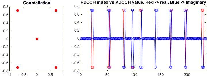
% Now I will plot the modulated symbol in two forms. Constellation in the left side and I/Q in bit sequence on the
% right side.
subplot(1,3,1);
plot(real(pdcch_sym),imag(pdcch_sym),'ro','MarkerFaceColor',[1 0 0]);
title('Constellation');
subplot(1,3,[2 3]);
plot(pdcch_sym_arrayIndex,real(pdcch_sym),'ro-',pdcch_sym_arrayIndex,imag(pdcch_sym),'bo-');
xlim([0 max(pdcch_sym_arrayIndex)]);
title('PDCCH index vs PDCCH value. Red -> real, Blue -> Imaginary');
|
enb.NCellID = 0; enb.NSubframe = 0; enb.CFI = 3;
dci.NDLRB = enb.NDLRB; dci.DCIFormat = 'Format1A'; dci.AllocationType = 0; dci.Allocation.RIV = 18; dci.ModCoding = 10; dci.HARQNo = 0; dci.NewData = 0; dci.TPCPUCCH = 0; dci.DuplexMode = 'FDD'; dci.NTxAnts = 1;
C_RNTI = 100; pdcchConfig.RNTI = C_RNTI; pdcchConfig.PDCCHFormat = 0; |
|
|
|
|
< Displaying PDCCH Region : RE Mapping for PDCCH >
This the last step allocating each physical layer symbols to corresponding resource elements in a subframe.
% First you have to define properites of a eNodeB.
% NDLRB indicate System Bandwith in the unit of RBs.
% NDLRB 6 = 1.4 Mhz, NDLRB 15 = 3.0 Mhz, NDLRB 25 = 5.0 Mhz,
% NDLRB 50 = 10 Mhz, NDLRB 75 = 15 Mhz, NDLRB 100 = 20 Mhz
% CellRefP indicate number of downlink Antenna. CellRefP = 1 means 1 transmission antenna (SISO)
% NCellID indicate PCI (Physical Channel Identity) of the Cell
% NSubframe indicate the subframe number.
enb.CyclicPrefix = 'Normal';
enb.PHICHDuration = 'Normal';
enb.Ng = 'Sixth';
enb.NDLRB = 6;
enb.CellRefP = 1;
enb.DuplexMode = 'FDD';
enb.NCellID = 0;
enb.NSubframe = 0;
enb.CFI = 1;
% following is PHICH parameters that will be used ltePHICH() function in later step.
PHICH_Group_Index = 0;
PHICH_Sequence_Index = 1;
HARQ_Indicator_Value = 0; % 0 = NACK, 1 = ACK
% Now populate all the information in DCI field as you like. Understanding details of DCI is also pretty huge topics.
% You would need separate page for DCI for the details.
dci.NDLRB = enb.NDLRB;
dci.DCIFormat = 'Format1A';
dci.AllocationType = 0;
dci.Allocation.RIV = 18;
dci.ModCoding = 10;
dci.HARQNo = 0;
dci.NewData = 0;
dci.TPCPUCCH = 0;
dci.DuplexMode = 'FDD';
dci.NTxAnts = 1;
% once you defined all the detailed fields of DCI, just pass it to lteDCI() function with eNB info as follows,
% then you will get the bit stream for the DCI.
[dciMessage,dciMessageBits] = lteDCI(enb,dci);
% for this step, you need to set a couple of additional parameters as shown below. C_RNTI will be XORed to CRC bits
% PDCCHFormat will determined Aggregation Level.
% PDCCHFormat 0 indicate Aggregation Level 1
% PDCCHFormat 1 indicate Aggregation Level 2
% PDCCHFormat 2 indicate Aggregation Level 4
% PDCCHFormat 3 indicate Aggregation Level 8
C_RNTI = 100;
pdcchConfig.RNTI = C_RNTI;
pdcchConfig.PDCCHFormat = 0;
% Then if you pass the dciMessageBits and pdcchConfig into lteDCIEncode(), it will generated codedDciBits.
codedDciBits = lteDCIEncode(pdcchConfig, dciMessageBits);
pdcchDims = ltePDCCHInfo(enb);
% generate an array with the length that can accommodate all the possible PDCCH bits.
pdcchBits = -1*ones(pdcchDims.MTot, 1);
% With ltePDCCHSpace, you can get the list of all the possible spaces that can carry PDCCH. In this example,
% the space were shown in the unit of bits.
candidates = ltePDCCHSpace(enb, pdcchConfig, {'bits', '1based'});
% select one of the candidate bitSection and assign the codedDcitBits. You can select any candidate bit section,
% but in this example, I selected the first candidate section.
pdcchBits ( candidates(1, 1) : candidates(1, 2) ) = codedDciBits;
% if pass the encodedBits into ltePDCCH(), it will generate the modulated physical layer symbols.
pdcch_sym = ltePDCCH(enb, pdcchBits);
% now figure out all the RE (Resource Element) indices for the PDCCH.
pdcch_sym_ind = ltePDCCHIndices(enb,{'1based','re'});
pdcch_sym_arrayIndex = 0:length(pdcch_sym)-1;
% Following is to create an empty resource grid for one subframe.
resourceGrid = lteDLResourceGrid(enb);
% Following is to create symbols for Cell Specific Reference Signal and make a list of resource index for the
% reference signal.
rsAnt0 = lteCellRS(enb,0);
indAnt0 = lteCellRSIndices(enb,0);
resourceGrid(indAnt0) = rsAnt0;
% Following is to create symbols for PBCH and make a list of resource index for the signal (channel)
mib_bits = lteMIB(enb);
bch_cw = lteBCH(enb,mib_bits);
pbch_sym = ltePBCH(enb,bch_cw);
pbch_sym_arrayIndex = 0:length(pbch_sym)-1;
pbch_sym_ind = ltePBCHIndices(enb,{'1based','re'});
% Following is to create symbols for PSS and make a list of resource index for the signal
pss = ltePSS(enb);
pss_arrayIndex = 0:length(pss)-1;
pss_sym_ind = ltePSSIndices(enb,0,{'1based','re'});
% Following is to create symbols for SSS and make a list of resource index for the signal
sss = lteSSS(enb);
sss_arrayIndex = 0:length(sss)-1;
sss_sym_ind = lteSSSIndices(enb,0,{'1based','re'});
% Following is to create symbols for PCFICH and make a list of resource index for the signal
cfi_cw = lteCFI(enb);
pcfich_sym = ltePCFICH(enb,cfi_cw);
pcfich_sym_arrayIndex = 0:length(pcfich_sym)-1;
pcfich_sym_ind = ltePCFICHIndices(enb,{'1based','re'});
% Following is to create symbols for PHICH and make a list of resource index for the signal
phich_sym = ltePHICH(enb,[PHICH_Group_Index,PHICH_Sequence_Index,HARQ_Indicator_Value]);
phich_sym_arrayIndex = 0:length(phich_sym)-1;
phich_sym_ind = ltePHICHIndices(enb,{'1based','re'});
% Following part is filling the resource grid with each of the signal.. but if you see carefully I didn't fill this
% with real symbol number, I just filled it with a constant that I arbitrarily set. This is just for visualization..
% just to allocate constant/outstanding color for each signal. When you use this resource grid for real
% transmission (not for visualization), fill the resourceGrid with real symbol value you generated above.
pss_scale = 0.2;
sss_scale = 0.4;
phich_scale = 0.7;
pcfich_scale = 0.5;
pbch_scale = 0.7;
pdcch_scale = 0.9;
resourceGrid(pss_sym_ind) = pss_scale;
resourceGrid(sss_sym_ind) = sss_scale;
resourceGrid(pcfich_sym_ind) = pcfich_scale;
resourceGrid(phich_sym_ind) = phich_scale;
resourceGrid(pbch_sym_ind) = pbch_scale;
resourceGrid(pdcch_sym_ind) = pdcch_scale;
% Following is to display the resource grid. I didn't find any proper functions in the toolbox to display
% one subframe grid as I like. So I used a little bit of tricks. First I plot 3D surface graph with the grid and
% move the view point right on top of the plot so that it looks like plane 2D grid.
xStep = 0:13;
yStep = 0:(enb.NDLRB*12-1);
surface(xStep,yStep,abs(resourceGrid));
axis([0 13 0 (enb.NDLRB*12-1) 0 1]);
view([0,90]);
set(gca,'xtick',[0 6 7 13]);
set(gca,'ytick',[[0:12:enb.NDLRB*12-1] [enb.NDLRB*12-1]]);
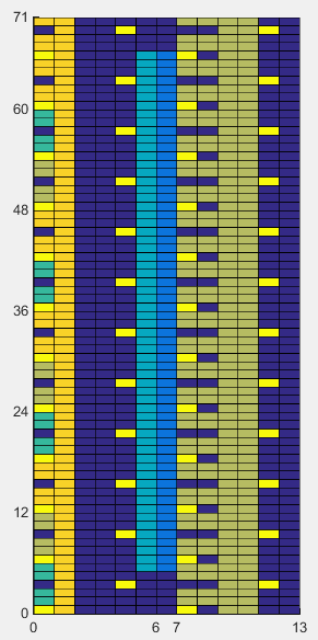
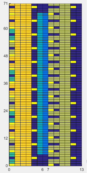
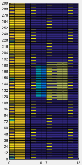
The first set of examples shows the location of PDCCH Resource Elements in 1.4 Mhz BW. The orange REs in the symbol 0~1 in left side and 0~3 symbols in right side represents PDCCH.
|
enb.NCellID = 0; enb.CellRefP = 1; enb.PHICHDuration = 'Normal'; enb.Ng = 'Sixth'; enb.NDLRB = 6; enb.CFI = 1; |
enb.NCellID = 0; enb.CellRefP = 1; enb.PHICHDuration = 'Normal'; enb.Ng = 'Sixth'; enb.NDLRB = 6; enb.CFI = 3; |
|
|
|
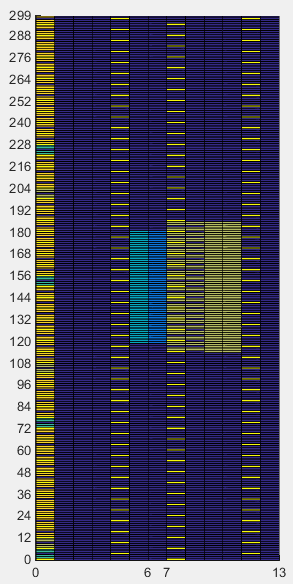
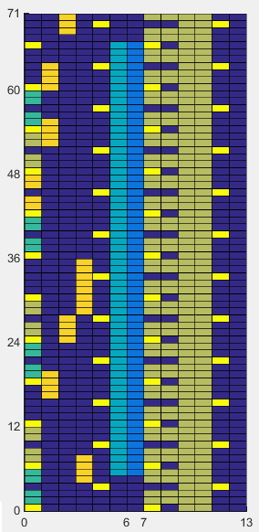
The second set of examples shows the location of PDCCH Resource Elements in 5.0 Mhz BW. The orange REs in the symbol 0 in left side and 0~2 symbols in right side represents PDCCH.
|
enb.NCellID = 0; enb.CellRefP = 1; enb.PHICHDuration = 'Normal'; enb.Ng = 'Sixth'; enb.NDLRB = 25; enb.CFI = 1; |
enb.NCellID = 0; enb.CellRefP = 1; enb.PHICHDuration = 'Normal'; enb.Ng = 'Sixth'; enb.NDLRB = 25; enb.CFI = 3; |
|
|
|
The previous example shows the all the possible PDCCH REs, if you modify just one line as shown below. you can display the REs that are allocated for the specific PDCCH.
pss_scale = 0.2;
sss_scale = 0.4;
phich_scale = 0.7;
pcfich_scale = 0.5;
pbch_scale = 0.7;
pdcch_scale = 0.9;
resourceGrid(pss_sym_ind) = pss_scale;
resourceGrid(sss_sym_ind) = sss_scale;
resourceGrid(pcfich_sym_ind) = pcfich_scale;
resourceGrid(phich_sym_ind) = phich_scale;
resourceGrid(pbch_sym_ind) = pbch_scale;
resourceGrid(pdcch_sym_ind) = pdcch_scale .* pdcch_sym;
xStep = 0:13;
yStep = 0:(enb.NDLRB*12-1);
surface(xStep,yStep,abs(resourceGrid));
axis([0 13 0 (enb.NDLRB*12-1) 0 1]);
view([0,90]);
set(gca,'xtick',[0 6 7 13]);
set(gca,'ytick',[[0:12:enb.NDLRB*12-1] [enb.NDLRB*12-1]]);
The first set of examples shows the location of PDCCH Resource Elements in 1.4 Mhz BW. The orange REs in the symbol 0~1 in left side and 0~3 symbols in right side represents PDCCH.
|
enb.NCellID = 0; enb.CellRefP = 1; enb.PHICHDuration = 'Normal'; enb.Ng = 'Sixth'; enb.NDLRB = 6; enb.CFI = 1;
dci.NDLRB = enb.NDLRB; dci.DCIFormat = 'Format1A'; dci.AllocationType = 0; dci.Allocation.RIV = 18; dci.ModCoding = 10; dci.HARQNo = 0; dci.NewData = 0; dci.TPCPUCCH = 0; dci.DuplexMode = 'FDD'; dci.NTxAnts = 1; |
enb.NCellID = 0; enb.CellRefP = 1; enb.PHICHDuration = 'Normal'; enb.Ng = 'Sixth'; enb.NDLRB = 6; enb.CFI = 3;
dci.NDLRB = enb.NDLRB; dci.DCIFormat = 'Format1A'; dci.AllocationType = 0; dci.Allocation.RIV = 18; dci.ModCoding = 10; dci.HARQNo = 0; dci.NewData = 0; dci.TPCPUCCH = 0; dci.DuplexMode = 'FDD'; dci.NTxAnts = 1; |
|
|
|

Disclaimer ! :
This page is only to show you the overall logics and visualization for various LTE physical layer channels. I haven't investigated much about verifying about the accuracy.
If you think the code is not so efficient, it is 100% my fault. I haven't made any effort for effiecient code. I just tried to create code as simple as possible for the readers. As you know, easy-to-read code is not always efficient for a specific chipset.
If you find any mistake in terms of accuracy, it is also very highly likely be my fault. Not the problem of Matlab tool box itself.
Any comment and corrections if you find any mistake will be welcome and appreciated.