Beam Management in 5G is a technique mainly used in millimeter-wave (mmWave) communications to optimize the alignment of highly directional transmission and reception beams. It includes processes like beamforming, beam selection, beam switching, and beam tracking, which aim to maintain high-quality communication links despite challenges like path loss, blockages, and rapid changes in user equipment position and orientation.
- Characteristics and Challenges in Beam Management in 5G
- Motivation of using AI/ML for Beam Management
- Use case of AI/ML for Beam Management
- Super-resolution beam prediction
- Beam-Tracking and Predictive Beam-Switching
- Low-Frequency Information Assisted mmWave BeamPrediction
- Application to P1,P2,P3
- Challenges of AI/ML for Beam Management
- TDoc Snapshots
- R1-2400045: Discussion on AIML for beam management
- R1-2400144: Discussion on beam management for AI/ML
- R1-2400171: AI/ML for beam management
- R1-2400376: Specification support for AI/ML for beam management
- Reference
Characteristics and Challenges in Beam Management in 5G
Followings are characteristics and challenges in beam management in 5G.
- In 5G especially for mmWave application, it suffers from much higher pathloss than the lower frequency case
- To compensate for the higher pathloss, we use higher number of antenna elements in both gNB and UE to implement a narrower beam to utilize the high beamforming gain
- But in order to utilize the narrow beams properly, we need to implement good algorithms to select the beam pairs of Tx and Rx that are best aligned to each other and maintain the best alignment.
- However, to maintain the best alighment is super difficult especially when the channel condition changes rapidly ,or direction and position of the mobile device changes rapidly.
- In addition, as the width of beams gets narrower they need to use more numbers of beam to cover a certain area. As a result, searching and tracking the best beam from such a many beam gets more difficult.
- AI/ML(Deam Learning) can be considered as a good solution as an algorithm for beam management in this kind of situation.
Motivation of using AI/ML for Beam Management
Currently we rely on mathemtical method to implment the algorithm to handle the beam management situation mentioned above. However, mathematical method has some drawbacks/limitations like :
- mathematical tools generally rely on idealized assumptions,such as the presence of pure additive white Gaussian noise, which may not be consistent with practical scenarios
In contrast, AI/ML approach would have advantages like :
- DL(Deep Learning) adaptively learns the features of the channel in support of reliable beam-management
- Parameters of DL models capture the high-dimensional features of the propagation scenario,such as blockage locations and shapes in support of reliable beam-management
- DL(Deep Learning) can be utilized to extract the nonlinear features inherent in the angular domain for implementing super-resolution beam-prediction
- DL(Deep Learning) is capable of modeling complex nonlinear factors for beam management whereas mathematical models usually ignores these factors for simplicity.
- DL(Deep Learning) would be able to propose DL-based low-overhead beam-tracking and predictive beam-switching for the complex relationships between the UE’s movement and the channel variations
Use case of AI/ML for Beam Management
In this section, I will talk about some example use case of applying Machine Learning for beam management. I will first present some big picture based on a well-written paper Deep Learning for Beam-Management: State-of-the-Art,Opportunities and Challenges and will add further details and aspects as I learn further.
- Modeling both the angular and time domain features, enabling both super-resolution beam prediction and beam tracking
- Extracting high-dimensional environmental features
Super-resolution beam prediction
This is a technique designed to reduce the overhead of beam training. Beam-training refer to a process where the system tries to find the optimal beam pair (one from the base station (BS) and one from the user equipment (UE)) that maximizes the received power.
What would be the issues or challenges with existing (conventional) method regarding this ? Followings are some of the challenges mentioned in the paper.
Excessive Overhead : The overhead of beam-training poses a significant challenge in millimeter-wave (mmWave) communications. For a mmWave system considering 64 beams at the Base Station (BS) and 8 beams at the User Equipment (UE), 512 measurements are required for finding the optimal beam pair. This complexity is excessive and needs to be reduced.Low Signal-to-Noise Ratio (SNR) : The performance of the conventional methods may degrade due to the low SNR when the true Angle of Arrival (AoA) and Angle of Departure (AoD) of the dominant path does not fall exactly in the middle of the main lobe of any candidate beam.Difficulty in Extracting Useful Information : The leaked power of the beams which are angularly far from the AoA and AoD of the dominant path is low. Hence, it is difficult to extract useful information from the corresponding received signals due to their low SNRs.Beam-Training Overhead : The overhead of wide-beam-training is another challenge. The conventional methods require to consider all the wide beams, which increases the overhead.
How AI/ML can relieve these challenges ? In other words, what are the motivations of applying AI/ML in this area ?
Reducing Beam-Training Overhead : Deep Learning (DL) can be used to predict the optimal high-resolution beam using low-resolution beam-search, thereby reducing the overhead of beam-training. This is particularly useful in mmWave systems where a large number of measurements are required for finding the optimal beam pair.Handling Low Signal-to-Noise Ratio (SNR): DL can be used to model the angular features and convert the output into probabilities. This can help in selecting the maximum-probability beam, thereby improving performance in scenarios where the true Angle of Arrival (AoA) and Angle of Departure (AoD) of the dominant path does not fall exactly in the middle of the main lobe of any candidate beam.Covering the Full Angular Space : DL can be used in a scheme that covers the full 360-degree angular space. This is achieved by using a wide-beam based optimal narrow-beam prediction scheme, where the wide and narrow beams can be naturally regarded as low-resolution and high-resolution beams.Predicting Optimal Beams : DL can be used to predict the optimal narrow beam by considering only the subset of wide beams having high Signal-to-Noise Ratios (SNRs). This can further reduce the wide-beam-training overhead.Modeling Temporal Variations: DL, specifically Long Short-Term Memory (LSTM) networks, can be used to model the temporal AoA and AoD variations. This can help in predicting not only the current optimal narrow beam but also the future optimal wide beam.
An example of this AI/ML model in High level representation is illustrated as shown below.
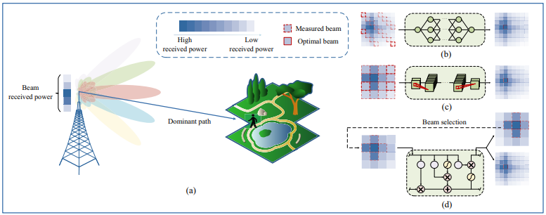
Image Source : Deep Learning for Beam-Management: State-of-the-Art,Opportunities and Challenges
Following is short descriptions on this figure stated in the paper :
(a) An example of the channel’s power leakage;
(b)∼(d) illustration of various super-resolution beam-prediction schemes:
(b) DNN based prediction using fixed angular-spacing beams;
(c) CNN based prediction using wide beams;
(d) LSTM based prediction using partial high-SNR wide beams.
Followings are a little bit more detailed description of the figure :
(a) shows an example of power leakage in a channel and illustrate the challenge of low signal-to-noise ratio (SNR) for beams that are angularly far from the angle of arrival (AoA) and angle of departure (AoD) of the dominant path. It might show how the leaked power of these beams is low, making it difficult to extract useful information from the corresponding received signals.
(b) illustrate the concept of using a fully-connected deep neural network (DNN) to model the angular features of beams with fixed angular spacing. The output of the DNN is then converted into probabilities using a softmax function, and the beam with the maximum probability is selected.
(c) depict the concept of wide-beam based optimal narrow-beam prediction. It could show how a hierarchical multi-resolution codebook is used to conduct a two-level beam-search. The first level aims to find the optimal wide beam, and the second level confirms the specific optimal narrow-beam direction within the range of the selected wide beam.
(d) dipict the concept, where only a subset of wide beams with high SNRs are considered. A long-short term memory (LSTM) network is used to model the temporal AoA and AoD variations. The network predicts not only the optimal narrow beam at the current time slot but also the optimal wide beam for the next time slot.
Beam-Tracking and Predictive Beam-Switching
As the term implies, Beam-Tracking is a technology that tracks beams. What does it mean ? What kind of beams it tracks ? It tracks various beams from transmitter and recievers and find a pair of beam (i.e, TX beam and RX beam) that gives the best performance of data transmission and reception.
Are there any problems or challenges with the current algorithms (i.e, Non-AI/ML based algorithm) that we uses ? Yes, there are many challenges and issues. Only a few example of those issues can be described as follows :
Rapidly Time-Varying Channels : The channels in beam-management change rapidly, requiring frequent beam-training to maintain high-quality services. This poses a significant challenge due to the overhead involved in beam-management.Nonlinearity from UE's Mobility : The mobility of the User Equipment (UE) introduces nonlinearity in the beam-management process. As the UE moves closer to the Base Station (BS), the angular variation of the Line-of-Sight (LOS) path becomes faster, making it difficult to accurately track the beam directions, especially in high-speed scenarios.High-Dimensional Feature Space : The presence of numerous scatterers with diverse locations, sizes, and shapes in wireless environments form a high-dimensional feature space. These scatterers jointly determine the optimal beam direction, making it challenging to model these complex scattering features accurately.Adaptive Fitting Capability : The mobility of users and scatterers, and the dynamic appearance and disappearance of blockages, require beam-management to adapt to the dynamic fluctuations of the environment. Conventional beam-management methods usually detect blockage using a received power threshold and then perform re-sweeping, leading to excessive overhead.
Even if it may not be a perfect solution that can resolve these problems completely, AI/ML technology may be a good candidate for alternative (or at least compensating) technology for beam-tracking.
Then how AI/ML can be possible solutions for this kind of problem ? Followings are some of logic ground for the motivation of applying AI/ML in this area.
Predictive Modeling : ML algorithms can learn from historical data and predict future states. For instance, they can predict the optimal beam direction based on past and current channel state information (CSI), user equipment (UE) location, and movement patterns. This can reduce the need for frequent beam-training, thereby reducing overhead.Handling Nonlinearity : Deep learning is particularly good at modeling nonlinear relationships, which are common in wireless communication systems due to factors like UE's mobility. Neural networks can learn these nonlinear patterns and improve beam-tracking accuracy.High-Dimensional Feature Space : ML algorithms can handle high-dimensional feature spaces effectively. They can learn complex scattering features in wireless environments and use this knowledge to improve beam-management.Adaptive Learning : ML models can adapt to new data and changes in the environment. For instance, reinforcement learning algorithms can interact with the environment and learn optimal policies over time, improving beam-management in dynamic scenarios.
Low-Frequency Information Assisted mmWave BeamPrediction
When we deploy 5G in an NSA mode with FR2 (mmWave), the system works both in low frequency (LTE) and mmWave (NR) frequency simulteneously.
One of idea of utilizing this system in terms of Beam Prediction is 'Measure and collect the information about the beam in low frequency LTE and use that information to predict beam in mmWave frequency' ?
How you come up with this idea ? What would be the motivation for this approach ? There can be some advatange of measuring and collecting those information in low frequency rather than doing directly in mmWave as follows.
Shared Environmental Features : The low-frequency and mmWave links perceive similar propagation environments. This allows the use of low-frequency channel information to infer environmental features that can assist in mmWave beam-management.Reduced Complexity : The use of low-frequency information can reduce the complexity of beam prediction in mmWave systems. This is because low-frequency systems typically have fewer antennas and thus fewer potential beam directions to consider.Improved Accuracy : The use of low-frequency information can improve the accuracy of beam prediction in mmWave systems. This is because low-frequency signals are less susceptible to blockages and can provide more reliable information about the propagation environment.
OK, now I think I can understand the idea on utilizing low frequency information to predict mmWave beam. Another question popping up in my mind is 'Why you want to use AI/ML for this purpose instead of deterministic mathematical model ?'.
The main motivation would be due to the complex relationships between the low-frequency and the mmWave channels, which cannot easily be modeled by conventional mathematical modeling.
An example of this AI/ML model in High level representation is illustrated as shown below.
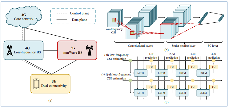
Image Source : Deep Learning for Beam-Management: State-of-the-Art,Opportunities and Challenges
Following is short descriptions on this figure stated in the paper :
(a) NSA architecture;
(b) CNN based mmWave beam-prediction using low-frequency CSI;
(c) cascaded LSTM based mmWave beam-tracking using low-frequency CSI.
In the paper mentioned above, it was not clear to me on how CNN and LSTM is combined. I think the diagram in the following paper gives a better representation on how CNN and LSTM are combined in this application.
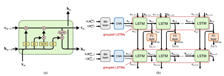
Image Source : Deep Learning Assisted mmWave Beam Prediction with Prior Low-frequency Information
Following is short descriptions on this figure stated in the paper :
(a) Basic structure of LSTM.
(b) Proposed deep learning model design
In this machine learning model, there are two major components. One is to extract the information from low frequency radio channel and another one is to apply that information to predict beams in mmWave channel. These two parts use different deep learning model and are combined in the structure as shown above. Followings are high level descriptions on this structure.
Convolutional Neural Networks (CNN) and Long Short-Term Memory (LSTM) networks are used in different ways to improve beam prediction and tracking in mmWave communication systems. CNNs are used to process variable-length CSI and extract hidden features, while LSTM networks are used to track and predict the optimal mmWave beam based on previous CSI sequences.
CNN : The CNN is used to process variable-length Channel State Information (CSI). Given that the length of the low-frequency CSI can dynamically vary, a dedicated CNN is proposed to handle this variable-length CSI-input. Convolutional layers are utilized to extract hidden features from the low-frequency CSI. Then, a fully connected (FC) layer is adopted to match the size of the extracted features to the specific number of candidate beams. A scalar pooling layer is introduced after the convolutional layers, which downsamples the extracted features to a scalar, thus guaranteeing the efficient support of variable-length CSIs.LSTM : The LSTM network is used for tracking the optimal mmWave beam using the previous low-frequency CSI sequence. At each beam-tracking action, the LSTM network is exploited for fusing the previous CSI estimates and sensor measurements to extract the UE’s movement features for predicting the a-priori AoA distribution. Based on this predicted distribution, the future beams are predicted and then measured for creating the more accurate a-posteriori estimate from the a-priori CSI estimate by using sequential Bayesian estimation. This scheme integrates the expert knowledge of classical mathematical models with the adaptive fitting capability of DL, and thus achieves lower tracking errors than the conventional DL-based scheme that only relies on training data.
Application to P1,P2,P3
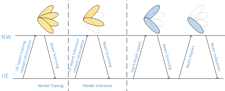
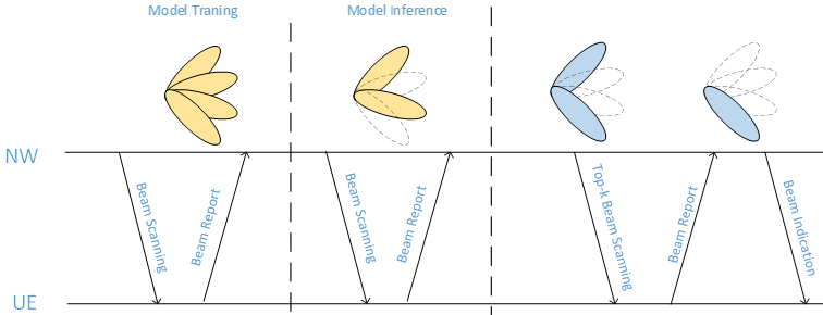
One example of AI/ML to existing beam management process P1,P2,P3 is presented in An Overview of the 3GPP Study on Artificial Intelligence for 5G New Radio as illustrated below.
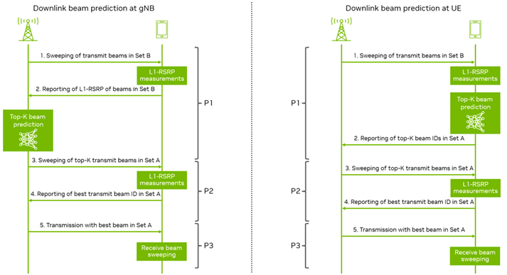
Image Source : An Overview of the 3GPP Study on Artificial Intelligence for 5G New Radio
This illustration shows the two cases (examples) of applying AI/ML for beam management. Both procedures are part of the NR beam management framework and include three known procedures: P1 for initial beam pair establishment, P2 for transmit beam refinement, and P3 for receive beam refinement. The key difference between gNB and UE prediction is where the AI/ML model inference occurs and who reports to whom. In the gNB case, the UE reports measurements to the gNB for AI/ML prediction. In the UE case, the UE itself predicts and reports the results to the gNB. This predictive process can reduce overhead and latency in beam selection, leading to more efficient network operation.
Each of the cases goes through a sequence of steps as follows :
Downlink Beam Prediction at gNB: Step 1 : The gNB sweeps through transmit beams in Set B to gather data.Step 2 : The UE reports the L1-RSRP (Layer 1 Reference Signal Received Power) measurements of these beams back to the gNB.Step 3 : The gNB uses an AI/ML model to predict the top-K transmit beams in Set A based on the L1-RSRP measurements.Step 4 : The gNB sweeps through the predicted top-K transmit beams in Set A, and the UE measures these beams to identify the best one.Step 5 : The UE reports the ID of the best transmit beam in Set A back to the gNB.Receive Beam Sweeping : The UE then sweeps through different receive beams to find the best receive beam that pairs with the chosen transmit beam.Downlink Beam Prediction at UE: Step 1 : Similar to the gNB side, the UE sweeps through transmit beams in Set B.Step 2 : The UE uses its own AI/ML model to predict the top-K transmit beams in Set A from the L1-RSRP measurements.Step 3 : The UE sweeps through the predicted top-K transmit beams in Set A to find the best one.Step 4 : The UE reports the ID of the best transmit beam in Set A back to the gNB.Step 5 : The UE transmits with the best beam in Set A.Receive Beam Sweeping : Similar to the gNB side, the UE searches for the best receive beam to use.
Challenges of AI/ML for Beam Management
Even though we see a lot of new opportunities from applying AI/ML for Beam Management, there would be various challenges to be overcome as in almost any technologies.
Even though these would be challenges in terms of implementation of technolgy itself, they can provide opportunities for researchers as new research items in this area.
Again the paper Deep Learning for Beam-Management: State-of-the-Art,Opportunities and Challenges well summarizes about this and I will start quoting from this paper and will add additional comments or informations as I learn further.
Model Compression : Given the UE’s mobility, beam-alignment is usually refreshed every dozen of milliseconds or so. Therefore, DL must be completed within this period for ensuring prompt beam-alignment. To meet this high complexity requirement, DL has to be deployed at the BS, which has powerful computational capability. Nonetheless, reducing the numerous model parameters must be further investigated.- "Model Compression" in the context of machine learning refers to the process of reducing the complexity of a machine learning model. This can involve reducing the number of parameters, changing the structure of the model, or using other techniques to make the model smaller or simpler. The goal is to create a model that performs as well as the original model but is faster to run and requires less computational resources.
- In this context, it is being discussing about the need for model compression in the context of beam management. Given the high mobility of user equipment (UE), beam alignment needs to be refreshed frequently, often every few milliseconds. This means that any deep learning (DL) model used for beam alignment needs to complete its predictions within this short time frame.
- To meet this requirement, the DL model would likely need to be deployed at the base station (BS), which has more computational power. However, even with this additional power, the model may still be too complex to run within the required time frame. This is where model compression comes in. By reducing the complexity of the model, it can run faster and meet the time requirements for beam alignment.
- So, while "Model Compression" does relate to time constraints, it's more about how to meet those constraints by making the model simpler and faster to run.
Model Generalization : The optimal beam angle depends on the propagation environment. Naturally, each BS and UE best collects its own training data comprising the specific environmental features for optimizing the local model, but collecting huge amounts of training data imposes excessive cost. Therefore, transfer-learning can be adopted for applying the knowledge extracted from one environment to another one, so that satisfactory performance can be achieved, despite using only limited training sets.- Transfer learning is a machine learning method where a pre-trained model is used as the starting point for a model on a second task. It's like saying, "Use the knowledge you gained from this task, and apply it to this slightly different task." This can reduce the amount of data needed and the cost of data collection.
- The term "Model Generalization" in this context is about creating a model that can take what it has learned from one environment (or task) and apply it to another, effectively generalizing the learned knowledge.
Multi-modal Integration : Next-generation terminals will support multiple radio frequency (RF) bands, such as 900MHz for voice calls, 2.3GHz for basic data services, 28GHz and beyond for high-speed access, where different bands interact with the environment in different manners. Therefore, the fusion of various bands assists in characterising the propagation environment more precisely, in order to facilitate accurate beam-alignment. Moreover, the UE’s sensor measurements can provide further efficient auxiliary information for beam-management.- "Multi-modal Integration" in the context of machine learning refers to the process of combining information from different sources or types of data, often referred to as "modalities". The goal is to create a more comprehensive and accurate model by leveraging the strengths and compensating for the weaknesses of each modality.
- In this context, it is discussed about the need for multi-modal integration in the context of beam management. 5G terminals will support multiple radio frequency (RF) bands, such as 900MHz for voice calls, 2.3GHz for basic data services, and 28GHz and even beyond for high-speed access. Each of these bands interacts with the environment in different ways, and thus, the data they provide about the environment will be different.
- By integrating data from all these different bands, a more accurate and comprehensive characterization of the propagation environment can be achieved. This would, in turn, facilitate more accurate beam alignment. The authors also mention that sensor measurements from the user equipment (UE) can provide additional useful information for beam management.
- So, "Multi-modal Integration" in this context is about combining data from different RF bands and possibly other sources to improve the accuracy and effectiveness of beam management. This is a common approach in machine learning, where combining different types of data often leads to better performance than using any single type of data alone.
Interference Management : In contrast to the omni-directional antenna used in low-frequency links, highly directional antennas are used in mmWave links, which results in different interference patterns. Therefore, the interference management strategy of low-frequency links cannot be directly applied to mmWave links.- "Interference Management" in the context of wireless communication refers to the techniques used to minimize the impact of interference on signal quality. Interference can occur when signals from different sources overlap and disrupt each other, reducing the quality of the received signal.
- In this context, it is discussed of the challenge of interference management in the context of beam management. They mention that the interference patterns in millimeter wave (mmWave) links are different from those in low-frequency links due to the use of highly directional antennas in mmWave links, as opposed to the omni-directional antennas used in low-frequency links.
- This means that the interference management strategies that work for low-frequency links cannot be directly applied to mmWave links. Therefore, new strategies need to be developed for managing interference in mmWave links. This could involve using machine learning techniques to predict and mitigate interference, or it could involve developing new hardware or software solutions.
- So, "Interference Management" in this context is about developing strategies to minimize the impact of interference on the quality of mmWave links, which is a key aspect of beam management. This is a significant challenge due to the unique characteristics of mmWave communication, but it also presents opportunities for innovation and improvement.
TDoc Snapshots
TDoc gives a lot of insights and intuitive explanations that are not usually provided by TS (Test Specification) but in many cases you may feel difficulties to catch up what a TDoc is talking about unless you tracked down the topics from the beginning. The discussions in TDocs proceed incrementaly and refer to many terms in previous TDocs without the detailed explanations. In order to catch up the document, I would suggest you to give careful readings on several TDocs released at the very early discussion and get familiar with core concepts and key terminologies. In this section, I want to note those core concepts and terminologies from TDoc based on my personal criteria.
R1-2400045: Discussion on AIML for beam management
This is one of the earliest TDocs on AI/ML for beam management and describes big picture on the overal purpose and high level logics.
BM Case 1 vs BM Case 2
Beam management - DL Tx beam prediction for both UE-sided model and NW-sided model, encompassing [RAN1/RAN2]:Spatial-domain DL Tx beam prediction for Set A of beams based on measurement results of Set B of beams (“BM-Case1 ”) => This is to predict some non-measured beam(Set A) from measured Beams(Set B) in spatial domain at a specific timingTemporal DL Tx beam prediction for Set A of beams based on the historic measurement results of Set B of beams (“BM-Case2 ”) => This is to predict some non-measured beam(Set A) from measured Beams(Set B) in time domainSpecify necessary signalling/mechanism(s) to facilitate LCM operations specific to the Beam Management use cases, if anyEnabling method(s) to ensure consistency between training and inference regarding NW-side additional conditions (if identified) for inference at UE
Summary of Terminology. These are short descriptions of keywords that will always pop up in every TDocs on AI/ML Beam Management
BM-Case 1 : Spatial DL Beam predictionBM-Case 2 : Temporal DL Beam PredictionSet B : Set of Beams used for Measurement (i.e, Measured Beams)Set A : Set of Beam targeted for Prediction
UE side model vs Network side model
Both model training and inference are carried out by UE.
Both model training and inference are carried out by NW.
R1-2400144: Discussion on beam management for AI/ML
This documents outlines a comprehensive set of enhancements, observations, and proposals aimed at advancing Artificial Intelligence/Machine Learning (AI/ML) based beam management within the 5G network. It addresses the integration and specification needs for both network-side (NW-side) and user equipment-side (UE-side) models to improve beam prediction and management through AI/ML technologies.
Following illustration depicts the association between Set A and Set B during the AI training phase. The figure essentially illustrates the data collection process for AI training, where the measurements from a smaller set of beams are used to predict the best beam from a larger set, facilitating efficient beam management in the 5G network.
< Association of Set A to Set B >
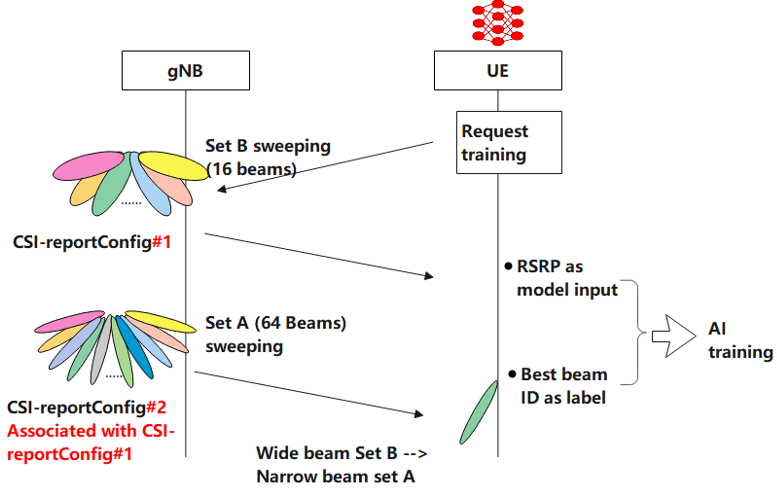
Followings are high level description for the illustation :
CSI-reportConfig#1 : This configuration pertains to Set B, which consists of 16 beams. These are the beams the UE is tasked to measure and report back to the gNB. The sweeping action indicates that the gNB directs the UE to scan these beams and gather signal information.CSI-reportConfig#2 Associated with CSI-reportConfig#1 : This is Set A, which includes a larger number of beams (64 in this case). This configuration is associated with CSI-reportConfig#1, meaning that the data collected from Set B will be used in relation to Set A for AI training purposes.AI Training : The process where the UE uses RSRP measurements from Set B as input data for the AI model. The best beam ID identified from Set A acts as the label for the training data. Essentially, the AI uses the quality of the signal from Set B to predict the optimal beam from a larger set (Set A).Data Flow :-
The gNB instructs the UE to measure and report the RSRP from the 16 beams in Set B.
-
Separately, the gNB also has a configuration for Set A, consisting of a wider set of 64 beams. This larger set is used for more detailed measurement and AI model training.
-
The UE performs the measurements and sends the data back to the gNB, which uses this information to associate the results from Set B to Set A.
-
This association is used to train the AI model, where RSRP measurements are the input and the best beam ID from Set A is the desired output (label).
This illustration shows the mapping of Set B within Set A in the context of AI/ML-based beam management. This mapping and prediction process is to reduce overhead and improve the quality of the connection between the UE and the network. The result of the AI training should ideally be that the AI model can accurately predict the best communication beam from Set A using the measurement data from Set B, resulting in more efficient beam management and enhanced network performance.
< Mapping of Set B within Set A >
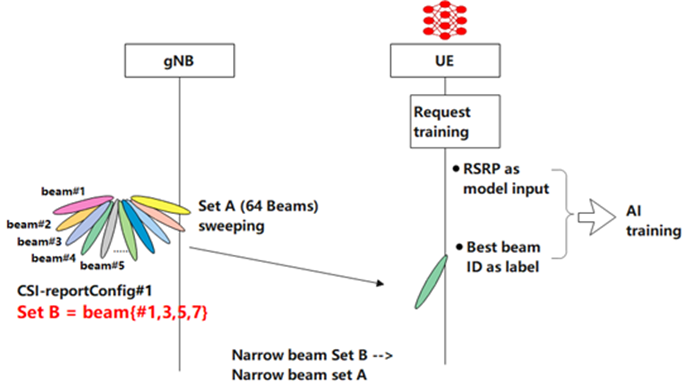
Followings are high level description for the illustation :
Set A (64 Beams) : This represents a larger set of narrow beams from which the base station can choose for communication with the UE. The gNB performs sweeping across all these beams to collect signal data.CSI-reportConfig#1 : This is a configuration set up by the gNB for the UE to report on the beams. In this case, Set B is defined under this configuration.Set B = beam(#1,3,5,7) : Set B is a subset of Set A, and it includes beams numbered 1, 3, 5, and 7 in this example. These beams are part of the beam sweeping process, and their measurements will be used specifically for AI training.AI Training : The UE uses RSRP from Set B as input for the AI training. The goal is to determine the best beam ID from Set A based on the quality of signal received from Set B, thereby enabling the AI to learn and predict which beam from Set A would be optimal for future communication.Data Flow and Association: -
The gNB instructs the UE to perform measurements on Set B beams (1, 3, 5, 7).
-
The UE sends the RSRP measurements of these beams back to the gNB.
-
The gNB associates these measurements with the larger Set A for AI training, which involves using the signal information from the smaller subset (Set B) to predict the best beam from the larger set (Set A).
R1-2400171: AI/ML for beam management
This documents focuses on providing a general framework for AI/ML models, detailing the signalling and protocol aspects necessary for Life Cycle Management (LCM) of these models, and enhancing the positioning accuracy through AI/ML. The document aims to improve the downlink (DL) transmission beam prediction for both UE-sided and network-sided models by specifying the necessary signalling mechanisms for LCM operations and ensuring consistency between training and inference phases for AI/ML models.
Followings are high level summary of this document.
Signalling Enhancement for NW-sided Model
Consistency from Training to Inference: It addresses the need for ensuring consistency between the training and inference phases for NW-sided models. Strategies include UE indication of RxBeamIndex during data collection and a fixed Rx-beam use by the UE upon network instruction.Mitigating RSRP Measurement Errors : Discusses the impact of RSRP measurement errors on prediction performance and suggests tightening RSRP measurement accuracy requirements.Inference Data Collection Enhancements : Proposes extending the IE nrofReportedRS in 38.331 to support reporting on more than 4 beams, using 256 beams as a starting point for BM-case2 scenarios.Reducing Reporting Overhead : Explores options for pre-configured or dynamic selection of Set B beams to reduce reporting overhead, suggesting methods for UE to report only the strongest beams or those within a certain dB range of the strongest beam.Temporal and Spatial Domain Predictions : Proposes support for UEs to compress temporal domain measurement results and to configure reporting based on spatial domain predictions to reduce reporting overhead.UE Assistance Information : Considers the types of assistance information that could be provided by the UE to the NW, such as location, moving direction, and Rx beam shape/direction, but acknowledges a lack of consensus due to privacy concerns.
Signalling Enhancement for UE-sided Model
Consistency Between Training and Inference : Emphasizes the need for model consistency, including model identification and handling NW-side additional conditions. It suggests solutions like model training at the NW and transferring to UE, along with providing information on NW-side additional conditions.Handling Additional Conditions : Discusses the challenge of different antenna/beam configurations across cells and proposes ways to enable UE models to generalize across various scenarios.Data Collection and Association Mapping : Outlines the need for specific signalling for data collection related to Set A and Set B beams, and how these sets are associated and mapped for AI/ML models.Model Inference and Performance Monitoring : Suggests enhanced configurations, reporting, and measurement for model inference. It also discusses how to report AI/ML inference output, including predicted beam indices, time validity of predictions, uncertainty of predictions, and predicted RSRP.NW Assistance for UE Models : Notes the deferred discussion on NW assistance information until methods for ensuring training and inference consistency are concluded. It touches on the importance of NW-side information in helping UE models adjust to varying conditions.
R1-2400376: Specification support for AI/ML for beam management
In this document, more detailed description and insights on each of BM cases are provided
BM-Case 1: Spatial Domain Beam Prediction
<ML Aided Beam Prediction at gNB with Model residing at the gNB>
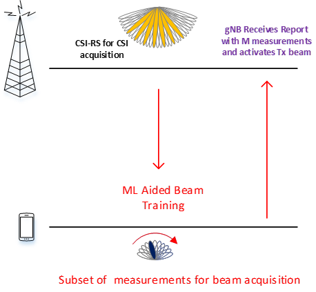
- gNB triggers CSI-RS for CSI based on periodic/aperiodic beam report from UE if Tx beam drops below threshold
- gNB transmits M CSI-RS based on a set B of beams where M << cardinality of set A of total number of CSI-RS beams
- UE measures L1-RSRP/SINR and reports to gNB
- gNB can use M measurement or a function of the measurements as input to the gNB-side AI/ML model to predict best or top-K Tx (Rx) beam
BM-Case 1a: Set B ⊆ Set A
<Narrow Beam Prediction from Narrow Beam Measurements>
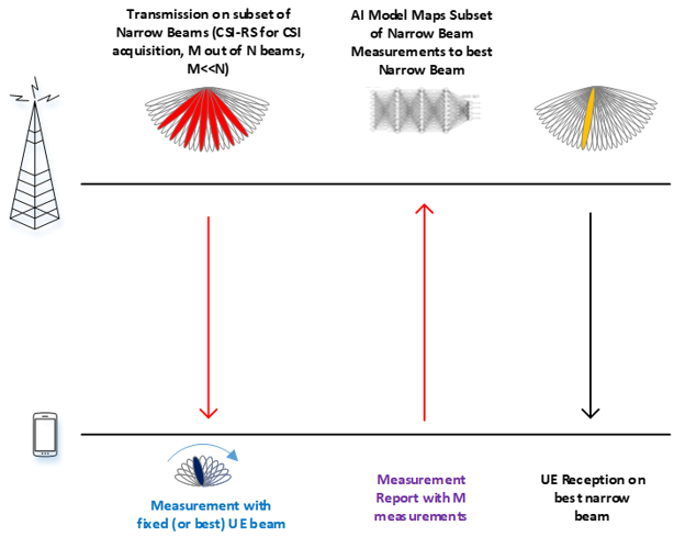
Input Formation : The input to the AI/ML model(Set B) consists of beams that are part of Set A.Use Case Explanation : This setup is typically used when narrow analog beam measurements from CSI-RS transmissions are employed to predict the best narrow beamsModel Training : The AI/ML model is trained to map a subset of these measurements to either:- All the measurements for beams in Set A, or
- The index of the best beam within Set A.
Data Collection and Measurement Protocol : CSI-RS is utilized for both the measurement and data collection processes in this scenario.Specification Impact : CSI-RS transmissions for set B measurements and consequent overhead reduction from smaller number of required measurements
BM-Case 1a: Set B ∉ Set A
<Narrow Beam Prediction from Wide Beam Measurements>
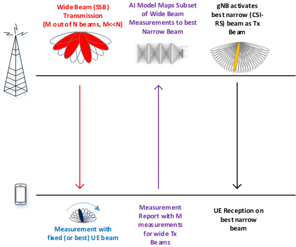
Input Formation : The input to the AI/ML model(Set B) is based on a different analog beamforming assumption compared to Set A.Measurement Assumptions : Measurements for Set B are assumed to be on wide SSB beams.AI/ML Functionality : The AI/ML model uses these wide SSB beam measurements from Set B to predict the best narrow CSI-RS beam, which is intended for data transmission.Latency Reduction : This method can potentially reduce the latency of initial access procedures. It allows UE to measure fewer SSBs while directly providing the best CSI-RS beam for further communication.Specification Impact: - Impacts stem from the configuration of Set B and the simplifications of the initial access procedure.
- Reduction in latency is achieved through a smaller number of measurements needed to predict the best narrow CSI-RS beam.
BM-Case 2: Temporal Domain Beam Prediction
< Temporal Domain Beam Prediction with L1-RSRP >
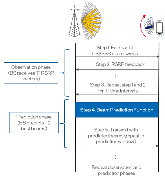
< AIML-based Temporal Domain Beam Prediction >
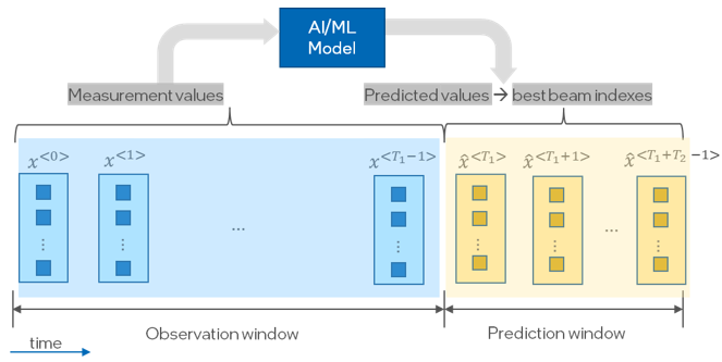
Beam Prediction Method : A temporal domain beam prediction method is used to predict the beams for future transmission and reception by the base station (BS) and/or UE.Two-Phase Process: Observation Phase : Measurements such as L1-RSRP are collected.Prediction Phase : The collected measurements are fed into a beam prediction model which then generates predicted beams. These beams are used by the BS and/or UE to transmit and receive data.Implementation Locations : The beam prediction can be implemented at the BS side, the UE side, or both.AI/ML Implementation :- Measurements from the observation window are input into an AI/ML model.
- The model predicts the measurements for the prediction window.
- These predictions help infer the best beam or set of beams for use, as illustrated in the figure.
Configuration Requirements :- Necessary to enable configuration of the observation and prediction windows.
- Depending on the model’s location (BS or UE), appropriate configurations may be required.
Model Mobility and Configuration :- If the model is transferred from one node to another, configuration of model selection at the inference node may be required based on different lengths of prediction and/or observation windows.
UE-Specific Considerations: - If the model resides at the UE-side, the UE may need to trigger aperiodic reference signal transmissions from the gNB (next generation NodeB) during the observation phase to perform necessary measurements.
Reference
3GPP TR/TS/General - 3GPP - Finding AI in 3GPP
- 3GPP - RAN3 completes AI & ML support study
- 3GPP - AI/ML for NR Air Interface
- 3GPP TR 22.874 - Study on traffic characteristics and performance requirements for AI/ML model transfer in 5GS (Release 18)
- 3GPP TR 28.908 Study on Artificial Intelligence / Machine Learning (AI/ML) management (Release 18)
- 3GPP TR 38.843 - Study on Artificial Intelligence (AI)/Machine Learning (ML) for NR air interface
- 3GPP TS 28 105 - Artificial Intelligence/ Machine Learning (AI/ML) management
- 3GPP RP-221348 Study on Artificial Intelligence (AI)/Machine Learning (ML) for NR Air Interface
3GPP TDocs - R1-2204060 : 3GPP TSG RAN WG1 #109-e e-Meeting, Beam management with AI/ML
- TSG RAN WG1 #116
- R1-2401766 : Session notes for 9.1 (Artificial Intelligence (AI)/Machine Learning (ML) for NR Air Interface) - TSG RAN WG1 #116 – February 26th – March 1st, 2024
- R1-2401599 - FL summary #3 for AI/ML in management : 3GPP TSG RAN WG1 #116 - February 26th – March 1st, 2024
- R1-2401598 : FL summary #1 for AI/ML in management - 3GPP TSG RAN WG1 #116 February 26th – March 1st, 2024
- R1-2401597 : FL summary #1 for AI/ML in management - 3GPP TSG RAN WG1 #116 February 26th – March 1st, 2024
- R1-2401596 : FL summary #1 for AI/ML in management - 3GPP TSG RAN WG1 #116 February 26th – March 1st, 2024
- R1-2401573 : Final Summary for other aspects of AI/ML model and data - 3GPP TSG RAN WG1 #116 February 26th – March 1st, 2024
- R1-2401572 : Summary #4 for other aspects of AI/ML model and data - 3GPP TSG RAN WG1 #116 February 26th – March 1st, 2024
- R1-2401571 : Summary #3 for other aspects of AI/ML model and data - 3GPP TSG RAN WG1 #116 February 26th – March 1st, 2024
- R1-2401570 : Summary #2 for other aspects of AI/ML model and data - 3GPP TSG RAN WG1 #116 February 26th – March 1st, 2024
- R1-2401569 : Summary #2 for other aspects of AI/ML model and data - 3GPP TSG RAN WG1 #116 February 26th – March 1st, 2024
- R1-2401431 : Specification support for AI-ML-based beam management - 3GPP TSG RAN WG1 #116 February 26th – March 1st, 2024
- R1-2401430 : Work plan for Rel-19 WI on AI and ML for NR air interface - 3GPP TSG RAN WG1 #116 February 26th – March 1st, 2024
- R1-2401179 : Discussion on support for AI/ML beam management - 3GPP TSG RAN WG1 #116 February 26th – March 1st, 2024
- R1-2401153 : Discussion on Specification Support of AI/ML for Beam Management- 3GPP TSG RAN WG1 #116 February 26th – March 1st, 2024
- R1-2401134 : Discussions on AI/ML for beam management- 3GPP TSG RAN WG1 #116 February 26th – March 1st, 2024
- R1-2401002 : Discussion on AI/ML beam management - 3GPP TSG RAN WG1 #116 February 26th – March 1st, 2024
- R1-2400831 : AI/ML specification support for beam management - 3GPP TSG RAN WG1 #116 February 26th – March 1st, 2024
- R1-2400720 : Discussion for supporting AI/ML based beam management - 3GPP TSG RAN WG1 #116 February 26th – March 1st, 2024
- R1-2400618 : On specification for AI/ML-based beam management - 3GPP TSG RAN WG1 #116 February 26th – March 1st, 2024
- R1-2400418: Discussion on AI/ML-based beam management - 3GPP TSG RAN WG1 #116 February 26th – March 1st, 2024
- R1-2400392: ML based Beam Management - 3GPP TSG RAN WG1 #116 February 26th – March 1st, 2024
- R1-2400376: Specification support for AI/ML for beam management - 3GPP TSG RAN WG1 #116 February 26th – March 1st, 2024
- R1-2400263: Discussion on specification support for AI/ML beam management - 3GPP TSG RAN WG1 #116 February 26th – March 1st, 2024
- R1-2400171: AI/ML for beam management - 3GPP TSG RAN WG1 #116 February 26th – March 1st, 2024
- R1-2400144: Discussion on beam management for AI/ML - 3GPP TSG RAN WG1 #116 February 26th – March 1st, 2024
- R1-2400045: Discussion on AIML for beam management- 3GPP TSG RAN WG1 #116 February 26th – March 1st, 2024
- 3GPP TSG-RAN WG1 Meeting #118bis
- R1-2407653 : Discussion on AI/ML for beam management - 3GPP TSG-RAN WG1 Meeting #118bis - October 14th – 18th, 2024
- R1-2407657 : Discussion on other aspects of the additional study for AI/ML -3GPP TSG-RAN WG1 Meeting #118bis - October 14th – 18th, 2024
- R1-2407694 : Discussion on AIML for beam management -3GPP TSG-RAN WG1 Meeting #118bis - October 14th – 18th, 2024
- R1-2407697 : Discussion on other aspects of AI/ML model and data-3GPP TSG-RAN WG1 Meeting #118bis - October 14th – 18th, 2024
- R1-2407728 : Discussion on AI/ML for beam management -3GPP TSG-RAN WG1 Meeting #118bis - October 14th – 18th, 2024
- R1-2407852 : Other aspects of AI/ML model and data -3GPP TSG-RAN WG1 Meeting #118bis - October 14th – 18th, 2024
- R1-2407896 : Discussion on other aspects of AI/ML model and data-3GPP TSG-RAN WG1 Meeting #118bis - October 14th – 18th, 2024
- R1-2407938 : Discussion on AI/ML beam management-3GPP TSG-RAN WG1 Meeting #118bis - October 14th – 18th, 2024
- R1-2407941 : Discussion on other aspects of AI/ML in NR air interface-3GPP TSG-RAN WG1 Meeting #118bis - October 14th – 18th, 2024
- R1-2407954 : Further study on AI/ML model and data-3GPP TSG-RAN WG1 Meeting #118bis - October 14th – 18th, 2024
- R1-2407988 : ML based Beam Management-3GPP TSG-RAN WG1 Meeting #118bis - October 14th – 18th, 2024
- R1-2407992 : ML Model and Data - 3GPP TSG-RAN WG1 Meeting #118bis - October 14th – 18th, 2024
- R1-2408027 : Discussion on AI/ML-based beam management - 3GPP TSG-RAN WG1 Meeting #118bis - October 14th – 18th, 2024
- R1-2408031 : Study on AI/ML for other aspects - 3GPP TSG-RAN WG1 Meeting #118bis - October 14th – 18th, 2024
- R1-2408158 : On specification for AI/ML-based beam management - 3GPP TSG-RAN WG1 Meeting #118bis - October 14th – 18th, 2024
- R1-2408162 : Additional study on other aspects of AI/ML model and data - 3GPP TSG-RAN WG1 Meeting #118bis - October 14th – 18th, 2024
- R1-2408222 : Discussion on other aspects of AI/ML model and data - 3GPP TSG-RAN WG1 Meeting #118bis - October 14th – 18th, 2024
- R1-2408268 : AI/ML for beam management - 3GPP TSG-RAN WG1 Meeting #118bis - October 14th – 18th, 2024
- R1-2408269 : Discussion on other aspects of AI/ML - 3GPP TSG-RAN WG1 Meeting #118bis - October 14th – 18th, 2024
- R1-2408279 : Discussion on AI/ML for beam management - 3GPP TSG-RAN WG1 Meeting #118bis - October 14th – 18th, 2024
- R1-2408432 : Discussion on other aspects of AI/ML model and data - 3GPP TSG-RAN WG1 Meeting #118bis - October 14th – 18th, 2024
- R1-2407938 : Discussion on AI/ML beam management-3GPP TSG-RAN WG1 Meeting #118bis - October 14th – 18th, 2024
- R1-2408456 : Further study on AI/ML model and data - 3GPP TSG-RAN WG1 Meeting #118bis - October 14th – 18th, 2024
- R1-2407988 : ML based Beam Management-3GPP TSG-RAN WG1 Meeting #118bis - October 14th – 18th, 2024
- R1-2407992 : ML Model and Data - 3GPP TSG-RAN WG1 Meeting #118bis - October 14th – 18th, 2024
- R1-2408027 : Discussion on AI/ML-based beam management - 3GPP TSG-RAN WG1 Meeting #118bis - October 14th – 18th, 2024
- R1-2408031 : Study on AI/ML for other aspects - 3GPP TSG-RAN WG1 Meeting #118bis - October 14th – 18th, 2024
- R1-2408158 : On specification for AI/ML-based beam management - 3GPP TSG-RAN WG1 Meeting #118bis - October 14th – 18th, 2024
- R1-2408162 : Additional study on other aspects of AI/ML model and data - 3GPP TSG-RAN WG1 Meeting #118bis - October 14th – 18th, 2024
- R1-2408222 : Discussion on other aspects of AI/ML model and data - 3GPP TSG-RAN WG1 Meeting #118bis - October 14th – 18th, 2024
- R1-2408268 : AI/ML for beam management - 3GPP TSG-RAN WG1 Meeting #118bis - October 14th – 18th, 2024
- R1-2408269 : Discussion on other aspects of AI/ML - 3GPP TSG-RAN WG1 Meeting #118bis - October 14th – 18th, 2024
- R1-2408279 : Discussion on AI/ML for beam management - 3GPP TSG-RAN WG1 Meeting #118bis - October 14th – 18th, 2024
- R1-2408292 : Other aspects of AI/ML model and data - 3GPP TSG-RAN WG1 Meeting #118bis - October 14th – 18th, 2024
- R1-2408363 : Discussion on AI/ML for CSI compression - 3GPP TSG-RAN WG1 Meeting #118bis - October 14th – 18th, 2024
- R1-2408390 : Specification support for AI-enabled beam management - 3GPP TSG-RAN WG1 Meeting #118bis - October 14th – 18th, 2024
- R1-2408394 : Additional study on other aspects of AI model and data(*)- 3GPP TSG-RAN WG1 Meeting #118bis - October 14th – 18th, 2024
- R1-2408401 : Discussions on AI/ML for beam management - 3GPP TSG-RAN WG1 Meeting #118bis - October 14th – 18th, 2024
- R1-2408428 : AI/ML specification support for beam management(*)- 3GPP TSG-RAN WG1 Meeting #118bis - October 14th – 18th, 2024
- R1-2408432 : Discussion on other aspects of AI/ML model and data - 3GPP TSG-RAN WG1 Meeting #118bis - October 14th – 18th, 2024
- R1-2408438: On other aspects of AI/ML model and data - 3GPP TSG-RAN WG1 Meeting #118bis - October 14th – 18th, 2024
- R1-2408452: Discussion on AI/ML beam management - 3GPP TSG-RAN WG1 Meeting #118bis - October 14th – 18th, 2024
- R1-2408456: Discussion on other aspects of AI/ML model and data - 3GPP TSG-RAN WG1 Meeting #118bis - October 14th – 18th, 2024
- R1-2408522: Discussion on support for AI/ML positioning - 3GPP TSG-RAN WG1 Meeting #118bis - October 14th – 18th, 2024
- R1-2408541: Discussion on other aspects of AI/ML for air interface - 3GPP TSG-RAN WG1 Meeting #118bis - October 14th – 18th, 2024
- R1-2408544: AI/ML for Beam Management - 3GPP TSG-RAN WG1 Meeting #118bis - October 14th – 18th, 2024
- R1-2408548: Other aspects of AI/ML for two-sided model use case - 3GPP TSG-RAN WG1 Meeting #118bis - October 14th – 18th, 2024
- R1-2408549: Draft LS reply on applicable functionality reporting for AI/ML beam management - 3GPP TSG-RAN WG1 Meeting #118bis - October 14th – 18th, 2024
- R1-2408609: Discussion on specification support for AI/ML-based positioning accuracy enhancements - 3GPP TSG-RAN WG1 Meeting #118bis - October 14th – 18th, 2024
- R1-2408806: Discussions on AI/ML for beam management - 3GPP TSG-RAN WG1 Meeting #118bis - October 14th – 18th, 2024
- R1-2408837 : Specification support for AI-ML-based beam management - 3GPP TSG-RAN WG1 Meeting #118bis - October 14th – 18th, 2024
- R1-2408841 : Other aspects of AI/ML model and data - 3GPP TSG-RAN WG1 Meeting #118bis - October 14th – 18th, 2024
- R1-2408885 : Other aspects of AI/ML model and data - 3GPP TSG-RAN WG1 Meeting #118bis - October 14th – 18th, 2024
- R1-2408908 : Discussions on specification support for positioning accuracy enhancement for AI/ML - 3GPP TSG-RAN WG1 Meeting #118bis - October 14th – 18th, 2024
- R1-2408957 : Remaining issues on Rel-18 UE Features - 3GPP TSG-RAN WG1 Meeting #118bis - October 14th – 18th, 2024
- R1-2408959 : Specification support for AI/ML beam management - 3GPP TSG-RAN WG1 Meeting #118bis - October 14th – 18th, 2024
- R1-2409114 : FL summary #0 for AI/ML in beam management - 3GPP TSG-RAN WG1 Meeting #118bis - October 14th – 18th, 2024
- R1-2409115 : FL summary #1 for AI/ML in beam management - 3GPP TSG-RAN WG1 Meeting #118bis - October 14th – 18th, 2024
- R1-2409116 : FL summary #2 for AI/ML in beam management - 3GPP TSG-RAN WG1 Meeting #118bis - October 14th – 18th, 2024
- R1-2409117 : FL summary #3 for AI/ML in beam management - 3GPP TSG-RAN WG1 Meeting #118bis - October 14th – 18th, 2024
- R1-2409118 : FL summary #4 for AI/ML in beam management - 3GPP TSG-RAN WG1 Meeting #118bis - October 14th – 18th, 2024
- R1-2409168 : Summary #1 for other aspects of AI/ML model and data - 3GPP TSG-RAN WG1 Meeting #118bis - October 14th – 18th, 2024
- R1-2409169 : Summary #2 for other aspects of AI/ML model and data - 3GPP TSG-RAN WG1 Meeting #118bis - October 14th – 18th, 2024
- R1-2409170 : Summary #3 for other aspects of AI/ML model and data - 3GPP TSG-RAN WG1 Meeting #118bis - October 14th – 18th, 2024
- R1-2409171 : Summary #4 for other aspects of AI/ML model and data - 3GPP TSG-RAN WG1 Meeting #118bis - October 14th – 18th, 2024
- R1-2409278 : Summary#3 of AI 9.5.3 for R19 NES - 3GPP TSG-RAN WG1 Meeting #118bis - October 14th – 18th, 2024
- R1-2409305 : FL summary #5 for AI/ML in beam management - 3GPP TSG-RAN WG1 Meeting #118bis - October 14th – 18th, 2024
- 3GPP TSG-RAN WG1 Meeting #120
- R1-2500015 : Reply LS to SA5 on AIML data collection - 3GPP TSG-RAN WG1 Meeting #120 - February 12th–16th, 2025
- R1-2500016 : Reply LS to SA2 on AIML data collection - 3GPP TSG-RAN WG1 Meeting #120 - February 12th–16th, 2025
- R1-2500029 : Reply on AIML data collection - 3GPP TSG-RAN WG1 Meeting #120 - February 12th–16th, 2025
- R1-2500030 : Reply LS on AIML data collection - 3GPP TSG-RAN WG1 Meeting #120 - February 12th–16th, 2025
- R1-2500031 : Reply LS on AIML data collection - 3GPP TSG-RAN WG1 Meeting #120 - February 12th–16th, 2025
- R1-2500050 : Discussion on specification support for AI/ML-based beam management - 3GPP TSG-RAN WG1 Meeting #120 - February 12th–16th, 2025
- R1-2500051 : Discussion of CSI compression on AI/ML for NR air interface - 3GPP TSG-RAN WG1 Meeting #120 - February 12th–16th, 2025
- R1-2500052 : Discussion on other aspects of AI/ML model and data on AI/ML for NR air-interface - 3GPP TSG-RAN WG1 Meeting #120 - February 12th–16th, 2025
- R1-2500066 : Discussion on AI/ML-based beam management - 3GPP TSG-RAN WG1 Meeting #120 - February 12th–16th, 2025
- R1-2500070 : Discussion on other aspects of AI/ML model and data - 3GPP TSG-RAN WG1 Meeting #120 - February 12th–16th, 2025
- R1-2500089 : Discussion on AI/ML for beam management - 3GPP TSG-RAN WG1 Meeting #120 - February 12th–16th, 2025
- R1-2500152 : Discussion on other aspects of the additional study for AI/ML - 3GPP TSG-RAN WG1 Meeting #120 - February 12th–16th, 2025
- R1-2500159 : Discussion on AIML for beam management - 3GPP TSG-RAN WG1 Meeting #120 - February 12th–16th, 2025
- R1-2500162 : Discussion on other aspects of AI/ML model and data - 3GPP TSG-RAN WG1 Meeting #120 - February 12th–16th, 2025
- R1-2500201 : Discussion on AI/ML-based beam management - 3GPP TSG-RAN WG1 Meeting #120 - February 12th–16th, 2025
- R1-2500205 : Further study on AI/ML for other aspects - 3GPP TSG-RAN WG1 Meeting #120 - February 12th–16th, 2025
- R1-2500254 : Discussion on AI/ML for beam management - 3GPP TSG-RAN WG1 Meeting #120 - February 12th–16th, 2025
- R1-2500255 : Discussion on other aspects of AI ML model and data - 3GPP TSG-RAN WG1 Meeting #120 - February 12th–16th, 2025
- R1-2500278 : Discussion on other aspects of AI/ML model and data - 3GPP TSG-RAN WG1 Meeting #120 - February 12th–16th, 2025
- R1-2500341 : Other aspects of AI/ML model and data - 3GPP TSG-RAN WG1 Meeting #120 - February 12th–16th, 2025
- R1-2500388 : LS on LMF-based AI/ML Positioning for Case 2b - 3GPP TSG-RAN WG1 Meeting #120 - February 12th–16th, 2025
- R1-2500389 : LS on LMF-based AI/ML Positioning for case 3b - 3GPP TSG-RAN WG1 Meeting #120 - February 12th–16th, 2025
- R1-2500390 : Specification Support for AI/ML for Beam Management - 3GPP TSG-RAN WG1 Meeting #120 - February 12th–16th, 2025
- R1-2500391 : AI/ML for beam management - 3GPP TSG-RAN WG1 Meeting #120 - February 12th–16th, 2025
- R1-2500392 : Discussion on other aspects of AI/ML - 3GPP TSG-RAN WG1 Meeting #120 - February 12th–16th, 2025
- R1-2500408 : Other aspects of AI/ML Model and Data - 3GPP TSG-RAN WG1 Meeting #120 - February 12th–16th, 2025
- R1-2500465 : On specification for AI/ML-based beam management - 3GPP TSG-RAN WG1 Meeting #120 - February 12th–16th, 2025
- R1-2500469 : Additional study on other aspects of AI/ML model and data - 3GPP TSG-RAN WG1 Meeting #120 - February 12th–16th, 2025
- R1-2500512 : Discussion on AI/ML for beam management - 3GPP TSG-RAN WG1 Meeting #120 - February 12th–16th, 2025
- R1-2500518 : Discussion on specification support for AI-ML based positioning accuracy enhancement - 3GPP TSG-RAN WG1 Meeting #120 - February 12th–16th, 2025
- R1-2500529 : Discussion on AI/ML for beam management - 3GPP TSG-RAN WG1 Meeting #120 - February 12th–16th, 2025
- R1-2500545 : AI/ML based Beam Management - 3GPP TSG-RAN WG1 Meeting #120 - February 12th–16th, 2025
- R1-2500549 : AI/ML Model and Data - 3GPP TSG-RAN WG1 Meeting #120 - February 12th–16th, 2025
- R1-2500555 : Discussion on AIML beam management - 3GPP TSG-RAN WG1 Meeting #120 - February 12th–16th, 2025
- R1-2500556 : Discussion on AIML positioning - 3GPP TSG-RAN WG1 Meeting #120 - February 12th–16th, 2025
- R1-2500559 : Discussions on other aspects of AlML In NR air interface - 3GPP TSG-RAN WG1 Meeting #120 - February 12th–16th, 2025
- R1-2500565 : Discussions on AI/ML for beam management - 3GPP TSG-RAN WG1 Meeting #120 - February 12th–16th, 2025
- R1-2500568 : Discussion on other aspects of AI/ML model and data - 3GPP TSG-RAN WG1 Meeting #120 - February 12th–16th, 2025
- R1-2500591 : Discussion on other aspects of AI/ML model and data - 3GPP TSG-RAN WG1 Meeting #120 - February 12th–16th, 2025
- R1-2500606 : Discussion on specification support for AIML based positioning accuracy enhancement - 3GPP TSG-RAN WG1 Meeting #120 - February 12th–16th, 2025
- R1-2500616 : Discussion on LS on LMF-based AI/ML Positioning for case 3b - 3GPP TSG-RAN WG1 Meeting #120 - February 12th–16th, 2025
- R1-2500617 : Discussion on LS on LMF-based AI/ML Positioning for Case 2b - 3GPP TSG-RAN WG1 Meeting #120 - February 12th–16th, 2025
- R1-2500618 : [Draft] Reply LS on LMF-based AI/ML Positioning for Case 2b - 3GPP TSG-RAN WG1 Meeting #120 - February 12th–16th, 2025
- R1-2500619 : [Draft] Reply LS on LMF-based AI/ML Positioning for Case 3b - 3GPP TSG-RAN WG1 Meeting #120 - February 12th–16th, 2025
- R1-2500635 : AI/ML specification support for beam management - 3GPP TSG-RAN WG1 Meeting #120 - February 12th–16th, 2025
- R1-2500636 : Specification impacts for AI/ML positioning - 3GPP TSG-RAN WG1 Meeting #120 - February 12th–16th, 2025
- R1-2500639 : Discussion on other aspects of AI/ML model and data - 3GPP TSG-RAN WG1 Meeting #120 - February 12th–16th, 2025
- R1-2500643 : Specification support for AI/ML for positioning accuracy enhancement - 3GPP TSG-RAN WG1 Meeting #120 - February 12th–16th, 2025
- R1-2500686 : Specification support for AI-enabled beam management - 3GPP TSG-RAN WG1 Meeting #120 - February 12th–16th, 2025
- R1-2500690 : Additional study on other aspects of AI model and data - 3GPP TSG-RAN WG1 Meeting #120 - February 12th–16th, 2025
- R1-2500710 : Discussion on AI/ML for beam management - 3GPP TSG-RAN WG1 Meeting #120 - February 12th–16th, 2025
- R1-2500714 : Further study on AI/ML model and data - 3GPP TSG-RAN WG1 Meeting #120 - February 12th–16th, 2025
- R1-2500766 : Enhancements for AI/ML enabled beam management - 3GPP TSG-RAN WG1 Meeting #120 - February 12th–16th, 2025
- R1-2500770 : Discussion on other aspects of AI/ML models and data - 3GPP TSG-RAN WG1 Meeting #120 - February 12th–16th, 2025
- R1-2500834 : Discussion for supporting AI/ML based beam management - 3GPP TSG-RAN WG1 Meeting #120 - February 12th–16th, 2025
- R1-2500838 : Views on additional study for other aspects of AI/ML model and data - 3GPP TSG-RAN WG1 Meeting #120 - February 12th–16th, 2025
- R1-2500904 : Discussion on other aspects of AI/ML model and data - 3GPP TSG-RAN WG1 Meeting #120 - February 12th–16th, 2025
- R1-2500925 : Discussion on specification support on AI/ML for beam management - 3GPP TSG-RAN WG1 Meeting #120 - February 12th–16th, 2025
- R1-2500929 : Discussion on other aspects of AI/ML model and data - 3GPP TSG-RAN WG1 Meeting #120 - February 12th–16th, 2025
- R1-2500962 : Discussion on specification support for AI/ML beam management - 3GPP TSG-RAN WG1 Meeting #120 - February 12th–16th, 2025
- R1-2500970 : AI/ML for Beam Management - 3GPP TSG-RAN WG1 Meeting #120 - February 12th–16th, 2025
- R1-2500974 : Other aspects of AI/ML for two-sided model - 3GPP TSG-RAN WG1 Meeting #120 - February 12th–16th, 2025
- R1-2500976 : Discussion on other aspects of AI/ML model and data - 3GPP TSG-RAN WG1 Meeting #120 - February 12th–16th, 2025
- R1-2500991 : AI/ML positioning accuracy enhancement - 3GPP TSG-RAN WG1 Meeting #120 - February 12th–16th, 2025
- R1-2501013 : Discussion on specification support for AIML-based beam management - 3GPP TSG-RAN WG1 Meeting #120 - February 12th–16th, 2025
- R1-2501079 : Other Aspects of AI/ML framework - 3GPP TSG-RAN WG1 Meeting #120 - February 12th–16th, 2025
- R1-2501085 : AI/ML for Beam Management - 3GPP TSG-RAN WG1 Meeting #120 - February 12th–16th, 2025
- R1-2501104 : Discussion on AI/ML for beam management - 3GPP TSG-RAN WG1 Meeting #120 - February 12th–16th, 2025
- R1-2501143 : Rapporteur view on higher layer signalling of Rel-19 AI-ML for NR air interface - 3GPP TSG-RAN WG1 Meeting #120 - February 12th–16th, 2025
- R1-2501144 : Specification support for AI-ML-based beam management - 3GPP TSG-RAN WG1 Meeting #120 - February 12th–16th, 2025
- R1-2501148 : Other aspects of AI/ML model and data - 3GPP TSG-RAN WG1 Meeting #120 - February 12th–16th, 2025
- R1-2501190 : Discussion on AI/ML for beam management - 3GPP TSG-RAN WG1 Meeting #120 - February 12th–16th, 2025
- R1-2501194 : Discussion on other aspects of AI/ML model and data - 3GPP TSG-RAN WG1 Meeting #120 - February 12th–16th, 2025
- R1-2501226 : Discussion on AI/ML based beam management - 3GPP TSG-RAN WG1 Meeting #120 - February 12th–16th, 2025
- R1-2501235 : Discussion on AIML based beam management - 3GPP TSG-RAN WG1 Meeting #120 - February 12th–16th, 2025
- R1-2501245 : Remaining issues for UE-initiated beam management - 3GPP TSG-RAN WG1 Meeting #120 - February 12th–16th, 2025
- R1-2501262 : Discussions on AI/ML for beam management - 3GPP TSG-RAN WG1 Meeting #120 - February 12th–16th, 2025
- R1-2501333 : Specification support for AI/ML beam management - 3GPP TSG-RAN WG1 Meeting #120 - February 12th–16th, 2025
General Reading - Beam Management in Millimeter-wave Communications for 5G and Beyond - 2019
- Adaptive Beam Management in 5G-NR:A Machine Learning Perspective - Boqiang Wang (Master Thesis) - 2021
- Deep Learning for Beam-Management: State-of-the-Art,Opportunities and Challenges - 2021
- Deep Learning Assisted mmWave Beam Prediction with Prior Low-frequency Information - 2021
- Massive MIMO Beam Management in Sub-6 GHz 5G NR - arXiv(2022)
- An Overview of the 3GPP Study on Artificial Intelligence for 5G New Radio - 2023
- AI/ML for Beam Management in 5G-Advanced: A Standardization Perspective - arXiv (2024)
YouTube
- Beam Selection | AI/ML IN 5G CHALLENGE - AI for Good (2020)
- AI for 5G Advanced toward 6G - Oregon ComSoc (2023) // Strongly Recommended
- MWC 2024: Wireless AI interoperability in the multi-vendor AI world - Qualcomm(Feb 2024)
- MWC 2024: How Qualcomm wireless AI unlocks 5G mmWave efficiency - Qualcomm(Feb 2024)
YouTube (Korean)
- 무선통신과 딥러닝의 만남 빔포밍 최적화 관점에서[전북대학교 박석환 교수] - KICS 한국통신학회 (2023)