I think NR-U in concept would be equivalent to LAA in LTE-U. In LTE, it had to develop a few major PHY/MAC features just for this (e.g, frame type 3, symbol level scheduling (DCI 3)), but in NR PHY/MAC change would not be as much as LAA case since NR frame structure and scheduling is already flexible enough to adjust it for various use cases. However, there should be various small modifications or new implimentation of PHY/MAC features for smooth coexistance between NR and other technology(e.g, WiFi, LTE-U)
What is it for ?
Licensed spectrum is exclusive. A licensed cell transmits whenever its own scheduler decides to, because nobody else is allowed onto the carrier. Unlicensed spectrum is shared, and the rules for using it are written by the regulator rather than by 3GPP. Almost everything that separates NR-U from ordinary NR follows from that single change.
Main objectives of NRU(NR Unlicensed) based on RP-201834 can be summarized as follows.
- Enable access to unlicensed spectrum which enables operation of NR in the 5GHz and the 6GHz (e.g., US 5925 to 7125 MHz, or European 5925 to 6425 MHz)
- (In 5 GHz) Enable fair coexistence between already deployed Wi-Fi generations and NR-U, between NR-U and LTE-LAA, and between different NR-U systems
- (In 6 GHz) Support the channel access mechanism with energy detection as part of the coexistence mechanism for enabling coexistence amongst RATs including at least NR-U, [LTE-LAA], and WiFi
The three objectives divide into one about spectrum and two about coexistence. That split is worth holding on to, because the coexistence half is where the specification work actually went. Opening a band is a regulatory act. Sharing it fairly with equipment that was already there is an engineering problem, and 37.213 is the document that solves it.
The incumbent in 5 GHz is Wi-Fi, and Wi-Fi already backs off when it senses energy on the channel. A system that did not back off would win every contention it entered, and no regulator would permit that. NR-U therefore adopts the same discipline. It senses the channel, waits while the channel is busy, and transmits for a bounded time once it wins.
37.213 reaches beyond the 5 GHz and 6 GHz case named in the objectives above. Clause 4.4 carries a separate set of channel access procedures for frequency range 2-2, and clause 4.5 carries another set for sidelink. The procedures in clause 4.1 and clause 4.2 are still the ones most deployments use, and they are the ones described further down this page.
The regulator sets the rules, not 3GPP : every channel access procedure in 37.213 exists to satisfy a regulatory condition, and clause 4.1.1.1 is written for one country alone.Fairness is measured against Wi-Fi : the 5 GHz objective names already deployed Wi-Fi generations before it names any 3GPP system, so the benchmark is the incumbent.Energy detection is the shared language : the 6 GHz objective names it explicitly, because it is the one mechanism every radio in the band can apply without decoding the others.The band list is not closed : 37.213 already carries separate procedures for frequency range 2-2 in clause 4.4 and for sidelink in clause 4.5.
Deployment Scenario
The five scenarios below differ on two questions only. Which cell carries the anchor, and whether the unlicensed carrier is allowed to carry uplink. Read them against those two questions rather than in order, because the labels A to E do not run from simplest to hardest. Scenario C is the standalone case, and it is the one that puts everything onto the unlicensed carrier.
The scenario studied and defined in RP-201834 can be summarized as follows.
- NR-U SCell may have both DL and UL, or DL-only.
- In this scenario, NR PCell is connected to 5G-CN.
- In this scenario, LTE PCell connected to EPC as higher priority than PCell connected to 5G-CN.
- In this scenario, NR-U is connected to 5G-CN.
- In this scenario, NR-U is connected to 5G-CN.
- In this scenario, PCell is connected to 5G-CN.
Scenario A: Carrier aggregation between licensed band NR (PCell) and NR-U (SCell).
Scenario B: Dual connectivity between licensed band LTE (PCell) and NR-U (PSCell)
Scenario C: Stand-alone NR-U
Scenario D: A stand-alone NR cell in unlicensed band and UL in licensed band (single cell architecture).
Scenario E: Dual connectivity between licensed band NR and NR-U.
The deployment scenario can be summarized in illustration as follows.
Two conventions have to be read before the picture makes sense. A red downward arrow is downlink and a blue upward arrow is uplink, so a box drawn with one arrow carries traffic in that direction only. The heading of the NR-U column also lists the bands, and it marks 6 GHz and 5 GHz as Release 16 while leaving CBRS and 60 GHz with a question mark.
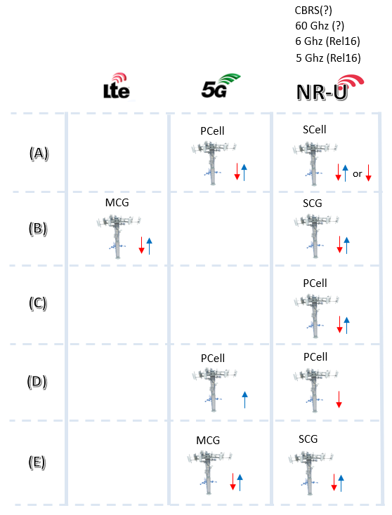
Figure 1. Row D is the one to look at twice. Both of its boxes are labelled PCell, so the pair is a single cell rather than two, with the downlink in the unlicensed band and the uplink in the licensed band.
- The grid has three columns, LTE, 5G and NR-U, and five rows lettered A to E down the left side.
- Row A pairs a 5G PCell carrying both directions with an NR-U SCell, and the SCell is annotated as DL plus UL or DL only.
- Row B is the only row with anything in the LTE column. LTE holds the master cell group and NR-U holds the secondary cell group.
- Row C has a single box, in the NR-U column, marked PCell. The other two columns are empty.
- Row D draws a 5G PCell with the blue uplink arrow only, beside an NR-U PCell with the red downlink arrow only.
- Row E repeats the master and secondary split of row B, with 5G rather than LTE in the master position.
- The NR-U column heading lists CBRS, 60 GHz, 6 GHz Release 16 and 5 GHz Release 16, and the first two carry question marks.
Four of the five keep an anchor in licensed spectrum : only scenario C removes it, so everything that has to be reliable moves onto the contended carrier with it.Scenario D is one cell, not two : the picture labels both boxes PCell, and the split is between directions rather than between cells.The anchor decides the core network : scenario B anchors on LTE and connects to the EPC, and every other scenario connects to the 5G core.Downlink only is a legitimate configuration : scenario A allows the NR-U SCell to carry no uplink at all, and that removes the UE side of the contention problem.
PHY layer consideration
RP-201834 descirbes many aspects of Physical Layer aspects. Followings are what I think is important to notice. (NOTE : I haven't confirmed yet on whether all of these are specified in Release 16 TS document)
- Multiple DL to UL and UL to DL switching points in frame structure for LBT(Listen Before Talk)
- Scheduling multiple TTI for PUSCH
- Data Multiplexing considering LBT and channel access priorities
- LBT subbands within the wideband carrier. For all wide-band operation cases, CCA is performed in units of 20MHz (at least for 5GHz)
- NR-U Discovery Reference Signal (DRS)
- Block-interlaced transmission for PUCCH, PUSCH
- Support of Multiple PDSCH starting point
Listen before talk, as 37.213 writes it
Listen before talk sounds like one procedure, and it is four. 37.213 separates them by how long the sensing lasts, and by whether that length is random. The choice between them is not free. Each type is tied to what the transmission carries, and to whether somebody else has already won the channel.
Type 1 is the full procedure, and the only one with a random component. The transmitter senses the channel across a defer duration. It then draws a counter uniformly between zero and the current contention window, and decrements that counter one sensing slot at a time. Transmission may start once the counter reaches zero. A busy slot suspends the count rather than resetting it, so the waiting already done is not thrown away.
The three Type 2 variants are deterministic. Type 2A senses for a fixed interval built from two sensing slots. Type 2B senses within a shorter fixed duration, with the sensing slot placed at the end of it. Type 2C senses nothing at all, and pays for that with a hard limit on how long the transmission may last.
Type 2C looks like a loophole, and it is not. 37.213 clause 4.1.3 allows it only inside a channel occupancy that the other end already won, and only after a short gap. The reasoning behind all three variants is the same. Once a gNB or a UE has taken the channel, its partner may join without contending again, because the channel is already held.
Figure 2. The four types are drawn against a common start of transmission, so the length of the sensing that precedes it is what separates them. Only the Type 1 row contains a random quantity.
- Type 1 is drawn as a defer duration followed by a run of sensing slots, and the number of those slots is the random counter.
- Type 2A and Type 2B are drawn as fixed blocks, so the transmitter knows before it starts how long it will wait.
- Type 2C has a dashed empty block, because no sensing happens there at all.
- The Type 2C transmission block is labelled as capped, and that cap is what replaces the sensing.
Channel access priority classes
Type 1 needs two numbers before it can run. One is how long the defer duration is, and the other is how wide the contention window may grow. Both come from the channel access priority class of the traffic being sent, and 37.213 defines four of them in Table 4.1.1-1.
Priority class p |
mp |
CWmin,p |
CWmax,p |
Maximum channel occupancy |
Allowed CWp values |
1 |
1 |
3 |
7 |
2 ms |
3, 7 |
2 |
1 |
7 |
15 |
3 ms |
7, 15 |
3 |
3 |
15 |
63 |
8 or 10 ms |
15, 31, 63 |
4 |
7 |
15 |
1023 |
8 or 10 ms |
15, 31, 63, 127, 255, 511, 1023 |
mp is the number of consecutive sensing slots inside the defer duration. The second column is therefore the fixed part of the wait, and the two contention window columns bound the random part. Two things follow from the rest of the table. Higher priority buys a shorter wait, because class 1 draws its counter from a window of at most seven slots while class 4 may reach 1023. Higher priority also buys a shorter turn, because class 1 has to stop after 2 ms while classes 3 and 4 hold the channel for 8 or 10 ms.
The contention window is not fixed inside a class. It moves with how the previous transmission went. 37.213 clause 4.1.4.2 resets the window to its minimum when at least one HARQ-ACK for the reference duration came back as ACK. For code block group feedback the threshold is 10 percent of the reports. When neither condition holds, the window is increased to the next higher allowed value. That is what the last column of the table is for, because the window only ever takes one of those listed values.
Everything above is the dynamic procedure, where the transmitter contends whenever it has something to send. 37.213 clause 4.3 defines a second mode, called semi-static channel occupancy. The channel is taken in fixed periods there, and each period ends with an idle duration that the gNB must leave empty. A network configured that way does not run the random backoff of Type 1 at all.
Only Type 1 is random : the three Type 2 variants sense for a fixed time or not at all. They exist for transmissions that join an occupancy the other end already won.Priority class sets both the wait and the turn : class 1 waits the least and stops after 2 ms. Class 4 may wait through 1023 slots, and it holds the channel for 8 or 10 ms.HARQ-ACK drives the contention window : one ACK in the reference duration resets it to the minimum, and no ACK pushes it up to the next allowed value.Backoff is not the only mode : clause 4.3 builds the occupancy from fixed periods with a mandatory idle gap, and that mode does not contend at all.
Presentations on YouTube
The ten talks below were recorded across several years, so they do not all describe the same specification. The earlier ones argue for unlicensed operation as an idea and predate Release 16. The later ones compare a finished NR-U against Wi-Fi 6. That comparison is the one worth watching first.
[1] Webinar - Fixed 5G: From mmWave to NR-U
[2] 5G NR-U and WiFi
[3] The license-exempt spectrum: An opportunity for 3GPP
[4] Sivers IMA On-Demand Webinar: Fixed Wireless Access (FWA), Licensed or Unlicensed 5G
[5] TWS 2015: Role of Unlicensed Spectrum in 5G
[6] Fixed Broadband LTE in Unlicensed 5 GHz Spectrum with Telrad Webinar
[7] NEWSDR 2019 Technical Presentation 2: 5G NR-U "Houston, we have a problem here
[8] 5G NR-U vs WiFi6 video Part 1
[9] 5G NR-U vs WiFi6 - Part 2 |5G | NR-U | WiFi6 | WiFI |
[10] TWS 2015: Role of Unlicensed Spectrum in 5G
Reference :
[1] How does support for unlicensed spectrum with NR-U transform what 5G can do for you? (Qualcomm)
[2] Unlicensed Use of the 6 GHz Band (FCC)
[3] FCC Opens Spectrum Horizons for New Services & Technologies (FCC)
[4] FCC Modernizes 5.9 GHz Band to Improve Wi-Fi and Automotive Safety (FCC)
[5] List of WLAN channels (Wikipedia)