For the general description of PTRS, I would just quote the explanation from VI-B of this paper since it is better described than I would have done.
PTRS is used for tracking the phase of the local oscillator at the receiver and transmitter. This enables
- Time Domain Symbol Location
- Frequency Domain RB and Subcarrier Location of PDSCH PTRS
- RRC Parameters for PDSCH PTRS
- Reference
Time Domain Symbol Location
Time domain symbol location of PDSCH PTRS is specified by 38.211 7.4.1.2.2 and following is my interpretation. Two things have to be settled before a symbol index can be written down. The first is how far apart the PT-RS symbols sit. The second is where the count starts from, and that turns out not to be the start of the allocation.
PT-RS is dense in time and sparse in frequency, which is the reverse of most reference signals. Phase noise is the reason. It changes fast enough that the correction has to be repeated several times inside one slot. It is also common to the whole carrier, so one subcarrier every few resource blocks is enough to measure it.
38.211 writes the symbol positions as a five step loop rather than as a formula. The loop starts at a reference symbol and steps forward by L_PT-RS symbols each time. The two steps worth reading twice are the ones inside the test, because they move the reference to a DM-RS symbol whenever the next interval would overlap one.
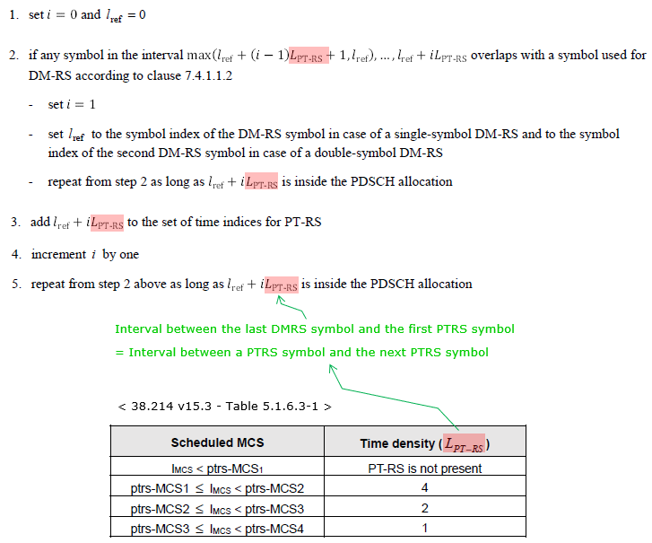
Figure 1. DM-RS is the point the count restarts from. The interval from the last DM-RS symbol to the first PT-RS symbol is therefore the same as the interval between two PT-RS symbols.
The same rule is easier to see on a grid than in the loop. Figure 2 places one DM-RS symbol and the PT-RS symbols that follow it across one allocation.
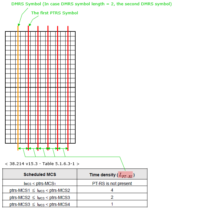
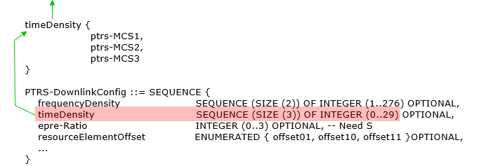
Figure 3. timeDensity carries three MCS thresholds rather than a density. The density follows once those thresholds place the scheduled MCS in a row of the table.
Dense in time, sparse in frequency : phase noise changes quickly and is common to the carrier, so the sampling has to be frequent but not wide.DM-RS is the reset point : the interval restarts from a DM-RS symbol whenever the next PT-RS symbol would land on one.The spacing is one number : L_PT-RS, read from 38.214 Table 5.1.6.3-1 against the scheduled MCS.The RRC field carries thresholds : timeDensity holds ptrs-MCS1 to ptrs-MCS3, and the density is looked up rather than signalled.Below the first threshold there is no PT-RS : an MCS under ptrs-MCS1 means the signal is not present at all.
Frequency Domain RB and Subcarrier Location of PDSCH PTRS
Frequency domain symbol location of PDSCH PTRS is specified by 38.211 7.4.1.2.2 and following is my interpretation. The answer is one subcarrier index, and it has to hold for every resource block the signal occupies. Reaching it needs a density, an offset derived from the RNTI, and a table indexed by the DM-RS port.
The frequency question has two halves, and they are answered by different parameters. The first is how far apart the PT-RS subcarriers sit, which is a whole number of resource blocks. The second is which subcarrier inside the resource block carries it, which depends on the DM-RS port and on one RRC field.
The spacing comes first, because it is the simpler of the two. Adjacent PT-RS subcarriers are K_PT-RS resource blocks apart, so the signal never shifts position inside a resource block from one occurrence to the next.
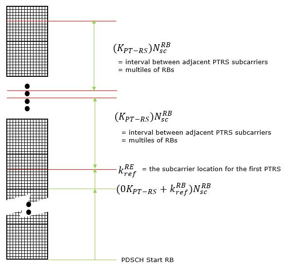
Figure 4. Only the first PT-RS subcarrier has to be computed. Everything after it is a fixed step of K_PT-RS resource blocks, which is why the spacing costs no signalling.
The first position is where the work is. It is built from three terms, and Figure 5 gives the formula together with the two tables that supply them.
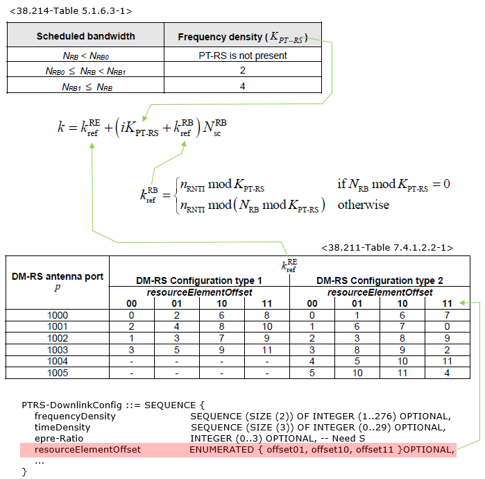
Figure 5. The offset is derived from the RNTI, so two devices scheduled on the same resource blocks do not land on the same subcarrier. Separating them costs no extra signalling, because both ends already know the RNTI.
One label in the picture needs correcting. The frequency density table is 38.214 Table 5.1.6.3-2, and Table 5.1.6.3-1 is the time density table used in the section above. The two tables live in the same clause and are easy to swap.
The last term is the one a log will disagree with. The value of k_ref^RE is read from 38.211 Table 7.4.1.2.2-1 against the DM-RS antenna port and the configured resourceElementOffset. When resourceElementOffset is not configured, the column for offset00 applies, and that column is not drawn in the picture.
Two densities, two tables : K_PT-RS from the scheduled bandwidth, and L_PT-RS from the scheduled MCS.The spacing is in resource blocks : K_PT-RS times N_sc^RB, so PT-RS holds the same subcarrier index in every resource block it occupies.The RNTI decides the offset : k_ref^RB is derived from n_RNTI, which keeps two devices on the same allocation off the same subcarrier.The DM-RS port decides the subcarrier : k_ref^RE comes from 38.211 Table 7.4.1.2.2-1, indexed by the DM-RS port and resourceElementOffset.Absent means offset00 : with resourceElementOffset not configured, the offset00 column of that table applies.
RRC Parameters for PDSCH PTRS
Three information elements carry the configuration and they nest, which is why the parameter is hard to find from its name alone. PDSCH-Config points at DMRS-DownlinkConfig, and DMRS-DownlinkConfig points at PTRS-DownlinkConfig. Only the last of the three is about PT-RS, and the two above it are shown because the path to it is not obvious.
Following is based on
PDSCH-Config ::=                        SEQUENCE {
    dataScramblingIdentityPDSCH             INTEGER (0..1023)                                                   OPTIONAL,   -- Need S
    dmrs-DownlinkForPDSCH-MappingTypeA      SetupRelease { DMRS-DownlinkConfig }                                OPTIONAL,   -- Need M
    dmrs-DownlinkForPDSCH-MappingTypeB      SetupRelease { DMRS-DownlinkConfig }                                OPTIONAL,   -- Need M

    tci-StatesToAddModList                  SEQUENCE (SIZE(1..maxNrofTCI-States)) OF TCI-State                  OPTIONAL,   -- Need N
    tci-StatesToReleaseList                 SEQUENCE (SIZE(1..maxNrofTCI-States)) OF TCI-StateId                OPTIONAL,   -- Need N
    vrb-ToPRB-Interleaver                   ENUMERATED {n2, n4}                                                 OPTIONAL,   -- Need S
    resourceAllocation                      ENUMERATED { resourceAllocationType0, resourceAllocationType1, dynamicSwitch},
    pdsch-TimeDomainAllocationList          SetupRelease { PDSCH-TimeDomainResourceAllocationList }             OPTIONAL,   -- Need M
    pdsch-AggregationFactor                 ENUMERATED { n2, n4, n8 }                                           OPTIONAL,   -- Need S
    rateMatchPatternToAddModList            SEQUENCE (SIZE (1..maxNrofRateMatchPatterns)) OF RateMatchPattern   OPTIONAL,   -- Need N
    rateMatchPatternToReleaseList           SEQUENCE (SIZE (1..maxNrofRateMatchPatterns)) OF RateMatchPatternId OPTIONAL,   -- Need N
    rateMatchPatternGroup1                  RateMatchPatternGroup                                               OPTIONAL,   -- Need R
    rateMatchPatternGroup2                  RateMatchPatternGroup                                               OPTIONAL,   -- Need R

    rbg-Size                                ENUMERATED {config1, config2},
    mcs-Table                               ENUMERATED {qam256, qam64LowSE}                                     OPTIONAL,   -- Need S
    maxNrofCodeWordsScheduledByDCI          ENUMERATED {n1, n2}                                                 OPTIONAL,   -- Need R

    prb-BundlingType                        CHOICE {
        staticBundling                          SEQUENCE {
            bundleSize                              ENUMERATED { n4, wideband }                                 OPTIONAL    -- Need S
        },
        dynamicBundling                     SEQUENCE {
            bundleSizeSet1                      ENUMERATED { n4, wideband, n2-wideband, n4-wideband }           OPTIONAL,   -- Need S
            bundleSizeSet2                      ENUMERATED { n4, wideband }                                     OPTIONAL    -- Need S
        }
    },
    zp-CSI-RS-ResourceToAddModList                  SEQUENCE (SIZE (1..maxNrofZP-CSI-RS-Resources)) OF ZP-CSI-RS-Resource
                                                                                                                OPTIONAL,   -- Need N
    zp-CSI-RS-ResourceToReleaseList                 SEQUENCE (SIZE (1..maxNrofZP-CSI-RS-Resources)) OF ZP-CSI-RS-ResourceId
                                                                                                                OPTIONAL,   -- Need N
    aperiodic-ZP-CSI-RS-ResourceSetsToAddModList    SEQUENCE (SIZE (1..maxNrofZP-CSI-RS-ResourceSets)) OF ZP-CSI-RS-ResourceSet
                                                                                                                OPTIONAL,   -- Need N
    aperiodic-ZP-CSI-RS-ResourceSetsToReleaseList SEQUENCE (SIZE (1..maxNrofZP-CSI-RS-ResourceSets)) OF ZP-CSI-RS-ResourceSetId
                                                                                                                OPTIONAL,   -- Need N
    sp-ZP-CSI-RS-ResourceSetsToAddModList   SEQUENCE (SIZE (1..maxNrofZP-CSI-RS-ResourceSets)) OF ZP-CSI-RS-ResourceSet
                                                                                                                OPTIONAL,   -- Need N
    sp-ZP-CSI-RS-ResourceSetsToReleaseList  SEQUENCE (SIZE (1..maxNrofZP-CSI-RS-ResourceSets)) OF ZP-CSI-RS-ResourceSetId
                                                                                                                OPTIONAL,   -- Need N
    p-ZP-CSI-RS-ResourceSet                 SetupRelease { ZP-CSI-RS-ResourceSet }
                                                                                                                OPTIONAL,   -- Need M
    ...
    -- the r16, r17, r18 and r19 extension groups are not PT-RS related and are not repeated here
}
The path continues through the downlink DM-RS configuration. The field phaseTrackingRS carries it, and it is the only line in DMRS-DownlinkConfig that concerns PT-RS.
Following is based on
DMRS-DownlinkConfig ::=             SEQUENCE {
    dmrs-Type                           ENUMERATED {type2}                                                      OPTIONAL,   -- Need S
    dmrs-AdditionalPosition             ENUMERATED {pos0, pos1, pos3}                                           OPTIONAL,   -- Need S
    maxLength                           ENUMERATED {len2}                                                       OPTIONAL,   -- Need S
    scramblingID0                       INTEGER (0..65535)                                                      OPTIONAL,   -- Need S
    scramblingID1                       INTEGER (0..65535)                                                      OPTIONAL,   -- Need S
    phaseTrackingRS                     SetupRelease { PTRS-DownlinkConfig  }                                   OPTIONAL,   -- Need M
    ...,
    [[
    dmrs-Downlink-r16               ENUMERATED {enabled}                                                        OPTIONAL    -- Need R
    ]],
    [[
    dmrs-TypeEnh-r18                ENUMERATED {enabled}                                                        OPTIONAL    -- Need R
    ]]
}
The last of the three holds the parameters this page is about. Four fields were there from Release 15, and Release 16 added one more that limits how many PT-RS ports the device has to support.
Following is based on
PTRS-DownlinkConfig ::=             SEQUENCE {
    frequencyDensity                    SEQUENCE (SIZE (2)) OF INTEGER (1..276)                                 OPTIONAL,   -- Need S
    timeDensity                         SEQUENCE (SIZE (3)) OF INTEGER (0..29)                                  OPTIONAL,   -- Need S
    epre-Ratio                          INTEGER (0..3)                                                          OPTIONAL,   -- Need S
    resourceElementOffset               ENUMERATED { offset01, offset10, offset11 }                             OPTIONAL,   -- Need S
    ...,
    [[
    maxNrofPorts-r16                    ENUMERATED {n1, n2}                                                     OPTIONAL    -- Need R
    ]]

}
Reference
[1] 38.211 v19.4.0 : NR - Physical channels and modulation. Clause 7.4.1.2.2 gives the PT-RS mapping for PDSCH, and Table 7.4.1.2.2-1 gives k_ref^RE per DM-RS antenna port.
[2] 38.214 v19.4.0 : NR - Physical layer procedures for data. Clause 5.1.6.3 holds Table 5.1.6.3-1 for time density and Table 5.1.6.3-2 for frequency density.
[3] 38.331 v19.3.0 : NR - Radio Resource Control (RRC) protocol specification. PDSCH-Config, DMRS-DownlinkConfig and PTRS-DownlinkConfig are quoted from it.
[4] arXiv 1806.06898 : A Primer on 3GPP New Radio. Section VI-B is quoted in the opening of this page.