5G/NR - Pre Trial - Physical Signal - PSS
NOTE : This note is about a tempary 5G specification that was implemented and tried before 5G specification is finalized. I keep this note for study purpose.
Once the UE has found the PSS, it knows the symbol timing and NID(2), but not much more. The SSS is the next signal it reads. Like the PSS, the Pre-Trial SSS takes its sequence from LTE and repeats it in all 14 symbols of subframes 0 and 25. If you have read the PSS page, the layout of this page will look familiar.
SSS is a specific physical layer signal that is used for radio frame synchronization. It has characterstics as listed below.
- Mapped to 72 active sub carriers, located above the PSS at every OFDM symbols in Subframe 0 and at every OFDM symbols in Subframe 25. (Note : the 5 subcarriers at the bottom and top (10 subcarriers in total) are not allocated any data, meaning only 62 subcarriers carries the real SSS data)
- Made up of 62 Gold Sequence Values
- Used for Downlink Frame Synchronization
- One of the critical factors determining Physical Cell ID
The sections that follow cover these points in order. The first builds the sequence, the second places it on the resource grid, and the third compares the result with the LTE SSS and the NR SSS.
Baseband Signal Generation
The signal generation algorithm of Pretrial SSS is same as LTE SSS. It generate 504 different Gold sequences that are made up of 62 data points as shown below. This is same as LTE SSS signal generation. 504 different Gold Sequence is distictively generated by the two parameter NID(1) and NID(2). NID(1) can be any value from 0 through 167. NID(2) can be 0 or 1 or 2.
The construction has more steps than the PSS, so let's go through it once. The SSS is built from three length-31 m-sequences, which the code calls s_tilda, c_tilda and z_tilda. Each one comes from a 5-bit shift register that starts at 0 0 0 0 1. Each bit is then mapped to +1 or -1, so every SSS value is +1 or -1.
NID(1) selects two cyclic shifts of s_tilda, called m0 and m1. NID(2), which the UE already knows from the PSS, selects the cyclic shift of c_tilda. The c_tilda term scrambles the sequence, and the z_tilda term adds a second scrambling on the odd elements. The even and odd elements are then interleaved into 62 values.
The two subframes do not carry the same SSS. In subframe 0, the even elements use s_tilda shifted by m0, and the odd elements use it shifted by m1. In subframe 25, the two shifts swap places. This swap matters, because the PSS is identical in subframes 0 and 25. So the PSS alone cannot tell the UE which half of the radio frame it found, but the SSS can.
There are 168 values of NID(1) and 3 values of NID(2), so each subframe has 504 possible sequences. All 1008 sequences across the two subframes are different. One SSS detection therefore gives the UE both NID(1) and the half frame. The UE then combines NID(1) with NID(2) into the Physical Cell ID, NIDcell = 3NID(1) + NID(2), as in LTE.
One example of SSS sequence is shown below.
|
NID |
Sequence Plot |
|
NID1 = 0 NID2 = 0 |
|

The example uses NID1 = 0 and NID2 = 0, which gives m0 = 0 and m1 = 1. The small panels on the left are constellations, and every value lands on -1 or +1 on the real axis. The wide panels plot the 62 values in order, for subframe 0 on top and subframe 25 underneath.
Compare the two wide panels. The first six values are the same in both rows. After those six, the two rows no longer match. That difference comes from the swap of m0 and m1 between the two subframes. A UE that correlates against both versions can tell subframe 0 from subframe 25 by which version gives the peak.
Disclaimer : This code is just to push myself (probably readers) to look into the algorithm (formula) specified in the specification to the most detailed level. If you try to convert the specification into the programming code whatever language you choose, you will understand the equation / algorithm in much more detailed level than just reading the document. However, this code has not been verified with any real data.
|
Filename : Generate_Sss.m Last Update : Dec 16, 2016 |
|
%V5G.211 - 6.8.2.1 function SequenceSss = Generate_Sss(SSS)
NID1 = SSS.NID1; NID2 = SSS.NID2; SUBFRAME = SSS.SubFrame;
q_prime = floor(NID1/30); q = floor(((NID1+q_prime*(q_prime+1)/2))/30); m_prime = NID1 + q *(q+1)/2; m0 = mod(m_prime, 31); m1 = mod(m0 + floor(m_prime/31)+1,31);
%%%%%%%%%%%%%%%%% generate d_even() sequence %%%%%%%%%%%%%%%% % Generate the sequence x_s() : x() for calculating s_tilda() x_s = zeros(1,31); x_s(1:5) = [0 0 0 0 1];
for i = 0:25 x_s((i+5)+1) = mod(x_s(i+2+1)+x_s(i+1),2); end;
% Generate the sequence x_c() : x() for calculating c_tilda() x_c = zeros(1,31); x_c(1:5) = [0 0 0 0 1];
for i = 0:25 x_c((i+5)+1) = mod(x_c(i+3+1)+x_c(i+1),2); end;
% Generate the sequence s_tilda() s_tilda = zeros(1,31); for i = 0:30 s_tilda(i+1) = 1 - 2*x_s(i+1); end;
% Generate the sequence c_tilda() c_tilda = zeros(1,31); for i = 0:30 c_tilda(i+1) = 1 - 2*x_c(i+1); end;
% Generate s0_m0_even() s0_m0_even = zeros(1,31); for n = 0:30 s0_m0_even(n+1) = s_tilda(mod(n+m0,31)+1); end;
% Generate s1_m1_even() s1_m1_even = zeros(1,31); for n = 0:30 s1_m1_even(n+1) = s_tilda(mod(n+m1,31)+1); end;
% Generate c0_even() c0_even = zeros(1,31); for n = 0:30 c0_even(n+1) = c_tilda(mod(n+NID2,31)+1); end;
% Calculate d_even_sub0 d_even_sub0 = s0_m0_even .* c0_even;
% Calculate d_even_sub25 d_even_sub25 = s1_m1_even .* c0_even;
%%%%%%%%%%%%%%%%% generate d_odd() sequence %%%%%%%%%%%%%%%% % Generate the sequence x_s() : x() for calculating s_tilda() x_z = zeros(1,31); x_z(1:5) = [0 0 0 0 1];
for i = 0:25 x_z((i+5)+1) = mod(x_z(i+4+1) + x_z(i+2+1) + x_z(i+1+1)+ x_z(i+1),2); end;
% Generate the sequence z_tilda() z_tilda = zeros(1,31); for i = 0:30 z_tilda(i+1) = 1 - 2*x_z(i+1); end;
% Generate s1_m1_odd() s1_m1_odd = zeros(1,31); for n = 0:30 s1_m1_odd(n+1) = s_tilda(mod(n+m1,31)+1); end;
% Generate s0_m0_odd() s0_m0_odd = zeros(1,31); for n = 0:30 s0_m0_odd(n+1) = s_tilda(mod(n+m0,31)+1); end;
% Generate c1_odd() c1_odd = zeros(1,31); for n = 0:30 c1_odd(n+1) = c_tilda(mod(n+NID2+3,31)+1); end;
% Generate z1_m0_odd() z1_m0_odd = zeros(1,31); for n = 0:30 z1_m0_odd(n+1) = z_tilda(mod(n+mod(m0,8),31)+1); end;
% Generate z1_m1_odd() z1_m1_odd = zeros(1,31); for n = 0:30 z1_m1_odd(n+1) = z_tilda(mod(n+mod(m1,8),31)+1); end;
% Calculate d_odd_sub0 d_odd_sub0 = s1_m1_odd .* c1_odd .* z1_m0_odd;
% Calculate d_odd_sub25 d_odd_sub25 = s0_m0_odd .* c1_odd .* z1_m1_odd;
% Calculate d_sub0 SequenceSss.Subframe0 = zeros(1,62); SequenceSss.Subframe0(1:2:end-1) = d_even_sub0; SequenceSss.Subframe0(2:2:end) = d_odd_sub0;
% Calculate d_sub25 SequenceSss.Subframe25 = zeros(1,62); SequenceSss.Subframe25(1:2:end-1) = d_even_sub25; SequenceSss.Subframe25(2:2:end) = d_odd_sub25;
end |
|
Filename : PlotSequence_Sss.m Last Update : Dec 16, 2016 |
|
function h=PlotSequence_Sss(SssSequence,PlotOption)
xmin = PlotOption.xmin; xmax = PlotOption.xmax; ymin = PlotOption.ymin; ymax = PlotOption.ymax;
subplot(2,5,1); plot(real(SssSequence.Subframe0),imag(SssSequence.Subframe0), ... 'ro','MarkerFaceColor',[1 0 1]); axis([xmin xmax ymin ymax]); subplot(2,5,[2 5]); plot(real(SssSequence.Subframe0),'ro-');xlim([0 length(SssSequence.Subframe0)]); title('Subframe 0');
subplot(2,5,6); plot(real(SssSequence.Subframe25),imag(SssSequence.Subframe25), ... 'ro','MarkerFaceColor',[1 0 1]); axis([xmin xmax ymin ymax]); subplot(2,5,[7 10]); plot(real(SssSequence.Subframe25),'ro-');xlim([0 length(SssSequence.Subframe25)]); title('Subframe 25');
end |
|
Filename : Test_Generation_Sss.m Last Update : Dec 16, 2016 |
|
SSS.NID1 = 0; SSS.NID2 = 0; SSS.SubFrame = 25;
SssSequence = Generate_Sss(SSS);
PlotOption.xmin = -1.5; PlotOption.xmax = 1.5; PlotOption.ymin = -1.5; PlotOption.ymax = 1.5;
PlotSequence_Sss(SssSequence,PlotOption);
|
Generate_Sss.m builds both sequences in one call and returns them as SequenceSss.Subframe0 and SequenceSss.Subframe25. The SubFrame field in Test_Generation_Sss.m is read into SUBFRAME, but Generate_Sss.m never uses it. So the plot always shows both subframes, whatever SubFrame is set to.
The Pre-Trial SSS reuses the LTE sequence : three length-31 m-sequences give 62 interleaved values of +1 or -1.NID(1) selects the shifts m0 and m1 : NID(2) from the PSS selects the scrambling shift.Subframes 0 and 25 carry different sequences : m0 and m1 swap places, so the SSS tells the UE which half of the frame it found.Each subframe has 504 sequences : one for each combination of 168 NID(1) values and 3 NID(2) values.
RE Mapping of SSS
RE Mapping, or Resource Element Mapping, decides which subcarrier and which OFDM symbol carries each SSS value. In time the SSS follows the same pattern as the PSS. So the part to watch here is its position in frequency, right next to the PSS.
The location of SSS within a radio frame is as highlighed in red box below. It is at the center of the frequency domain in subframe 0 and 25.

In the radio frame map, each column is one of the 50 subframes, numbered 0 to 49, and the vertical axis is frequency. The red boxes appear only in subframes 0 and 25, directly above the yellow PSS block. So the SSS shares its two subframes with the PSS, and the UE gets one SSS opportunity every 5 ms.
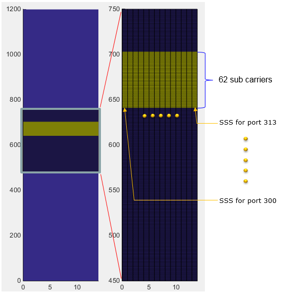
If you cut out only subframe 0 and maginify the resource elements above PSS, it looks as shown below. In case of LTE SSS, it occupies only one OFDM symbol but in 5G Pretrial it occupies the whole subframe (i.e, 14 OFDM Symbols). Why it use 14 OFDM symbols ? Actually, the data being carried by each OFDM symbol is same in every symbol. The difference is with antenna ports. As you see below, each of OFDM symbol for SSS is mapped to different antenna ports. These antenna ports will use different Beam Configuration.
In short, the same SSS signal is being transmitted in every symbols in subframe 0 and 25 with different beam direction for each symbol. (If you are interested in the fundamental idea of this type of transmission, refer to Synchronization Signal in a frame structure).
Matlab Code : SSS
The left panel of the magnified view shows the whole subframe, with subcarriers 0 to 1200 on the vertical axis. The right panel enlarges subcarriers 450 to 750. There the SSS fills the 62 subcarriers from about 640 to 700, in every one of the 14 OFDM symbols. The PSS sits lower, around subcarrier 600, so the SSS lies just above it.
The labels mark the SSS for port 300 on the first symbol and the SSS for port 313 on the last symbol. These are the same ports that carry the PSS in the same symbols. So in each symbol, the UE can estimate the channel from the PSS and use that estimate to detect the SSS coherently.
This layout is the reverse of LTE. In LTE, the SSS uses the same subcarriers as the PSS, in the OFDM symbol before it. In the Pre-Trial, the SSS uses the same symbols as the PSS, on different subcarriers. The SSS also repeats in all 14 symbols, so it gives no symbol index either. The ESS still has to supply that.
The SSS sits directly above the PSS : both use 62 subcarriers near the center of the band, in subframes 0 and 25.The SSS fills all 14 symbols : one antenna port per symbol, from port 300 to port 313, the same as the PSS.The PSS and the SSS share a port in each symbol : the UE can use the PSS as a channel reference for the SSS.The SSS gives the half frame, not the symbol : the ESS still has to supply the symbol index.
Comparison with LTE SSS and NR SSS
The Pre-Trial SSS keeps the LTE sequence, but it places the signal in a new way. NR later changed both the sequence and its job. Let's put the three side by side, so you can see what each design asks the SSS to do.
|
Item |
LTE SSS |
5G Pre-Trial SSS |
NR SSS |
|
Sequence |
Two interleaved length-31 m-sequences, scrambled |
Same as LTE |
Product of two length-127 m-sequences |
|
Number of values |
62 |
62 |
127 |
|
Range of NID(1) |
0 to 167 |
0 to 167 |
0 to 335 |
|
Number of cell IDs |
504 |
504 |
1008 |
|
Differs between half frames |
Yes, subframe 0 and subframe 5 |
Yes, subframe 0 and subframe 25 |
No, the same sequence in every SSB |
|
Position relative to PSS |
Same subcarriers, one OFDM symbol before the PSS for FDD |
Same OFDM symbols, on subcarriers above the PSS |
Same subcarriers, two OFDM symbols after the PSS |
|
Position in time |
One OFDM symbol, in subframes 0 and 5 |
All 14 OFDM symbols of subframes 0 and 25 |
The third OFDM symbol of each SSB |
|
How the UE learns the half frame |
SSS |
SSS |
PBCH payload |
Start with the sequence rows. The Pre-Trial kept the LTE SSS unchanged, so it also kept 168 values of NID(1) and 504 cell IDs. NR moved to a length-127 sequence built from two m-sequences. With the longer sequence, NR doubled the range of NID(1) and reached 1008 cell IDs.
Now look at the half frame row. LTE and the Pre-Trial both ask the SSS to mark the half frame, which is why their SSS differs between the two synchronization subframes. NR removed that job from the SSS. Every NR SSB carries the same SSS, and the UE reads the half frame from the PBCH payload instead.
The position rows show the last difference. LTE separates the PSS and the SSS in time. The Pre-Trial separates them in frequency, so that both fit into each beam symbol. NR returned to separation in time, inside one SSB. For the NR side in detail, see NR SSS.
The Pre-Trial kept the LTE sequence : 62 values, 168 values of NID(1) and 504 cell IDs.NR replaced the sequence : a length-127 sequence supports 336 values of NID(1) and 1008 cell IDs.NR took the half frame job away from the SSS : the PBCH payload carries it instead.The Pre-Trial separates PSS and SSS in frequency : LTE and NR separate them in time.