Overall Architecture of NR RAN (Radio Access Network) would not look much different from LTE RAN Architecture. However getting into details, you would start seeing some differences as well. You see different name of each node and interface. MME/S-GW in LTE is replaced by AMF/UPF in NR and X2/S1 in LTE are replaced by Xn/NG-C/U in NR. Different name would mean different protocol and implementation. Among all of these differences, out of the most outstanding one would be that the gNB internal structure is split into two parts called CU (Central Unit) and DU (Distributed Unit) as shown below and these two entities are connected by a new interface called F1 (For the details of F1 interface, refer to 38.473).
Put the two generations side by side and the resemblance is the first thing you notice. Same triangle of base stations, same dashed lines going up to the core, same solid line running between neighbours. Only the labels have changed.

That similarity is real but it is also the last thing on this page that will be simple. The interesting change is not in the names. It is that the base station itself stopped being one box.
- Where to split between CU and DU ?
- The Eight Split Options
- Why the Split ?
- Where the Industry Landed
- DU and RU : the Lower Layer Split
- How RUs Are Actually Built
- RU, TRP and Cell : Three Different Things
- CU-CP, CU-UP and E1
- Any Concerns on the Split ?
- Reference
The magnified panel on the right of the figure below is the part that matters. From the outside a gNB still looks like one node, and Xn still runs between neighbours as though nothing had changed. Open one up and there is a CU with two DUs hanging off it on separate F1 links.
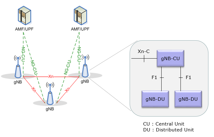
Notice that the split is invisible from outside the gNB. Xn and NG terminate on the gNB as a whole. A neighbouring base station has no idea whether it is talking to one box or to a CU with a dozen DUs behind it. That is deliberate, and it is why the split could be introduced without changing any of the interfaces around it.
Where to split between CU and DU ?
My first question when I heard of this split was 'exactly at which point the split happens ?'. For now, it seems to be dependent on how you implement it. Theoretically you can split at every layers in the protocol stack. You will find the detailed descriptions about the details on all the possible split options in TR 38.801 - 11.1.1,11.1.2, but it seems that the most common and agreeable split line seems to be as shown below.
So the split line lands between PDCP and RLC, as drawn below. Everything from PDCP upward lives in the CU, and RLC, MAC and PHY stay down in the DU.
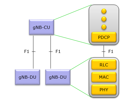
One consequence is worth pulling out of that picture. RLC is in the DU, so the entire ARQ and HARQ machinery stays local to the radio. Nothing that has to respond within a slot has to cross F1, which is exactly why F1 tolerates a long fibre run.
Then you may have this question. Why this option (i.e, splitting between RLC and PDCP) is preferred (at least preferred at the time of writing, May 2018) ? it is justified in TR 38.801 as follows :
- This option will allow traffic aggregation from NR and E-UTRA transmission points to be centralized. Additionally, it can facilitate the management of traffic load between NR and E-UTRA transmission points.
- Fundamentals for achieving a PDCP-RLC split have already been standardized for LTE Dual Connectivity, alternative 3C. Therefore this split option should be the most straightforward option to standardize and the incremental effort required to standardize it should be relatively small
The Eight Split Options
The specification quoted above defines eight of these, and the page so far has only named one of them. They are worth seeing together, because the list is really a single idea repeated. Pick a boundary in the protocol stack and cut there.
The numbering runs top down. Option 1 cuts near the top of the stack, option 8 cuts at the very bottom, just above the radio itself.
Option |
Cut between |
Notes |
1 |
RRC and PDCP |
Only the control plane brain is centralised. Very little to gain, and it went nowhere. |
The one drawn in the figure above, and the one 3GPP standardised as F1. Also the one that already had a precedent, since LTE dual connectivity split at the same place. |
||
3 |
Inside RLC |
High RLC in the CU, low RLC in the DU. Segmentation ends up on one side and ARQ on the other. |
4 |
RLC and MAC |
Attracted little interest. The interface would carry MAC SDUs while HARQ timing still has to be met across it. |
5 |
Inside MAC |
Scheduling in the CU, HARQ in the DU. The idea is that scheduling across many cells can then be coordinated centrally. |
6 |
MAC and PHY |
Transport blocks cross the link. Bandwidth still tracks traffic, but the latency budget is now inside a slot. |
Several sub-variants, 7-1, 7-2 and 7-3, differing in how much of the physical layer stays at the radio. This is where the second real split ended up, and it is covered further down the page. |
||
8 |
PHY and RF |
Nothing but the radio at the far end, fed with time domain samples. This is what CPRI carries, and that page works out why it stops being possible once you have sixty four antennas. |
One axis explains the whole table, and it runs in both directions at once. The further down you cut, the more of the base station becomes centralised software, and the more brutal the link between the two halves has to be.
Split |
What crosses the link |
Bandwidth behaviour |
Latency budget |
Option 2, F1 |
PDCP PDUs, which is user data |
Tracks actual traffic. An idle cell costs almost nothing. |
Milliseconds. Tens of kilometres of fibre is fine. |
Option 6 |
Transport blocks |
Still tracks traffic |
Sub-millisecond, because HARQ now sits across the cut |
Frequency domain IQ, after precoding |
Scales with bandwidth and layers, not with users |
Around a hundred microseconds |
|
Option 8 |
Time domain IQ, the raw waveform |
Fixed by the radio configuration alone. Traffic is irrelevant. |
Tens of microseconds |
Exact numbers depend on which reference configuration you assume, so treat the last two columns as orders of magnitude rather than requirements. The shape is what matters, and the shape is that these two columns pull against each other.
Why the Split ?
Then a next question would be 'Why we need to think of this kind of split ?'. I think the simple answer would be 'it is because this split helps to virtualize the network functionalities'. Virtualization usually mean flexibility and cost reduction. With this kind of split, we can think of a RAN implementation as illustrated below. At least as of now, it would be difficult to virtualize the lower layer of gNB(PHY/MAC/RLC), but you would be able to put higher layer protocol stack (PDCP and above) into a open hardware and software-based protocol stack.
The figure below is what that looks like when you draw it as equipment rather than as protocol layers. A general purpose server running the upper stack, a switch, and a set of DUs on the end of it.
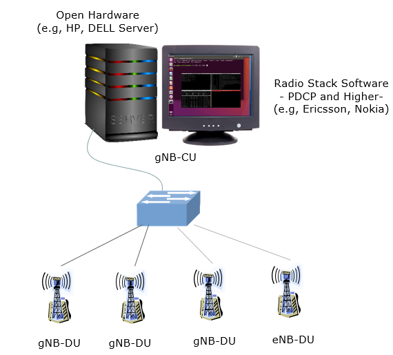
The fourth tower in that picture is labelled eNB-DU rather than gNB-DU, and it is not a typo. Once the upper stack is software on a server, there is no strong reason it cannot terminate LTE and NR at the same time. That is the traffic aggregation argument quoted from the specification above.
Where the Industry Landed
This page was first written in May 2018, and it says so. I think the prediction above turned out right, and also incomplete, so here is what happened next.
Option 2 did win, and it became F1 in 38.401 and 38.473. That much the page already says. What it could not know is that a second split would arrive from somewhere else entirely. A real base station ended up in three pieces rather than two.
The second cut is inside the physical layer, between what O-RAN calls the DU and the RU. It uses a variant of option 7-2 known as 7-2x. Frequency domain samples cross it, after precoding, which is what keeps the bandwidth from scaling with antenna count the way option 8 does.
Two things about this are worth being clear on, because the two splits are often discussed as though they were the same project.
They came from different bodies . F1 is 3GPP. Open Fronthaul is O-RAN Alliance, which is an operator led group rather than a standards body in the same sense.They solve different problems . F1 exists to centralise the upper stack onto shared hardware. Open Fronthaul exists to break the vendor lock between a baseband unit and its radios. That link had been proprietary in all but name, even where CPRI was nominally the standard.
So the "Interoperability" line in the specification quotation above, and the interoperability caveat that CPRI never quite delivered on, are the same complaint arriving twenty years apart. Open Fronthaul is the second attempt at it.
DU and RU : the Lower Layer Split
The section above introduced this one in a sentence. It deserves more than that, because it is a different kind of split from F1 and most of the difficulty in a modern RAN deployment lives here.
The difference in one line. F1 cuts between two protocol layers, so what crosses it is packets. The lower layer split cuts
Reading left to right, the O-DU takes a transport block from MAC and works down through coding, modulation and layer mapping. The O-RU takes over somewhere near the end and finishes the job into an antenna. Where exactly it takes over is the whole question.
O-RAN defines two answers, and they are not two levels of sophistication. They are two different places to put the precoder.
O-RU |
Precoding happens in |
What this means for the link |
The O-DU |
The O-DU sends data already mapped onto antenna ports, so the fronthaul carries one stream per port. Simple radio, and fine while the port count is small. |
|
The O-RU |
The O-DU sends one stream per layer, plus beamforming weights or a beam identifier, and the radio applies them. The fronthaul now scales with layers rather than with antennas, which is the only reason massive MIMO fits down a fibre at all. |
That last row is the thing worth remembering. A sixty four antenna radio running four layers sends four streams across the fronthaul, not sixty four.
How much does it actually save ?
Worth putting numbers on, because the saving is larger than it looks and it comes from three separate places at once. Take a 100 MHz NR carrier at 30 kHz spacing, so 273 resource blocks, on a radio with 32 antennas driving 4 layers.
Option 8, time domain |
Option 7-2x, frequency domain |
|
What crosses the link |
Time domain samples, one stream per antenna |
Frequency domain samples, one stream per layer |
Samples per second |
122.88 M, the full sampling rate including guard band and cyclic prefix |
91.7 M, being 3,276 occupied subcarriers across 28,000 symbols per second |
Bits per sample |
30, being 15 each for I and Q |
18, being a 9 bit mantissa each with block floating point |
Streams |
32 antennas |
4 layers |
Three savings multiplying together, none of them individually dramatic.
Frequency domain means only the occupied subcarriers travel, and the cyclic prefix is added at the radio rather than carried to it. That is a factor of about 0.75.Compression at a 9 bit mantissa instead of 15 bits is a factor of 0.6.Per layer instead of per antenna , four against thirty two, is a factor of 0.125.
Multiply them and you get 0.056, which is about eighteen times less traffic. That is the difference between a link nobody can build and one that fits comfortably inside 25 Gbit/s Ethernet.
Change the assumptions and the numbers move. Compression ratios vary, layer counts vary, and an uplink budget is not the same as a downlink one. The shape does not move. Two of those three savings are unavailable to option 8 no matter how you configure it. That is the point the CPRI note arrives at from the other direction.
Four planes, not one pipe
CPRI was a single synchronous bit stream that carried everything at once. Open Fronthaul is Ethernet, and Ethernet carries nothing you do not explicitly send. So the one pipe became four separate things.
Plane |
Carries |
Notes |
Scheduling and beamforming commands |
Sent ahead of the data it describes, telling the radio what is coming and which beam to put it on. |
|
The IQ samples |
Essentially all of the bandwidth, and the thing the table above is about. |
|
Timing |
PTP and SyncE, using the G.8275.1 telecom profile. This one has no equivalent in CPRI, and the reason is below. |
|
M-plane |
Management |
NETCONF and YANG. Configuration, software, alarms. |
The S-plane is the one that surprises people, so it is worth dwelling on. A CPRI link delivered timing for free, because the radio simply recovered its clock from the incoming bit stream. There was nothing to configure and nothing to go wrong.
Ethernet is not synchronous. The moment fronthaul moved onto it, the clock had to be put back by hand, and that is what the S-plane is. A grandmaster somewhere, PTP messages across the network, and every switch in the path having to be aware of the timing rather than merely forwarding frames.
I would say that is where most of the operational pain of open fronthaul actually lives. The radio and the DU can both be perfectly conformant. The link will still not work if the switch between them was bought as an ordinary switch.
What it runs over
The transport underneath all of this is eCPRI, carried in Ethernet frames or over UDP/IP. The name is unfortunate, since it suggests a newer version of CPRI, and it is not one. It shares an ancestor and very little else.
Two consequences follow from being packet based, and both are gains that cost something.
- Fronthaul can now share a network. Several radios over one link, statistical multiplexing, ordinary switches in the path. None of that was possible with a dedicated synchronous fibre per radio.
- Latency and jitter are now yours to manage rather than a property of the medium. The budget is roughly a hundred microseconds one way, set by HARQ timing, and a packet network only meets that if it was designed to.
It is also worth knowing that the O-RAN split and the 3GPP split options are not the same document. Option 7-2x is O-RAN's refinement of a variant 3GPP had described but never fully specified, which is why the notation is so awkward.
How RUs Are Actually Built
Everything above treats the RU as a single kind of box, and it is not. The word covers equipment that differs by a factor of thirty in transmit chains, and by an order of magnitude in power draw. Quite often it differs in whether it speaks the interface this page has been describing at all.
Worth separating out the axes, because they vary independently and a real product is a choice on each one.
By shape
The most visible difference is where the radio sits relative to the antenna.
Type |
Typical size |
What it looks like on site |
|
2T2R to 8T8R |
A box bolted to the tower with a passive antenna above it, joined by RF jumpers. The traditional arrangement, and still the normal one for low band FDD where the antenna is large and the chain count is small. |
|
32T32R, 64T64R |
Radio and antenna in one enclosure with no RF cabling between them. Once you have sixty four chains, cabling them individually stops being sensible, and the feeder loss disappears as a bonus. This is the mid band 5G workhorse. |
Integrated small cell |
2T2R, 4T4R |
DU and RU in the same box, on a wall or a pole. There is no fronthaul interface to speak of because there is no fronthaul, which quietly removes most of the difficulty in the previous section. |
mmWave unit |
Large element counts |
A panel where the array and the radio are inseparable. Beamforming is analogue or hybrid rather than fully digital, which changes what can sensibly cross the fronthaul. |
By what is inside
Two units of the same shape can still be very different products.
Axis |
The choice, and what it costs |
Category A or Category B, as in the section above. This is the single largest architectural difference between two O-RUs, and it decides how much of the physical layer the radio has to implement. |
|
Digital gives every element its own transceiver chain and the most freedom, at the highest power. Analogue drives a phase shifter network from one chain, which is cheap but can only point one beam at a time. Hybrid sits between them, and mmWave has little choice about using it. |
|
Silicon |
Early O-RUs leaned heavily on FPGA, which is flexible and thirsty. Purpose built radio SoCs have since arrived and are the reason O-RU power figures have come down as much as they have. |
Duplex and band |
An FDD unit needs a duplex filter per chain and transmits continuously. A TDD unit switches, which is what makes several of the sleep modes on the energy page possible at all. Multi band units combine what used to be separate boxes. |
This is the one that decides whether the word O-RU applies. A unit speaking eCPRI with the four planes is an O-RU. A unit speaking CPRI is a perfectly good radio unit and not an O-RU at all. |
That last row is worth stating plainly, because the vocabulary blurs it.
Why the RU is the part that matters
One more reason to care about how these are built. The RU is where the site's energy goes.
The energy note works through the figures. The short version is that the radio unit accounts for the large majority of base station equipment power. The RAN in turn accounts for most of the network total. Decisions taken in the RU therefore dominate the energy behaviour of everything else.
It is also the only part of the chain you cannot move. A CU can go to a data centre and a DU can go to a cabinet at the bottom of the tower. The RU has to be where the antenna is, in weather, on a mast, with whatever power and cooling can be got to it.
RU, TRP and Cell : Three Different Things
Short answer to the obvious question. No, an RU is not a TRP, and the two are not even the same kind of noun.
An RU is a piece of equipment. A TRP is a place the network transmits from, as seen from the radio interface. A cell is neither, it is an identity the UE camps on. They line up often enough in a simple macro site that people stop distinguishing them, and then a deployment turns up where they do not.
The figure shows the case that breaks the habit. Two radio units, two transmission points, and one cell across both of them. That is multi-TRP, and it is exactly the arrangement described on the CoMP note.
RU |
TRP |
Cell |
|
Whose word |
O-RAN, and the industry generally |
3GPP RAN1 |
3GPP, everywhere |
Kind of thing |
Hardware. Something you can drop. |
A transmission point, defined by where the signal comes from |
An identity, defined by PCI and an SSB |
No. Never. The UE has no concept of an RU. |
Indirectly. It sees TCI states and coresetPoolIndex values, not TRPs. |
Yes, completely. This is what it measures and camps on. |
|
Is it an architectural node ? |
In O-RAN, yes |
In 38.401, no. gNB, gNB-CU and gNB-DU are nodes. TRP is not on that list. |
Not a node, but a first class concept everywhere |
Counting |
One RU can host several sectors, and therefore several of the other two |
Several TRPs can share one cell, which is the whole point of multi-TRP |
A cell belongs to exactly one gNB-DU |
The row worth staring at is the third one. There is no TRP identifier in the RRC configuration a UE receives for ordinary scheduling. What it gets instead is
So the UE is not told there are two transmission points. It is told that some control channels belong to one pool and some to another, and that certain beams behave as a group. Two transmission points is the conclusion, not the message.
There is one place where a TRP does get a proper identity, and it is worth knowing about because it is the exception. Positioning gives TRPs real identifiers, exchanged between the RAN and the location server. Working out where a UE is means knowing precisely which points its measurements came from. Outside positioning, TRP stays an engineering word rather than a protocol one.
How they line up in practice
Some common arrangements, which may help more than the definitions do.
Ordinary macro sector : one RU, one TRP, one cell. Everything lines up, which is why the words get used interchangeably.Three sector site : three RUs, three TRPs, three cells and three PCIs. Still one to one, just three of them, and usually one gNB-DU behind all of it.Multi-TRP : two or more RUs, two or more TRPs, andone cell. The UE sees a single PCI and a single serving cell while its data arrives from two places at once.Multi-band RU : one RU, several cells. A single box on the mast serving three bands is three cells, three PCIs and three sets of everything, out of one piece of equipment.mmWave panel : the boundaries blur further, because a panel with analogue beamforming behaves like several transmission points that cannot be used at the same instant.
Read that list and the pattern is that the mapping is many to many in both directions. One RU can carry several cells, and one cell can span several RUs. Any sentence that treats the two as synonyms is only true of the first line.
CU-CP, CU-UP and E1
One more division happened inside the CU, and the diagram above already gives it away. The CU itself splits into a control plane part and a user plane part.
CU-CP holds RRC and the control plane half of PDCP. It terminates F1-C towards the DU and NG-C towards the AMF.CU-UP holds SDAP and the user plane half of PDCP. It terminates F1-U towards the DU and NG-U towards the UPF.E1 joins the two, and it is specified in 38.463.
The reason for this one is capacity rather than latency. Control plane load and user plane load do not grow together, and a network adding traffic needs more CU-UP without needing more CU-CP. Splitting them means each can be scaled on its own.
It also means one CU-CP can sit in front of several CU-UPs. That is how a user plane function gets placed near where traffic breaks out, while the control plane stays central.
Any Concerns on the Split ?
Looks fancy and sound good, but isn't there any concern about this kind of implementation ? For any new technology, we always see both 'hype' and 'concern'. Only time will tell you. Followings are some of the commonly raised concern that I see in various readings.
Performance Issue : Even though we see ever increasing performance of those open hardware (e.g, HP / DELL Server) in one side, we see ever increasing requirement of throughput and latency on the other side (i.e, throughput and latency requirement proposed in NR). The question is whether the speed of the open hardware evolution is fast enough to catch up the speed of the requirement evolution.Ownership of Troubles : In deploying this kind of split architecture, it is highly likely that the hardware (i.e, server) and software (protocol stack) comes from different vendors. Then an important question (concern) would come out. Who is going to be responsible if some problem happens ? Of course, you would see some obvious hardware problems and some obvious software problems, but in reality there are a lot of problem sitting at the borderline between software and hardware(i.e, it is hard to clearly point out the root cause). As everyone can understand, nobody would like to take responsibilities for troubles. You would go through a lot of ping-pongs among different stakeholders (i.e, Network Operators, Hardware vendor, software (protocol stack) vendors).Security Issues : I don't think I need to say much on this. Whenever we talk about 'open system and software based system', the first concern is about security.
Eight years later, which of these were real ?
The list above ends by saying that only time will tell. Enough time has passed now, so here is how I would score the three of them.
Concern |
Verdict |
What actually happened |
Performance |
Open hardware did keep up. But a general purpose CPU alone was not enough. Special hardware for the physical layer was added, either as a separate accelerator card or built into the processor. So the answer is yes, it works. The remaining question is how much that extra hardware costs, in price and in power. |
|
This was the most accurate concern on the list. The industry did not solve the problem of who is responsible when something breaks. Most operators avoided the problem instead. They buy equipment that supports open interfaces, but they buy all of it from one vendor. Dell'Oro expects real multi-vendor RAN to stay under 5 percent of deployments even in 2030. |
||
Security |
Real, but for a different reason |
The problem is not that open systems are weaker by nature. The problem is that the specifications made too many security features optional. Germany's BSI and the EU wrote separate assessments and reached the same conclusion. O-RAN is not secure by default, and the open fronthaul adds the most new attack surface. |
The middle row is the important one. That concern was never really a technical question. It is about who takes responsibility when something does not work, and a specification cannot decide that.
The problems that were not on the 2018 list
Three more problems appeared that are not on the original list. Two of them are probably bigger than any of the original three.
Energy : this is the largest omission, and it is not mentioned anywhere in the 2018 list. A purpose built baseband unit was designed to fit a fixed power budget. A server with an accelerator card was not, and it draws almost the same power whether the cells are busy or idle. The energy note covers the ground in detail. The shape of the problem is that disaggregation adds a fixed overhead to a system whose traffic is anything but fixed.The RIC did not develop as promised : the near real time controller and its xApps were a main selling point of the whole idea. Very little has been built on them. Attention and money moved to the non real time side instead, the SMO and its rApps. The timing requirements there are much easier, and the benefit is easier to show. One forecast puts rApps and SMO at six times the size of the xApp market by 2027.Someone has to do the integration, and it is not free : a multi-vendor RAN needs one company responsible for making the parts work together. That job turned out to be expensive. In many deployments the company that took it on was one of the traditional vendors. That is an odd result for a movement that wanted to reduce the power of those same vendors.
There is a fourth problem, which this page has already described without calling it a concern. Moving fronthaul onto Ethernet meant putting timing back by hand. A conformant radio and a conformant DU will still not work together across a switch that was not chosen with the S-plane in mind.
My own view
The engineering was never the doubtful part. F1 and 7-2x are both finished, both deployed, and nobody argues about them now. If the question is whether a base station can be split into three parts and still work, the answer came years ago.
What was promised too strongly was the commercial result. The argument was that opening the interfaces would create a competitive market for each part. That has not happened yet. Open interfaces are necessary, but they are not enough on their own.
I think the reason is that a specification can define an interface, but it cannot decide who takes the risk. Two boxes can both pass conformance testing and still not work together. Someone has to be responsible when that happens. Operators big enough to do their own integration have done well with open RAN. Operators who wanted to buy a finished network, rather than build one, have mostly bought it from a single vendor, open interfaces included.
The original list also deserves some credit. It chose responsibility as a concern at a time when most articles were writing about cost savings. That is the concern that turned out to matter.
To be fair, it is still early. Open RAN revenue grew again in 2025 after two bad years. A small share of a very large market is still a large amount of equipment. The 2018 concerns asked whether this could be made to work at all. That question is settled. The argument now is about who pays to make it work well.
Reference
[1] 5G NR gNB Logical Architecture and Its Functional Split Options
[2] vRAN Tech Hits Resistance at SK Telecom
[3] Open RAN Grows in 2025 - Dell'Oro Group
[4] Energy measurement in open RAN, what the data shows - RCR Wireless
[5] Open RAN xApps look stillborn - Light Reading
[6] Report on the Cybersecurity of Open RAN - EU NIS Cooperation Group
[7] Open RAN Security Report - Quad Critical and Emerging Technology Working Group