NR RLC is almost same as LTE RLC. So if you are already faimiliar with LTE RLC, you wouldn't need much of extra study to understand NR RLC. If you are new to overall functionality of RLC, I would suggest you to go through LTE RLC page first. Since I wouldn't see any NR test equipment and UE in near future, I wouldn't be able to put much of practical information on NR RLC until the equipment and UE are available. Your knowledge on LTE RLC would help you understand NR RLC.
Actually a large portions of the contents on this page comes from the direct copy of LTE RLC page and I would try to highlight those parts which is unique to NR RLC.
- Overview / Overall Functionality
- TM Mode / Procedure
- Example 1 : BCCH System Information Delivery
- Example 2 : PCCH Paging Delivery
- Example 3 : CCCH Initial Access Message
- UM Mode / Procedure
- Example 1 : Downlink DTCH SDU Without Segmentation
- Example 2 : Uplink DTCH SDU With Segmentation
- Example 3 : Segmented UM SDU With a Missing Segment
- AM Mode / Procedure
- Example 1 : Downlink DCCH SDU With Successful ACK
- Example 2 : Downlink AMD PDU Loss and RLC Retransmission
- Example 3 : Uplink DTCH SDU With Segmentation and ACK
- Example 4 : Segment Level NACK and Retransmission
- Example 5 : Polling and T-PollRetransmit
- Example 6 : Duplicate AMD PDU After Retransmission
- RLC Data Structure
- TMD Data Structure
- UMD Data Structure
- Example 1 : Complete UMD PDU Without SN
- Example 2 : First Segment With 6 Bit SN
- Example 3 : Middle Segment With 6 Bit SN and SO
- Example 4 : Last Segment With 12 Bit SN and SO
- AMD Data Structure
- Example 1 : AMD PDU With 12 Bit SN and Complete SDU
- Example 2 : AMD PDU With 12 Bit SN, First Segment and Poll
- Example 3 : AMD PDU With 12 Bit SN and SO
- Example 4 : AMD PDU With 18 Bit SN and Complete SDU
- Example 5 : AMD PDU With 18 Bit SN and SO
- STATUS PDU
- RRC Parameters defining RLC
- Reference
Overview / Overall Functionality
As in LTE and WCDMA, NR RLC has three different mode : TM(Transparent Mode), UM(Unacknowledge Mode) and AM(Acknowledge mode). The details of each of these mode will be described later, but the very brief summary of key features of these mode is as follows :
- TM : No RLC Header, Buffering at Tx only, No Segmentation/Reassembly, No feedback (i.e, No ACK/NACK)
- UM : RLC Header, Buffering at both Tx and Rx, Segmentation/Reassembly, No feedback(i.e, No ACK/NACK)
- AM : RLC Header, Buffering at both Tx and Rx, Segmentation/Reassembly, Feedback(i.e, ACK/NACK)
Each of these mode can both transmit and receive data. In TM and UM, separate entity is used for transmission and reception, but in AM a single RLC entity perform both transmission and reception as illustrated below.
One important thing you need to pay attention to is that each of logical channels use a specific RLC mode as shown below.
- BCCH, PCCH, CCCH use RLC TM only.
- DCCH use RLC AM only.
- DTCH use RLC UM or AM. (Which mode is used for each DTCH channel ? This is determined by RRC message).

The three modes are not three settings of one algorithm. Each one adds a specific piece of machinery, and each piece has a cost. TM adds nothing, so it costs nothing and guarantees nothing. UM adds a sequence number and a reassembly timer. That gives ordered delivery of the segments that arrive, but a PDU that never arrives is still lost. AM adds a retransmission buffer, a polling mechanism and the STATUS PDU. That gives lossless delivery, at a cost in memory and in delay.
The mapping between logical channel and RLC mode is fixed rather than configurable, and the reason is in the channels themselves. BCCH, PCCH and CCCH are used before an RRC connection exists. There is no peer entity to send an ACK back, so TM is the only mode that works there. DCCH carries RRC signalling, where one lost message breaks the procedure. AM is therefore the only acceptable mode on DCCH. DTCH is the single channel with a real choice, and RRC makes that choice per bearer.
One consequence matters for the rest of this page. An RLC header in a log is not decodable on its own. The SN length, the mode and the timers all come from the RRC configuration. So a capture cannot be parsed past the start of the SN field without its RLC-BearerConfig.
NR RLC drops two functions that LTE RLC performed, and this is the part that is unique to NR. The first is concatenation. In NR the transport block is assembled by MAC, so RLC builds a PDU only once the grant size is already known. That is why the RLC header has an SI field and no length indicator. The second is in-sequence delivery. NR RLC reassembles a segmented SDU, but it does not hold a completed SDU back while an earlier one is still missing. 38.300 lists reordering and in-order delivery under PDCP rather than under RLC. So a gap in the RLC SN does not by itself stall the bearer.
The RLC mode follows the logical channel, not the traffic : BCCH, PCCH and CCCH always use TM, DCCH always uses AM, and only DTCH is configurable between UM and AM.The three modes differ by what they add : TM adds no header, UM adds SN and reassembly, and AM adds retransmission, polling and the STATUS PDU.AM uses one entity for both directions : TM and UM use a separate transmitting entity and receiving entity. A single AM entity both transmits and receives, so that it can carry ACK and NACK for the same bearer.Segmentation exists only in UM and AM : TM forwards whatever it holds, so an SDU larger than the granted transport block is discarded rather than split.NR RLC neither concatenates nor reorders : MAC assembles the transport block and PDCP performs reordering, so a gap in the RLC sequence number does not hold back the SDUs that did arrive.
Now let's look into a little bit further details on how data is processed by each RLC Mode. Since each RLC mode is associated with a specific set logical channels, I would suggest you to associate this RLC mode procedure to RLC layer processing mechanism for each of those channels.
TM Mode / Procedure
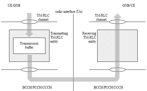
As you see in the following illustration. TM mode would mean 'almost no processing to RLC data'. The only thing it does is to buffer data on Tx side. There is no RLC header, No reordering, no segmentation, no reassembly is happening in this layer. Because of this 'no data processing' nature of TM mode, if you compare the RLC input and RLC output data of TM mode, you would see no difference between the two.
One important thing to keep in mind is that you need to pay attention to MAC/PHY resource allocation. Even if MAC/PHY resource is allocated smaller than the RLC packet, the RLC wouldn't care. It would just forward whatever it has to MAC/PHY. So those RLC data bigger than MAC/PHY resource may be chopped off or discarded.
Again another this to be noticed is that the local channel BCCH / PCCH / CCCH data is processed by this RLC mode.
< 38.322 - Figure 4.2.1.1.1-1: Model of two transparent mode peer entities >
Example 1 : BCCH System Information Delivery
In this example, the gNB sends system information over BCCH. From RLC point of view, the upper layer already provides a complete BCCH message. RLC TM does not add any RLC header and does not split the message. It buffers the SDU on the transmit side and forwards the same byte sequence to MAC as a TMD PDU.
|
# |
Node |
RLC packet |
comment |
|---|---|---|---|
|
1 |
gNB |
BCCH SDU from RRC |
RRC provides one complete broadcast message to RLC TM. |
|
2 |
gNB |
TMD PDU = BCCH SDU |
RLC TM makes a transparent PDU. No RLC header, SN, SI or SO field is added. |
|
3 |
gNB |
TMD PDU to MAC |
RLC forwards the complete payload to MAC. RLC does not resize it to fit a MAC grant. |
|
4 |
UE |
TMD PDU from MAC at UE |
The receiving RLC TM entity gets the payload from lower layer. |
|
5 |
UE |
BCCH SDU to RRC |
RLC delivers the same byte sequence upward as the BCCH SDU. |
Step 1 : The RRC layer at the gNB creates a BCCH SDU. For RLC, this is just an upper layer packet to be delivered transparently.
Step 2 : RLC TM maps the BCCH SDU to one TMD PDU. Since TM has no RLC header, the TMD PDU data field is the BCCH SDU itself.
Step 3 : The TMD PDU is passed to MAC. If the lower layer resource is not suitable for the full payload, RLC TM does not perform segmentation to solve it.
Step 4 : On the UE side, RLC TM receives the TMD PDU from MAC. There is no RLC sequence number to check and no reordering operation.
Step 5 : RLC TM delivers the received payload to RRC as a BCCH SDU. Ideally, this SDU is identical to the SDU created at the gNB side.
Example 2 : PCCH Paging Delivery
In this example, the network sends a paging message over PCCH. Paging is a good example of why TM is simple: the network wants to broadcast a small control message at a paging occasion, and RLC does not need retransmission, polling or status reporting. If the UE misses the paging occasion, RLC TM itself does not recover it.
|
# |
Node |
RLC packet |
comment |
|---|---|---|---|
|
1 |
gNB |
PCCH SDU from RRC |
The paging message is submitted to the RLC TM entity. |
|
2 |
gNB |
TMD PDU = PCCH SDU |
The paging payload is carried without an RLC header or sequence number. |
|
3 |
gNB |
TMD PDU to MAC |
MAC and PHY handle paging occasion timing and radio transmission. |
|
4 |
UE |
TMD PDU from MAC at UE |
If received, the UE RLC TM entity accepts the payload as-is. |
|
5 |
UE |
PCCH SDU to RRC |
RLC passes the paging message to RRC without any RLC-level feedback. |
Step 1 : The network RRC layer generates a PCCH SDU containing the paging information.
Step 2 : RLC TM creates a TMD PDU that contains only the PCCH SDU. There is no RLC header, so there is no RLC sequence number for later retransmission or duplicate detection.
Step 3 : RLC forwards the TMD PDU to MAC. The paging occasion, PDCCH monitoring and physical transmission are controlled below RLC.
Step 4 : If the UE successfully receives the transmission, MAC passes the payload to RLC TM. RLC TM does not perform reassembly or reordering.
Step 5 : RLC TM delivers the PCCH SDU to RRC. If the paging was missed, RLC TM does not send a NACK or trigger retransmission.
Example 3 : CCCH Initial Access Message
In this example, the UE sends an initial RRC message over CCCH, such as an RRCSetupRequest on SRB0. The UE does not yet have a normal dedicated signaling bearer using RLC AM, so CCCH uses RLC TM. The RLC operation is still the same: one complete CCCH SDU is passed through as one TMD PDU.
|
# |
Node |
RLC packet |
comment |
|---|---|---|---|
|
1 |
UE |
CCCH SDU from RRC |
UE RRC creates an initial access message for SRB0. |
|
2 |
UE |
TMD PDU = CCCH SDU |
RLC TM sends the CCCH payload transparently, with no RLC header. |
|
3 |
UE |
TMD PDU to MAC |
MAC transmits the CCCH payload using the available uplink procedure and resource. |
|
4 |
gNB |
TMD PDU from MAC at gNB |
The gNB RLC TM entity receives the transparent payload from MAC. |
|
5 |
gNB |
CCCH SDU to RRC |
RLC delivers the received CCCH SDU to the gNB RRC layer. |
Step 1 : The UE RRC layer creates a CCCH SDU, for example an RRCSetupRequest before dedicated signaling radio bearers are established.
Step 2 : RLC TM maps the CCCH SDU directly to a TMD PDU. There is no RLC SN, no segmentation information and no retransmission buffer.
Step 3 : The TMD PDU is passed to MAC for uplink transmission. The handling of uplink grant, transport block size and HARQ belongs to MAC/PHY, not RLC TM.
Step 4 : At the gNB, MAC passes the received payload to RLC TM. Since no RLC header exists, there is no header removal step.
Step 5 : RLC TM delivers the payload to RRC as the CCCH SDU. If this message is lost, recovery is handled by the access/RRC procedure, not by RLC retransmission.
UM Mode / Procedure
Next, let's look into UM mode. UM stands for 'Unacknowledged Mode'. 'Unacknowledged Mode' means 'it does not require any reception response from the other party'. 'Reception response' simply mean 'ACK' or 'NACK' from the other party. (UM mode is similar to TM mode in that it does not require any ACK/NACK from the other party, but it is different from TM in that I has it's own header)
What is the difference between UM mode and TM mode we saw above ? It seems that UM mode is doing more operation than TM mode.
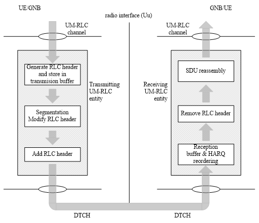
What kind of operation UM mode do ? You can just 'read' diagram for the answer. The answer would be a little bit different with transmitter side and reciever side.
Let's read the operation on transmitting side first. If you just read (verbalize) the diagram
i) Buffering the data and generate RLC Header.
ii) Segmetation (Split a big chunk into a multiple small chunk) and Modify RLC Header (Some field in RLC header should be changed based on the segmentation status)
iii) Add RLC header
From RAN2 NR#1:
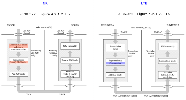
- Working assumption on no RLC concatenation taken at RAN2#96 is confirmed (i.e., concatenation of RLC PDUS is performed in MAC).
Then, read the operation on recieving side. If you just read (verbalize) the diagram
i) Buffering
ii) Reordering (Sometimes the chunks transmitted earlier from transmitter may arrive late at the reciever. In this case you have to reorder the incoming chunks into proper order for reassembly).
iii) Remove the RLC header (you would remember that the transmitter put the header to each of the chunk. So you have to remove this before you reassemble the data).
iv) Reassembly
< 38.322 - Figure 4.2.1.2.1-1: Model of two unacknowledged mode peer entities >
For those who already familiar with LTE RLC, I put the NR RLC UM and LTE RLC UM side by side for comparision. You see there is no difference in reciver side operation, but there is some difference in transmitter side. The most important difference in transmitter side is that NR RLC UM does not perform 'Concatenation' process.
Example 1 : Downlink DTCH SDU Without Segmentation
In this example, the gNB sends one DTCH SDU using UM mode and the SDU fits into the available lower layer resource. RLC UM still adds an RLC header, but it does not segment the SDU and it does not expect any RLC ACK/NACK from the UE.
|
# |
Node |
RLC packet |
comment |
|---|---|---|---|
|
1 |
gNB |
DTCH SDU from PDCP |
PDCP provides one complete user-plane SDU to the UM RLC entity. |
|
2 |
gNB |
UMD PDU, complete SDU |
RLC adds the UM header. Since the SDU is complete, no segmentation is done. |
|
3 |
gNB |
UMD PDU to MAC |
The complete UMD PDU is forwarded to MAC for downlink transmission. |
|
4 |
UE |
UMD PDU from MAC |
The UE RLC UM entity receives the PDU and removes the UM header. |
|
5 |
UE |
DTCH SDU to PDCP |
The recovered SDU is delivered upward. No RLC status report is sent. |
Step 1 : The gNB PDCP layer sends one DTCH SDU to RLC UM. This may be used for a bearer where low latency is more important than RLC retransmission.
Step 2 : RLC UM creates one UMD PDU and adds the UM header. For a complete SDU, the header indicates that the PDU contains the whole SDU.
Step 3 : RLC passes the UMD PDU to MAC. Unlike AM, no copy is kept in an RLC retransmission buffer for possible RLC-level retransmission.
Step 4 : The UE receives the UMD PDU from MAC and removes the RLC UM header. Since there was no segmentation, no reassembly operation is needed.
Step 5 : RLC UM delivers the DTCH SDU to PDCP. There is no RLC ACK/NACK or STATUS PDU in this procedure.
Example 2 : Uplink DTCH SDU With Segmentation
In this example, the UE sends a DTCH SDU that is too large for one available uplink transmission. RLC UM segments the SDU into multiple UMD PDUs, adds the proper UM headers, and the gNB RLC UM entity reassembles the original SDU after receiving all segments.
|
# |
Node |
RLC packet |
comment |
|---|---|---|---|
|
1 |
UE |
Large DTCH SDU from PDCP |
The SDU is stored in the UM transmit buffer before transmission. |
|
2 |
UE |
UMD PDU, first segment |
RLC creates the first segment and adds a UM header with segmentation information. |
|
3 |
UE |
UMD PDU, next segment |
Additional segment(s) carry the same SDU identity and offset information as needed. |
|
4 |
gNB |
First segment received |
The gNB buffers the segment because the full SDU is not complete yet. |
|
5 |
gNB |
Next segment received |
RLC uses the UM header information to place the segment at the proper position. |
|
6 |
gNB |
Reassembled DTCH SDU |
After all segments arrive, RLC removes headers and reconstructs the SDU. |
|
7 |
gNB |
DTCH SDU to PDCP |
The complete SDU is delivered upward without sending RLC feedback. |
Step 1 : The UE PDCP layer sends a DTCH SDU to RLC UM. The SDU is larger than what RLC can pass as one PDU for the current lower layer opportunity.
Step 2 : RLC UM creates the first segment. A segmented UMD PDU contains UM header information such as segmentation indication and sequence numbering.
Step 3 : RLC UM creates the next segment or segments. For segments after the first segment, offset information can be used so the receiver knows where that segment belongs in the original SDU.
Step 4 : The gNB RLC UM receiver gets the first segment and stores it in the receive buffer. It cannot deliver the SDU upward yet because the SDU is incomplete.
Step 5 : The gNB receives the remaining segment or segments. RLC UM uses the header fields to put the pieces in the correct order.
Step 6 : Once all required pieces are available, RLC removes the UM headers and reassembles the original DTCH SDU.
Step 7 : The reassembled SDU is delivered to PDCP. Even though segmentation and reassembly were used, no RLC ACK/NACK is generated.
Example 3 : Segmented UM SDU With a Missing Segment
In this example, the gNB sends a segmented DTCH SDU in UM mode, but one segment is not received by the UE. This shows the main limitation of UM mode: it can detect that reassembly is incomplete, but it does not request RLC retransmission from the peer entity.
|
# |
Node |
RLC packet |
comment |
|---|---|---|---|
|
1 |
gNB |
Large DTCH SDU from PDCP |
The gNB UM transmitter receives an SDU that will be segmented. |
|
2 |
gNB |
UMD PDU, first segment |
The first segment is transmitted to lower layer. |
|
3 |
gNB |
UMD PDU, last segment |
Another segment is transmitted, but one required segment is lost on the radio path. |
|
4 |
UE |
First segment received |
The UE buffers the received segment and waits for the missing piece. |
|
5 |
UE |
Incomplete reassembly |
RLC cannot reconstruct the SDU because one segment is missing. |
|
6 |
UE |
No RLC STATUS PDU |
The UE does not send an RLC NACK, and the incomplete SDU is not delivered to PDCP. |
Step 1 : The gNB PDCP layer submits a DTCH SDU to RLC UM, and the SDU needs to be split into multiple RLC PDUs.
Step 2 : RLC UM sends the first segment with a UM header that marks it as part of a segmented SDU.
Step 3 : RLC UM sends another segment, but at least one required segment is not received by the UE. MAC/PHY may perform HARQ below RLC, but RLC UM itself has no retransmission mechanism.
Step 4 : The UE receives one segment and stores it in the UM receive buffer. It cannot deliver the original SDU because all pieces are not available.
Step 5 : The receiver determines that reassembly cannot be completed, for example after the relevant reassembly handling expires or the missing part is no longer recoverable.
Step 6 : Since this is UM mode, the UE does not send an RLC STATUS PDU or NACK. The incomplete SDU is discarded or withheld from PDCP depending on the receiver state.
AM Mode / Procedure
Now let's look at AM mode which is the most complicated RLC type. 'AM' stands for 'Acknowledge Mode'. As it's name implies it requires ACK/NACK from the other party. It is more like TCP packet in IP world, whereas RLC UM is more like UDP in IP world.
Is it expecting the ACK/NACK for every transmission ? If it is the case, isn't it too much overhead ? Good question. Yes.. it is too much overhead. That's why we have RLC window concept (like TCP Window in IP traffic) and Polling bit concept and all sorts of ACK/NACK scheduling mechanism which makes it extremely difficult to understand full details of RLC AM operation. (This kind of detailed procedure would not be explained now.. but not sure by when I can get to the level of details -:)
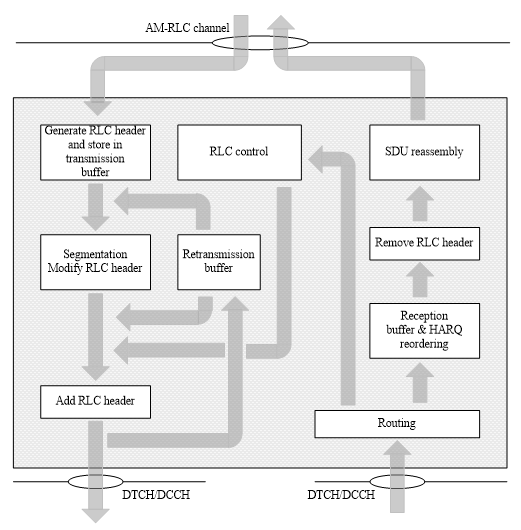
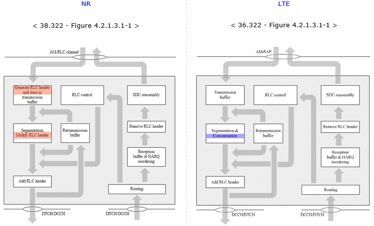
Now just look into the diagram from the specification. If you go through the left column and the right colum, you will see the same procedures you saw in UM mode. so I don't want to verbalize that part again. What is different from UM mode lies in the middle column, namely 'Retransmission buffer' and 'RLC control' procedure.
Let's just follow the arrrows. What is coming into the retransmission buffer ? i.e, what is the input to the retransmission buffer ?
After RLC transmitter do the segmentation/concatenation process, it adds RLC header and then it creates two identical copies and transmit the one copy of the data out to lower layer (MAC) and send another copy to Retransmission buffer.
If the RLC get Nack or does not get any response from the other party for a certain period of time, the RLC packet (we call this RLC PDU) in the retransmission buffer gets transmitted again. If the RLC get ACK, the ones in retransmission buffer would be discarded.
< 38.322 - Figure 4.2.1.3.1-1: Model of an acknowledged mode entity >
For those who already familiar with LTE RLC, I put the NR RLC AM and LTE RLC AM side by side for comparision. You see there is no difference in reciver side operation, but there is some difference in transmitter side. The most important difference in transmitter side is that NR RLC AM does not perform 'Concatenation' process.
Example 1 : Downlink DCCH SDU With Successful ACK
In this example, the gNB sends one DCCH SDU using AM mode and the UE receives it successfully. The important difference from UM mode is that the transmitting AM entity keeps a copy in the retransmission buffer until it receives positive status information from the peer RLC entity.
|
# |
Node |
RLC packet |
comment |
|---|---|---|---|
|
1 |
gNB |
DCCH SDU from PDCP |
A signaling SDU is submitted to the AM RLC transmitter. |
|
2 |
gNB |
AMD PDU SN = 10 |
RLC adds an AM header and assigns a sequence number. |
|
3 |
gNB |
SN = 10 in retransmission buffer |
A copy is kept until the peer confirms successful reception. |
|
4 |
UE |
AMD PDU SN = 10 received |
The UE receives the AMD PDU, removes the RLC header and recovers the SDU. |
|
5 |
UE |
DCCH SDU to PDCP |
The recovered signaling SDU is delivered upward. |
|
6 |
UE |
STATUS PDU ACK_SN = 11 |
When status reporting is triggered, the UE indicates that SN 10 has been received. |
|
7 |
gNB |
Discard buffered SN = 10 |
After the ACK information is received, the copy in the retransmission buffer is removed. |
Step 1 : The gNB receives one DCCH SDU from the upper layer. DCCH normally uses RLC AM because signaling usually needs reliable delivery.
Step 2 : RLC AM creates an AMD PDU and assigns sequence number 10. The SN is the basic reference used later by the receiver to acknowledge or negatively acknowledge the PDU.
Step 3 : The gNB keeps a copy of the AMD PDU in the retransmission buffer. This is the main AM behavior that does not exist in TM or UM.
Step 4 : The UE receives the AMD PDU from MAC, removes the RLC AM header and obtains the original SDU.
Step 5 : The UE RLC AM entity delivers the recovered DCCH SDU to PDCP.
Step 6 : The UE sends a STATUS PDU when status reporting is triggered, commonly by polling. ACK_SN = 11 means that all AMD PDUs up to but not including SN 11 are acknowledged, assuming no NACK field is present.
Step 7 : The gNB receives the status information and removes SN 10 from the retransmission buffer because it no longer needs to be protected by RLC retransmission.
Example 2 : Downlink AMD PDU Loss and RLC Retransmission
In this example, the gNB sends several AMD PDUs and one of them is not received by the UE. The receiver reports the missing sequence number in a STATUS PDU. The transmitter then retransmits the missing AMD PDU from its retransmission buffer.
|
# |
Node |
RLC packet |
comment |
|---|---|---|---|
|
1 |
gNB |
AMD PDU SN = 20 |
First PDU is transmitted and stored in the retransmission buffer. |
|
2 |
gNB |
AMD PDU SN = 21 |
Second PDU is transmitted, but it is lost before reaching the UE RLC entity. |
|
3 |
gNB |
AMD PDU SN = 22, P = 1 |
The poll bit asks the UE to return RLC status information. |
|
4 |
UE |
SN = 20 and SN = 22 received |
The UE detects a gap because SN 21 is missing. |
|
5 |
UE |
STATUS PDU NACK_SN = 21 |
The UE acknowledges what it has received and reports SN 21 as missing. |
|
6 |
gNB |
Retransmitted AMD PDU SN = 21 |
The gNB retransmits SN 21 from the retransmission buffer. |
|
7 |
UE |
SN = 21 received |
The missing PDU arrives, allowing the receiver to close the gap. |
|
8 |
UE |
SDUs delivered in order |
After the gap is filled, RLC can deliver the recovered SDUs upward. |
Step 1 : The gNB sends SN 20 and keeps a copy for possible retransmission.
Step 2 : The gNB sends SN 21, but the UE RLC entity does not receive it. This is the kind of error AM is designed to repair at the RLC layer.
Step 3 : The gNB sends SN 22 with the P bit set. The P bit requests a STATUS PDU from the peer AM entity.
Step 4 : The UE receives SN 20 and SN 22. Since SN 21 is missing, the UE knows that the sequence is not continuous.
Step 5 : The UE sends a STATUS PDU containing NACK_SN = 21. Depending on exact status content, the STATUS PDU may also carry ACK_SN and extension fields.
Step 6 : The gNB uses the retransmission buffer to send SN 21 again. This retransmission is an RLC AM function, separate from MAC HARQ.
Step 7 : The UE receives the retransmitted SN 21 and fills the receive-side gap.
Step 8 : Once the missing PDU is available, the UE can deliver the corresponding SDUs upward in the proper order.
Example 3 : Uplink DTCH SDU With Segmentation and ACK
In this example, the UE sends a large DTCH SDU using AM mode. The SDU is segmented into multiple AMD PDUs. The gNB reassembles the SDU and later acknowledges reception, which allows the UE to remove the transmitted segments from its retransmission buffer.
|
# |
Node |
RLC packet |
comment |
|---|---|---|---|
|
1 |
UE |
Large DTCH SDU from PDCP |
The SDU is too large to send as one AMD PDU. |
|
2 |
UE |
AMD PDU SN = 40, first segment |
RLC sends the first segment and keeps a buffered copy. |
|
3 |
UE |
AMD PDU SN = 40, last segment |
The later segment carries offset information for reassembly. |
|
4 |
gNB |
Segments for SN = 40 received |
The gNB buffers the received segments until the SDU is complete. |
|
5 |
gNB |
Reassembled DTCH SDU |
RLC removes AM headers and reconstructs the original SDU. |
|
6 |
gNB |
STATUS PDU ACK_SN = 41 |
The receiver acknowledges successful reception of SDU SN 40. |
|
7 |
UE |
Discard buffered SN = 40 |
The UE removes the acknowledged segment copies from its retransmission buffer. |
Step 1 : The UE receives a large DTCH SDU from PDCP. Since it cannot be sent as one suitable RLC PDU, AM segmentation is needed.
Step 2 : RLC AM sends the first segment. The sequence number identifies the SDU being segmented, and the segment is kept in the retransmission buffer.
Step 3 : RLC AM sends the last segment. Segment information and offset information allow the receiver to reconstruct the original SDU.
Step 4 : The gNB receives the segments and buffers them because the complete SDU is reconstructed only after all needed pieces are available.
Step 5 : After all segments of SN 40 are present, the gNB reassembles the SDU and delivers it to PDCP.
Step 6 : The gNB sends status information acknowledging reception up to SN 41.
Step 7 : The UE receives the ACK information and removes all buffered copies associated with SN 40.
Example 4 : Segment Level NACK and Retransmission
In this example, a large AMD SDU is segmented and only part of the SDU is lost. AM mode can report not only a missing sequence number, but also a missing byte range within a segmented SDU by using segment offset information in the STATUS PDU.
|
# |
Node |
RLC packet |
comment |
|---|---|---|---|
|
1 |
gNB |
AMD PDU SN = 50, SO = 0 |
The first byte range of the segmented SDU is sent. |
|
2 |
gNB |
AMD PDU SN = 50, middle segment |
This segment is lost before it reaches the UE RLC entity. |
|
3 |
gNB |
AMD PDU SN = 50, last segment |
The last segment arrives, but the SDU still has a hole in the middle. |
|
4 |
UE |
Incomplete SN = 50 |
The UE has enough information to identify the missing byte range. |
|
5 |
UE |
STATUS PDU NACK_SN = 50, SOstart/SOend |
The UE requests retransmission of only the missing segment range. |
|
6 |
gNB |
Retransmitted segment SN = 50 |
The gNB retransmits the requested segment from the retransmission buffer. |
|
7 |
UE |
Reassembled SDU SN = 50 |
After the missing byte range arrives, the UE reassembles and delivers the SDU. |
Step 1 : The gNB sends the first segment of SDU SN 50. Since this is AM, the transmitted segment is also stored for possible retransmission.
Step 2 : The middle segment is transmitted but lost before the UE RLC entity receives it.
Step 3 : The last segment is received. The UE can see that it has the beginning and ending parts, but not the whole SDU.
Step 4 : The UE marks SN 50 as incomplete and identifies the missing byte range by using segment offset information.
Step 5 : The UE sends a STATUS PDU with NACK_SN = 50 and segment offset fields such as SOstart and SOend. This is more precise than simply asking for the whole SDU again.
Step 6 : The gNB retransmits only the missing part from the retransmission buffer.
Step 7 : The UE receives the missing segment, completes reassembly and delivers the recovered SDU upward.
Example 5 : Polling and T-PollRetransmit
In this example, the transmitter requests status by setting the poll bit, but no STATUS PDU is received before the poll retransmission timer expires. This shows why AM mode has polling control in addition to normal data transmission and retransmission.
|
# |
Node |
RLC packet |
comment |
|---|---|---|---|
|
1 |
UE |
AMD PDU SN = 60, P = 1 |
The UE sends a polled PDU to request receiver status. |
|
2 |
gNB |
AMD PDU SN = 60 received |
The gNB receives the PDU and is expected to provide status when allowed. |
|
3 |
gNB |
STATUS PDU generated or delayed |
The STATUS PDU may be delayed by lower layer scheduling or lost on the air. |
|
4 |
UE |
T-PollRetransmit expires |
The transmitter still has no status response for the poll. |
|
5 |
UE |
AMD PDU with P = 1 again |
The UE sends another poll, using new data or a selected buffered PDU as applicable. |
|
6 |
gNB |
STATUS PDU returned |
The receiver reports ACK/NACK information to refresh the transmitter state. |
Step 1 : The UE sends an AMD PDU with the P bit set. This asks the peer AM entity to provide status information.
Step 2 : The gNB receives the polled AMD PDU. A receiving AM entity does not necessarily send status after every data PDU, but a poll is a direct request for status reporting.
Step 3 : The STATUS PDU may be delayed or may not reach the UE. From the UE transmitter point of view, the poll has not been answered yet.
Step 4 : T-PollRetransmit expires at the UE. This prevents the transmitter from waiting forever for status information.
Step 5 : The UE sends another AMD PDU with the poll bit set. Depending on buffer state, this may be new data or a suitable PDU from the retransmission buffer.
Step 6 : The gNB sends STATUS information. The UE can then update its retransmission buffer and decide whether anything must be retransmitted.
Example 6 : Duplicate AMD PDU After Retransmission
In this example, a PDU is retransmitted because it was reported missing, but the original copy arrives late as well. AM mode uses sequence numbers and receiver state to avoid delivering the same SDU twice.
|
# |
Node |
RLC packet |
comment |
|---|---|---|---|
|
1 |
gNB |
AMD PDU SN = 70 |
The original PDU is transmitted but arrives very late at the UE. |
|
2 |
UE |
STATUS PDU NACK_SN = 70 |
Before the late copy arrives, the UE reports SN 70 as missing. |
|
3 |
gNB |
Retransmitted AMD PDU SN = 70 |
The gNB retransmits SN 70 from the retransmission buffer. |
|
4 |
UE |
SN = 70 delivered |
The UE receives one valid copy and delivers the recovered SDU upward. |
|
5 |
UE |
Duplicate SN = 70 received |
The late original copy arrives after SN 70 has already been handled. |
|
6 |
UE |
Duplicate discarded |
RLC AM does not deliver the same SDU twice. |
Step 1 : The gNB transmits SN 70, but the PDU is delayed or not available to the UE RLC entity when status is generated.
Step 2 : The UE reports SN 70 as missing in a STATUS PDU.
Step 3 : The gNB receives the NACK and retransmits SN 70 from the retransmission buffer.
Step 4 : The UE receives one copy of SN 70 and delivers the corresponding SDU upward if it is complete and in order.
Step 5 : The delayed original copy later reaches the UE. From RLC AM point of view, this is now a duplicate PDU.
Step 6 : The UE discards the duplicate and does not deliver the same SDU again. This is why AM needs sequence number based receiver state in addition to retransmission.
RLC Data Structure
RLC data structure describes how the payload from upper layer is carried over the RLC interface for each operating mode. In TM, the structure is almost transparent and there is no RLC header. In UM, the RLC header carries information needed for sequence handling, segmentation and reassembly, but it does not support RLC retransmission. In AM, the header and STATUS PDU structure become more complicated because AM has to support ordered delivery, polling, ACK/NACK reporting, retransmission and segment-level recovery.
TMD Data Structure
TMD stands for Transparent Mode Data. This is the simplest RLC PDU structure because the RLC entity does not add any RLC header to the upper layer payload. The TMD PDU is essentially the RLC SDU itself, so there is no sequence number, no segmentation information, no polling bit and no retransmission related field in this structure.
< 38.322-Figure 6.2.2.2-1: TMD PDU >

UMD Data Structure
The UM header is not one fixed layout. Its length changes with what the PDU carries, because a complete SDU needs no sequence number and a non-first segment needs a byte offset as well. The SI field decides which of those fields are present. The configured SN length then decides how wide the SN field is.
There are various types of UMD PDU as illustrated below.
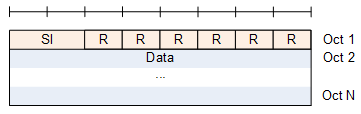
First type is the one shown below. The RLC header has only SI field and R field and has no SN field. 38.322-6.2.2.3 states "When an UMD PDU contains a complete RLC SDU, the UMD PDU header only contains the SI and R fields. An UMD PDU header contains the SN field only when the corresponding RLC SDU is segmented."
< 38.322-Figure 6.2.1.3-1: UMD PDU containing a complete RLC SDU >
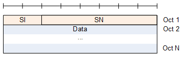
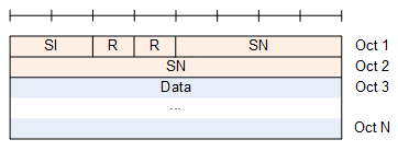
Second type is the ones shown below. This type carries SN field. The length of SN field is 6 or 12 bits. Which one to be used is determined by RRC Configuration SN-FieldLengthUM. This type does not carry SO (Segment Offset) field. 38.322-6.2.2.3 states "An UMD PDU carrying the first segment of an RLC SDU does not carry the SO field in its header."
< 38.322-Figure 6.2.2.3-2: UMD PDU with 6 bit SN (No SO) >
< 38.322-Figure 6.2.2.3-3: UMD PDU with 12 bit SN (No SO) >
Third type is the ones shown below. It carries SI,SN and SO. The existence of SO indicates that this PDU carries a segment of an SDU and the segment is NOT the first segment. (If it is the first segment, SO field would not be carried).
< 38.322-Figure 6.2.2.3-4: UMD PDU with 6 bit SN and with SO >
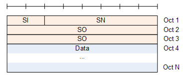
< 38.322-Figure 6.2.2.3-5: UMD PDU with 12 bit SN and with SO >

< 38.322-Table 6.2.2.4-1: SI field interpretation >

UMD Decoding Examples
The following examples show how to decode a UMD PDU from a raw hex string. In each example, the first bit field is read from the first bit of the first octet. The data field bytes are just example payload bytes and their internal upper layer meaning is not decoded by RLC.
Color code : SI, R, SN, SO, Data
Example 1 : Complete UMD PDU Without SN
This is the shortest UM header the specification allows. The absence of a field is itself the information here. SI = 00 removes both the SN and the SO field, so the whole header costs one octet and the receiver can deliver the payload without waiting for anything else.
Hex string : 00 C0 FF EE
Binary String : 00000000 11000000 11111111 11101110
|
Field |
Bits / Bytes |
Value |
Decoding |
|---|---|---|---|
|
SI |
bits 1-2 of octet 1 |
00 |
The data field contains all bytes of one complete RLC SDU. |
|
R |
bits 3-8 of octet 1 |
000000 |
Reserved bits. In this example they are set to 0. |
|
Data |
octets 2-4 |
C0 FF EE |
Payload of the complete RLC SDU. No SN or SO field is present. |
In this example, the first octet is 00 in hex, or 00000000 in binary. The SI value is 00, so the receiver treats the following bytes as one complete SDU and delivers them upward without reassembly.
Example 2 : First Segment With 6 Bit SN
Segmentation changes the header, and this example shows the first step of it. A first segment carries an SN so that the receiver can group the pieces later. It carries no SO, because the offset of a first segment is always zero. The 6 bit SN still fits in the first octet next to SI, so the header is one octet.
Hex string : 65 AA BB CC
Binary String : 01100101 10101010 10111011 11001100
|
Field |
Bits / Bytes |
Value |
Decoding |
|---|---|---|---|
|
SI |
bits 1-2 of octet 1 |
01 |
This PDU contains the first segment of an RLC SDU. |
|
SN |
bits 3-8 of octet 1 |
100101 = 37 |
The configured UM SN length is 6 bits, so the sequence number is 37. |
|
SO |
not present |
N/A |
A first segment does not carry SO because its offset is implicitly 0. |
|
Data |
octets 2-4 |
AA BB CC |
Payload of the first segment of SDU SN 37. |
The first octet 65 is 01100101 in binary. The first two bits 01 show that this is the first segment, and the remaining six bits 100101 give SN = 37.
Example 3 : Middle Segment With 6 Bit SN and SO
A middle segment is the case where every UM header field appears at once. SI marks the PDU as neither the first nor the last segment. The SN identifies which SDU the bytes belong to, and the 16 bit SO says where inside that SDU they start. The header therefore grows from one octet to three.
Hex string : E5 00 18 DD EE
Binary String : 11100101 00000000 00011000 11011101 11101110
|
Field |
Bits / Bytes |
Value |
Decoding |
|---|---|---|---|
|
SI |
bits 1-2 of octet 1 |
11 |
This PDU is neither the first nor the last segment of the RLC SDU. |
|
SN |
bits 3-8 of octet 1 |
100101 = 37 |
This segment belongs to the same SDU sequence number 37. |
|
SO |
octets 2-3 |
00 18 = 24 |
The first byte of this segment starts at byte offset 24 in the original SDU. |
|
Data |
octets 4-5 |
DD EE |
Payload bytes for this middle segment. |
The first octet E5 is 11100101 in binary. The SI value 11 tells the receiver that this is a middle segment, SN 37 identifies the segmented SDU, and SO 24 tells where this segment starts inside the original SDU.
Example 4 : Last Segment With 12 Bit SN and SO
The 12 bit SN variant moves the header boundaries, and that is the point of this example. Two reserved bits appear between SI and the SN, so the SN runs into the second octet. With the SO field added the header reaches four octets, one more than the 6 bit case with SO.
Hex string : 83 45 00 40 11 22
Binary String : 10000011 01000101 00000000 01000000 00010001 00100010
|
Field |
Bits / Bytes |
Value |
Decoding |
|---|---|---|---|
|
SI |
bits 1-2 of octet 1 |
10 |
This PDU contains the last segment of an RLC SDU. |
|
R |
bits 3-4 of octet 1 |
00 |
Reserved bits for the 12 bit SN format. In this example they are set to 0. |
|
SN |
bits 5-8 of octet 1 and octet 2 |
0011 01000101 = 837 |
The configured UM SN length is 12 bits, so the sequence number is 0x345, or 837 decimal. |
|
SO |
octets 3-4 |
00 40 = 64 |
The first byte of this last segment starts at byte offset 64 in the original SDU. |
|
Data |
octets 5-6 |
11 22 |
Payload bytes for the last segment of SDU SN 837. |
The first two octets 83 45 are 10000011 01000101 in binary. SI is 10, which means last segment. The next two bits are reserved, and the following 12 bits form SN = 0x345. Since this is not the first segment, the 16 bit SO field is present and indicates byte offset 64.
AMD Data Structure
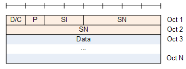
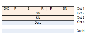
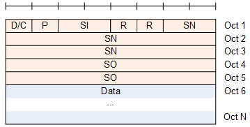
RLC AM PDU structure is illustrated below. D/C, P, SI are common to every types of AM PDU. The main difference is the length of SN field and the existence of SO field.
Following type carries SN field but does not carry SO(Segment Offset) field. It mean that this PDU non-segmented SDU(a complete SDU) or the first segment of a segmented SDU.
The length of SN field can be 12 or 18 bits. Which one to use is determined by RRC parameter : SN-FieldLengthAM.
< 38.322-Figure 6.2.1.4-1: AMD PDU with 12 bit SN (No SO) >
< 38.322-Figure 6.2.1.4-2: AMD PDU with 18 bit SN (No SO) >
The second type of AMD PDU carries SO as illustrated below. It mean that this PDU carries a Non-First segment of a segmented SDU. The length of SO field is always 16 bits.
< 38.322-Figure 6.2.1.4-3: AMD PDU with 12 bit SN with SO >
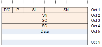
< 38.322-Figure 6.2.1.4-4: AMD PDU with 18 bit SN with SO >
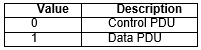
< 38.322-Table 6.2.2.6-1: D/C field interpretation >
< 38.322-Table 6.2.2.7-1: P field interpretation >

< 38.322-Table 6.2.2.4-1: SI field interpretation >
AMD Decoding Examples
The following examples show how to decode AMD PDUs from raw hex strings. These examples focus on the RLC AM header fields and use simple payload bytes for the data field. The SN length is determined by RRC configuration, so the receiver must know whether the bearer is configured with 12 bit SN or 18 bit SN before decoding the header.
Color code : D/C, P, SI, R, SN, SO, Data
Example 1 : AMD PDU With 12 Bit SN and Complete SDU
AM adds two header fields that UM does not have, and both sit in the first octet here. D/C separates a data PDU from a STATUS PDU. P asks the receiver for a status report. This PDU carries a complete SDU, so no SO field follows the SN.
Hex string : 81 23 DE AD BE EF
Binary String : 10000001 00100011 11011110 10101101 10111110 11101111
|
Field |
Bits / Bytes |
Value |
Decoding |
|---|---|---|---|
|
D/C |
bit 1 of octet 1 |
1 |
This is an RLC data PDU, not a control PDU. |
|
P |
bit 2 of octet 1 |
0 |
Polling is not requested by this AMD PDU. |
|
SI |
bits 3-4 of octet 1 |
00 |
The data field contains a complete RLC SDU. |
|
SN |
bits 5-8 of octet 1 and octet 2 |
0x123 = 291 |
The configured AM SN length is 12 bits, so the sequence number is 291. |
|
SO |
not present |
N/A |
A complete SDU does not carry the SO field. |
|
Data |
octets 3-6 |
DE AD BE EF |
Payload of the complete RLC SDU. |
The first two octets 81 23 are 10000001 00100011 in binary. D/C = 1 indicates data, P = 0 means no polling, SI = 00 means complete SDU, and the following 12 bits form SN = 0x123.
Example 2 : AMD PDU With 12 Bit SN, First Segment and Poll
The polling bit is what separates AM from UM, and this is the first example where it is set. P = 1 asks the receiver to report its reception state in a STATUS PDU. The PDU carries a first segment as well, so the SN is present and the SO field is not.
Hex string : D1 24 AA BB CC
Binary String : 11010001 00100100 10101010 10111011 11001100
|
Field |
Bits / Bytes |
Value |
Decoding |
|---|---|---|---|
|
D/C |
bit 1 of octet 1 |
1 |
This is an AMD data PDU. |
|
P |
bit 2 of octet 1 |
1 |
The transmitter requests a STATUS PDU from the peer AM entity. |
|
SI |
bits 3-4 of octet 1 |
01 |
This is the first segment of an RLC SDU. |
|
SN |
bits 5-8 of octet 1 and octet 2 |
0x124 = 292 |
This first segment belongs to SDU sequence number 292. |
|
SO |
not present |
N/A |
The first segment has an implicit offset of 0, so SO is not present. |
|
Data |
octets 3-5 |
AA BB CC |
Payload bytes of the first segment. |
The first two octets D1 24 are 11010001 00100100 in binary. D/C = 1 and P = 1 show that this is a polled data PDU, SI = 01 marks the first segment, and SN = 0x124 identifies the segmented SDU.
Example 3 : AMD PDU With 12 Bit SN and SO
An AM retransmission often replaces part of an SDU rather than all of it, and a PDU like this one carries that part. SI = 11 marks a middle segment, which is what makes the 16 bit SO field appear. The header therefore runs to four octets instead of two.
Hex string : B1 24 00 20 44 55
Binary String : 10110001 00100100 00000000 00100000 01000100 01010101
|
Field |
Bits / Bytes |
Value |
Decoding |
|---|---|---|---|
|
D/C |
bit 1 of octet 1 |
1 |
This is an AMD data PDU. |
|
P |
bit 2 of octet 1 |
0 |
Polling is not requested by this PDU. |
|
SI |
bits 3-4 of octet 1 |
11 |
This PDU is a middle segment, neither first nor last. |
|
SN |
bits 5-8 of octet 1 and octet 2 |
0x124 = 292 |
This segment belongs to the segmented SDU with SN 292. |
|
SO |
octets 3-4 |
00 20 = 32 |
The segment starts at byte offset 32 in the original SDU. |
|
Data |
octets 5-6 |
44 55 |
Payload bytes of this middle segment. |
The first two octets identify this as a 12 bit SN AMD PDU with SN = 0x124. Because SI = 11, the SO field is present and tells the receiver where this non-first segment belongs in the original SDU.
Example 4 : AMD PDU With 18 Bit SN and Complete SDU
An 18 bit SN is configured where the AM window has to cover more outstanding data than 12 bits allow. The wider SN changes the whole header layout, and this example shows the new positions. Two reserved bits appear after SI, and the SN then runs across three octets.
Hex string : C2 34 56 99 88
Binary String : 11000010 00110100 01010110 10011001 10001000
|
Field |
Bits / Bytes |
Value |
Decoding |
|---|---|---|---|
|
D/C |
bit 1 of octet 1 |
1 |
This is an RLC data PDU. |
|
P |
bit 2 of octet 1 |
1 |
The transmitter requests receiver status. |
|
SI |
bits 3-4 of octet 1 |
00 |
The data field contains a complete RLC SDU. |
|
R |
bits 5-6 of octet 1 |
00 |
Reserved bits for the 18 bit SN format. In this example they are set to 0. |
|
SN |
bits 7-8 of octet 1 and octets 2-3 |
0x23456 = 144470 |
The configured AM SN length is 18 bits, so the sequence number is 144470. |
|
SO |
not present |
N/A |
A complete SDU does not carry SO. |
|
Data |
octets 4-5 |
99 88 |
Payload of the complete RLC SDU. |
The first three octets C2 34 56 are 11000010 00110100 01010110 in binary. After D/C, P, SI and reserved bits, the next 18 bits form SN = 0x23456.
Example 5 : AMD PDU With 18 Bit SN and SO
This is the longest AMD header on the page, because it combines the 18 bit SN with the SO field. The SN takes three octets and the SO takes two more. Five header octets therefore have to be counted before the payload starts.
Hex string : A2 34 56 00 80 77 66
Binary String : 10100010 00110100 01010110 00000000 10000000 01110111 01100110
|
Field |
Bits / Bytes |
Value |
Decoding |
|---|---|---|---|
|
D/C |
bit 1 of octet 1 |
1 |
This is an AMD data PDU. |
|
P |
bit 2 of octet 1 |
0 |
Polling is not requested by this PDU. |
|
SI |
bits 3-4 of octet 1 |
10 |
This PDU contains the last segment of an RLC SDU. |
|
R |
bits 5-6 of octet 1 |
00 |
Reserved bits for 18 bit SN format. |
|
SN |
bits 7-8 of octet 1 and octets 2-3 |
0x23456 = 144470 |
This segment belongs to the SDU with sequence number 144470. |
|
SO |
octets 4-5 |
00 80 = 128 |
The last segment starts at byte offset 128 in the original SDU. |
|
Data |
octets 6-7 |
77 66 |
Payload bytes of the last segment. |
The first three octets decode the fixed AMD header for 18 bit SN. SI = 10 means last segment, so the 16 bit SO field is present after the SN field and indicates where this final segment begins inside the original SDU.
STATUS PDU
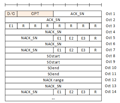
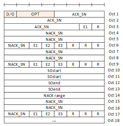
Status PDU is used to carry various RLC control information like ACK sequence Number, NACK sequence number or the exact location of the NACK in the unit of Bytes etc. The full stucture of Status PDU is as follows, but only D/C, CPT, ACK_SN field are always present and other fields may or may not present depending on situation. The receiving side of RLC can figure out whether thse additional fields (e.g, NACK SN, SO, NACK range etc) by checking the extention field (E1, E2, E3) which will be explained later.
< 38.322-Figure 6.2.2.5-1: STATUS PDU with 12 bit SN >
< 38.322-Figure 6.2.2.5-2: STATUS PDU with 18 bit SN >
< 38.322 - Table 6.2.3.11-1: E1 field interpretation >

< 38.322 - Table 6.2.3.13-1: E2 field interpretation >

< 38.322 - Table 6.2.3.16-1: E3 field interpretation >

STATUS PDU Decoding Examples
The following examples show how to decode STATUS PDUs from raw hex strings. In all examples, D/C = 0 indicates an RLC control PDU and CPT = 000 indicates STATUS PDU. The exact length of ACK_SN and NACK_SN depends on the AM SN length configured by RRC.
Color code : D/C, CPT, ACK_SN, E1/E2/E3, NACK_SN, SO, NACK range, R
Example 1 : STATUS PDU With 12 Bit SN, ACK Only
A STATUS PDU is how the AM receiver answers a poll, and the simplest answer is that nothing is missing. Only D/C, CPT and ACK_SN are always present. E1 = 0 then closes the PDU, because no NACK_SN field follows it.
Hex string : 00 11 00
Binary String : 00000000 00010001 00000000
|
Field |
Bits / Bytes |
Value |
Decoding |
|---|---|---|---|
|
D/C |
bit 1 of octet 1 |
0 |
This is an RLC control PDU. |
|
CPT |
bits 2-4 of octet 1 |
000 |
The control PDU type is STATUS PDU. |
|
ACK_SN |
bits 5-8 of octet 1 and octet 2 |
0x011 = 17 |
All AMD PDUs up to but not including SN 17 are acknowledged, since no NACK is present. |
|
E1 |
bit 1 of octet 3 |
0 |
No NACK_SN field follows. |
|
R |
bits 2-8 of octet 3 |
0000000 |
Reserved bits. In this example they are set to 0. |
This is the simplest STATUS PDU example. The receiver is telling the transmitter that everything before ACK_SN 17 has been received and there is no missing SN to retransmit.
Example 2 : STATUS PDU With 12 Bit SN and One NACK
One lost AMD PDU is the ordinary case, and this example is the shortest way to report it. E1 = 1 adds a single NACK_SN after the ACK_SN. The three extension bits that follow the NACK_SN then say that nothing further is appended.
Hex string : 01 23 80 12 00
Binary String : 00000001 00100011 10000000 00010010 00000000
|
Field |
Bits / Bytes |
Value |
Decoding |
|---|---|---|---|
|
D/C |
bit 1 of octet 1 |
0 |
This is an RLC control PDU. |
|
CPT |
bits 2-4 of octet 1 |
000 |
The control PDU type is STATUS PDU. |
|
ACK_SN |
bits 5-8 of octet 1 and octet 2 |
0x123 = 291 |
Reception state is reported up to SN 291, with exceptions listed by NACK fields. |
|
E1 |
bit 1 of octet 3 |
1 |
At least one NACK_SN field follows. |
|
NACK_SN |
octet 4 and bits 1-4 of octet 5 |
0x120 = 288 |
SN 288 is missing and should be retransmitted. |
|
E1/E2/E3 |
bits 5-7 of octet 5 |
000 |
No additional NACK, no SO range and no NACK range follows this NACK_SN. |
This STATUS PDU says that SN 288 is missing while the receiver state has progressed up to ACK_SN 291. The transmitter should retransmit SN 288 if it is still available in the retransmission buffer.
Example 3 : STATUS PDU With Segment-Level NACK
A whole SDU is not always lost. When only part of it fails, asking for the whole SN again wastes air time, and E2 exists for that reason. E2 adds SOstart and SOend after the NACK_SN, so the report names a byte range inside one SDU.
Hex string : 00 34 80 03 24 00 10 00 1F
Binary String : 00000000 00110100 10000000 00000011 00100100 00000000 00010000 00000000 00011111
|
Field |
Bits / Bytes |
Value |
Decoding |
|---|---|---|---|
|
D/C |
bit 1 of octet 1 |
0 |
This is an RLC control PDU. |
|
CPT |
bits 2-4 of octet 1 |
000 |
The control PDU type is STATUS PDU. |
|
ACK_SN |
bits 5-8 of octet 1 and octet 2 |
0x034 = 52 |
The receiver reports status up to SN 52, with one segment-level exception. |
|
E1 |
bit 1 of octet 3 |
1 |
A NACK_SN field follows. |
|
NACK_SN |
octet 4 and bits 1-4 of octet 5 |
0x032 = 50 |
The missing part belongs to SN 50. |
|
E1/E2/E3 |
bits 5-7 of octet 5 |
010 |
E2 = 1 means SOstart and SOend are present for this NACK_SN. |
|
SOstart |
octets 6-7 |
0x0010 = 16 |
The missing segment starts at byte offset 16. |
|
SOend |
octets 8-9 |
0x001F = 31 |
The missing segment ends at byte offset 31. |
This STATUS PDU does not ask for the whole SN 50 again. It requests retransmission of only the missing byte range from SOstart 16 to SOend 31.
Example 4 : STATUS PDU With NACK Range
Losses often arrive in bursts, and listing every missing SN separately makes the STATUS PDU long. E3 answers that with a NACK range field. One NACK_SN plus a count then covers a run of consecutive SDUs.
Hex string : 02 05 80 20 02 03
Binary String : 00000010 00000101 10000000 00100000 00000010 00000011
|
Field |
Bits / Bytes |
Value |
Decoding |
|---|---|---|---|
|
D/C |
bit 1 of octet 1 |
0 |
This is an RLC control PDU. |
|
CPT |
bits 2-4 of octet 1 |
000 |
The control PDU type is STATUS PDU. |
|
ACK_SN |
bits 5-8 of octet 1 and octet 2 |
0x205 = 517 |
The receiver reports status up to SN 517. |
|
NACK_SN |
octet 4 and bits 1-4 of octet 5 |
0x200 = 512 |
The first missing SN in the range is SN 512. |
|
E1/E2/E3 |
bits 5-7 of octet 5 |
001 |
E3 = 1 means a NACK range field follows. |
|
NACK range |
octet 6 |
3 |
Three consecutive SDUs starting from SN 512 are missing. |
This example compactly reports a burst loss. Instead of listing SN 512, SN 513 and SN 514 separately, the STATUS PDU uses one NACK_SN and a NACK range value of 3.
Example 5 : STATUS PDU With 18 Bit SN and One NACK
The 18 bit SN configuration changes where every later field sits, and a decoder that assumes 12 bits reads this PDU wrongly. The content is the same single NACK as in the 12 bit case. Only the bit positions move, and they move because of RRC configuration rather than because of anything inside the PDU.
Hex string : 00 00 4A 00 04 00
Binary String : 00000000 00000000 01001010 00000000 00000100 00000000
|
Field |
Bits / Bytes |
Value |
Decoding |
|---|---|---|---|
|
D/C |
bit 1 of octet 1 |
0 |
This is an RLC control PDU. |
|
CPT |
bits 2-4 of octet 1 |
000 |
The control PDU type is STATUS PDU. |
|
ACK_SN |
bits 5-8 of octet 1, octet 2 and bits 1-6 of octet 3 |
0x00012 = 18 |
The STATUS PDU uses the 18 bit AM SN format and reports state up to SN 18. |
|
E1 |
bit 7 of octet 3 |
1 |
A NACK_SN field follows. |
|
NACK_SN |
octets 4-5 and bits 1-2 of octet 6 |
0x00010 = 16 |
SN 16 is missing and should be retransmitted. |
|
E1/E2/E3 |
bits 3-5 of octet 6 |
000 |
No additional NACK, SO fields or NACK range follows. |
This example is similar to the 12 bit single-NACK case, but the ACK_SN and NACK_SN fields are longer. The receiver must use the configured 18 bit AM SN length to parse the bit positions correctly.
RRC Parameters defining RLC
RLC behavior is not determined only by the RLC mode itself. The actual operation is configured by RRC through RLC-BearerConfig and the related RLC-Config parameters. These parameters decide which logical channel is served, whether the bearer uses TM, UM or AM, the uplink and downlink RLC entity configuration, sequence number length, timers, polling thresholds and retransmission related behavior. Because of this, when debugging RLC operation, it is important to read the RRC configuration first and then interpret the observed RLC PDUs based on that configuration.
Two things are worth knowing before reading the listing. The first is that RLC-BearerConfig binds the logical channel, the RLC mode and the MAC logical channel parameters together, so it is the IE a log analysis starts from. The second is that these parameters have grown release by release since Release 15. Release 16, Release 17 and Release 19 each added fields, and the added fields sit in the extension groups at the end of the IE rather than in its original body.
Following is based on
RLC-BearerConfig ::=                        SEQUENCE {
    logicalChannelIdentity                      LogicalChannelIdentity,
    servedRadioBearer                           CHOICE {
        srb-Identity                                SRB-Identity,
        drb-Identity                                DRB-Identity
    }                                                                                               OPTIONAL,   -- Cond LCH-SetupOnly
    reestablishRLC                              ENUMERATED {true}                                   OPTIONAL,   -- Need N
    rlc-Config                                  RLC-Config                                          OPTIONAL,   -- Cond LCH-Setup
    mac-LogicalChannelConfig                    LogicalChannelConfig                                OPTIONAL,   -- Cond LCH-Setup
    ...,
    [[
    rlc-Config-v1610                            RLC-Config-v1610                                    OPTIONAL    -- Need R
    ]],
    [[
    rlc-Config-v1700                            RLC-Config-v1700                                    OPTIONAL,   -- Need R
    logicalChannelIdentityExt-r17               LogicalChannelIdentityExt-r17                       OPTIONAL,   -- Cond LCH-SetupModMRB
    multicastRLC-BearerConfig-r17               MulticastRLC-BearerConfig-r17                       OPTIONAL,   -- Cond LCH-SetupOnlyMRB
    servedRadioBearerSRB4-r17                   SRB-Identity-v1700                                  OPTIONAL    -- Cond LCH-SetupOnlySRB4
    ]],
    [[
    servedRadioBearerSRB5-r18                   SRB-Identity-v1800                                  OPTIONAL    -- Cond LCH-SetupOnlySRB5
    ]],
    [[
    rlc-Config-v1900                            RLC-Config-v1900                                    OPTIONAL,   -- Need R
    servedRadioBearerSRB6-r19                   SRB-Identity-v1900                                  OPTIONAL  -- Cond LCH-SetupOnlySRB6
    ]]
}

MulticastRLC-BearerConfig-r17 ::=           SEQUENCE {
    servedMBS-RadioBearer-r17                   MRB-Identity-r17,
    isPTM-Entity-r17                            ENUMERATED {true}                                   OPTIONAL    -- Need S
}

LogicalChannelIdentityExt-r17 ::=           INTEGER (320..65855)
The four bracket groups after the extension marker are what a Release 15 listing does not have. Each group carries one release. The Release 17 group is the largest, and it is largest because of MBS. The field multicastRLC-BearerConfig-r17 lets an RLC bearer serve a multicast radio bearer. Beside it, logicalChannelIdentityExt-r17 widens the logical channel identity range to 320..65855, so that multicast channels do not collide with unicast ones. The remaining fields extend the SRB range. Release 17 reaches SRB4, Release 18 reaches SRB5, and Release 19 reaches SRB6.
RLC-Config is the IE that actually selects the mode. It is a CHOICE, so exactly one of am, um-Bi-Directional, um-Uni-Directional-UL and um-Uni-Directional-DL is present. That is where the TM, UM and AM distinction of this page becomes a concrete configuration. TM has no branch here, because TM needs no parameters at all.
Following is based on
RLC-Config ::=                      CHOICE {
    am                                  SEQUENCE {
        ul-AM-RLC                           UL-AM-RLC,
        dl-AM-RLC                           DL-AM-RLC
    },
    um-Bi-Directional                   SEQUENCE {
        ul-UM-RLC                           UL-UM-RLC,
        dl-UM-RLC                           DL-UM-RLC
    },
    um-Uni-Directional-UL               SEQUENCE {
        ul-UM-RLC                           UL-UM-RLC
    },
    um-Uni-Directional-DL               SEQUENCE {
        dl-UM-RLC                           DL-UM-RLC
    },
    ...
}

UL-AM-RLC ::=                       SEQUENCE {
    sn-FieldLength                      SN-FieldLengthAM                                    OPTIONAL,   -- Cond Reestab
    t-PollRetransmit                    T-PollRetransmit,
    pollPDU                             PollPDU,
    pollByte                            PollByte,
    maxRetxThreshold                    ENUMERATED { t1, t2, t3, t4, t6, t8, t16, t32 }
}

DL-AM-RLC ::=                       SEQUENCE {
    sn-FieldLength                      SN-FieldLengthAM                                    OPTIONAL,   -- Cond Reestab
    t-Reassembly                        T-Reassembly,
    t-StatusProhibit                    T-StatusProhibit
}

UL-UM-RLC ::=                       SEQUENCE {
    sn-FieldLength                      SN-FieldLengthUM                                    OPTIONAL    -- Cond Reestab
}

DL-UM-RLC ::=                       SEQUENCE {
    sn-FieldLength                      SN-FieldLengthUM                                    OPTIONAL,   -- Cond Reestab
    t-Reassembly                        T-Reassembly
}

SN-FieldLengthUM ::=                ENUMERATED {size6, size12}
SN-FieldLengthAM ::=                ENUMERATED {size12, size18}
Two fields in this group decide how the PDUs earlier on this page are parsed, and both are called sn-FieldLength. On the UM side the choice is size6 or size12, which are the 6 bit and the 12 bit UM SN. On the AM side the choice is size12 or size18, which are the 12 bit and the 18 bit AM SN. Both fields are marked OPTIONAL with -- Cond Reestab, so either may be absent in a reconfiguration that only re-establishes the entity. In that case the previously configured length continues to apply.
The timer and counter types are separate IEs because several of them are reused. T-Reassembly appears in both DL-AM-RLC and DL-UM-RLC, and it is the timer that decides how long the receiver waits for a missing segment before it gives up. The three polling controls belong to the uplink AM entity only. Two of them, pollPDU and pollByte, set a poll after a number of PDUs or after a number of bytes. The third, t-PollRetransmit, sets a poll after silence.
Following is based on
T-PollRetransmit ::=                ENUMERATED {
                                        ms5, ms10, ms15, ms20, ms25, ms30, ms35,
                                        ms40, ms45, ms50, ms55, ms60, ms65, ms70,
                                        ms75, ms80, ms85, ms90, ms95, ms100, ms105,
                                        ms110, ms115, ms120, ms125, ms130, ms135,
                                        ms140, ms145, ms150, ms155, ms160, ms165,
                                        ms170, ms175, ms180, ms185, ms190, ms195,
                                        ms200, ms205, ms210, ms215, ms220, ms225,
                                        ms230, ms235, ms240, ms245, ms250, ms300,
                                        ms350, ms400, ms450, ms500, ms800, ms1000,
                                        ms2000, ms4000, ms1-v1610, ms2-v1610, ms3-v1610,
                                        ms4-v1610, spare1}

PollPDU ::=                         ENUMERATED {
                                        p4, p8, p16, p32, p64, p128, p256, p512, p1024, p2048, p4096, p6144, p8192, p12288, p16384,p20480,
                                        p24576, p28672, p32768, p40960, p49152, p57344, p65536, infinity, spare8, spare7, spare6, spare5, spare4,
                                        spare3, spare2, spare1}

PollByte ::=                        ENUMERATED {
                                        kB1, kB2, kB5, kB8, kB10, kB15, kB25, kB50, kB75,
                                        kB100, kB125, kB250, kB375, kB500, kB750, kB1000,
                                        kB1250, kB1500, kB2000, kB3000, kB4000, kB4500,
                                        kB5000, kB5500, kB6000, kB6500, kB7000, kB7500,
                                        mB8, mB9, mB10, mB11, mB12, mB13, mB14, mB15,
                                        mB16, mB17, mB18, mB20, mB25, mB30, mB40, infinity,
                                        spare20, spare19, spare18, spare17, spare16,
                                        spare15, spare14, spare13, spare12, spare11,
                                        spare10, spare9, spare8, spare7, spare6, spare5,
                                        spare4, spare3, spare2, spare1}

T-Reassembly ::=                    ENUMERATED {
                                        ms0, ms5, ms10, ms15, ms20, ms25, ms30, ms35,
                                        ms40, ms45, ms50, ms55, ms60, ms65, ms70,
                                        ms75, ms80, ms85, ms90, ms95, ms100, ms110,
                                        ms120, ms130, ms140, ms150, ms160, ms170,
                                        ms180, ms190, ms200, spare1}

T-StatusProhibit ::=                ENUMERATED {
                                        ms0, ms5, ms10, ms15, ms20, ms25, ms30, ms35,
                                        ms40, ms45, ms50, ms55, ms60, ms65, ms70,
                                        ms75, ms80, ms85, ms90, ms95, ms100, ms105,
                                        ms110, ms115, ms120, ms125, ms130, ms135,
                                        ms140, ms145, ms150, ms155, ms160, ms165,
                                        ms170, ms175, ms180, ms185, ms190, ms195,
                                        ms200, ms205, ms210, ms215, ms220, ms225,
                                        ms230, ms235, ms240, ms245, ms250, ms300,
                                        ms350, ms400, ms450, ms500, ms800, ms1000,
                                        ms1200, ms1600, ms2000, ms2400, spare2, spare1}
T-PollRetransmit is the one enumeration on this page that changed after Release 15. The four spare values at the end were replaced in Release 16 by ms1-v1610, ms2-v1610, ms3-v1610 and ms4-v1610. The reason is latency. The shortest value in the Release 15 list was 5 ms, and 5 ms is too coarse for URLLC. So four sub-5 ms values were added, and only one spare was left.
The release extensions referenced from RLC-BearerConfig are defined separately, and they are short. Each one adds a single behaviour rather than a new mode.
Following is based on
RLC-Config-v1610 ::=                SEQUENCE {
    dl-AM-RLC-v1610                     DL-AM-RLC-v1610
}

RLC-Config-v1700 ::=                SEQUENCE {
    dl-AM-RLC-v1700                     DL-AM-RLC-v1700,
    dl-UM-RLC-v1700                     DL-UM-RLC-v1700
}

RLC-Config-v1900 ::=                SEQUENCE {
    dl-AM-RLC-v1900                     DL-AM-RLC-v1900,
    ul-AM-RLC-v1900                     UL-AM-RLC-v1900
}

DL-AM-RLC-v1610 ::=                 SEQUENCE {
    t-StatusProhibit-v1610              T-StatusProhibit-v1610                               OPTIONAL,   -- Need R
    ...
}

DL-AM-RLC-v1700 ::=                 SEQUENCE {
    t-ReassemblyExt-r17                 T-ReassemblyExt-r17                                  OPTIONAL    -- Need R
}

DL-AM-RLC-v1900 ::=                 SEQUENCE {
    t-RxDiscard-r19                     T-RxDiscard-r19                                      OPTIONAL    -- Need R
}

UL-AM-RLC-v1900 ::=                 SEQUENCE {
    stopReTxDiscardedSDU-r19            ENUMERATED {enabled}                                 OPTIONAL    -- Need R
}

DL-UM-RLC-v1700 ::=                 SEQUENCE {
    t-ReassemblyExt-r17                 T-ReassemblyExt-r17                                  OPTIONAL    -- Need R
}

T-StatusProhibit-v1610 ::=          ENUMERATED { ms1, ms2, ms3, ms4, spare4, spare3, spare2, spare1}

T-ReassemblyExt-r17 ::=             ENUMERATED {ms210, ms220, ms340, ms350, ms550, ms1100, ms1650, ms2200}

T-RxDiscard-r19 ::=                 ENUMERATED {ms10, ms20, ms30, ms40, ms50, ms60, ms75, ms100, ms150, ms200, ms250, ms300,
                                                ms400, ms500, ms750, ms1000, ms1500, ms2000, ms3000, spare13, spare12, spare11, spare10,
                                                spare9, spare8, spare7, spare6, spare5, spare4, spare3, spare2, spare1}
Four added fields matter to how AM behaves. The first, t-StatusProhibit-v1610, extends the STATUS prohibit timer downward to 1, 2, 3 and 4 ms. The reason is the same URLLC reason as for the poll timer. The second, t-ReassemblyExt-r17, extends the reassembly timer upward instead, as far as 2200 ms. That range is what NTN round trip times need. The third, t-RxDiscard-r19, lets the receiving AM entity discard an SDU it has waited too long for. The fourth, stopReTxDiscardedSDU-r19, lets the transmitting AM entity stop retransmitting an SDU that the discard timer has already removed. The last two are a pair. Together they stop a bearer transmitting data that is no longer useful.
RLC-BearerConfig is the starting point for any RLC log analysis : it names the logical channel, selects the mode through rlc-Config, and carries the MAC logical channel parameters for the same bearer.sn-FieldLength has to be read before any PDU is decoded : the header layouts on this page differ only by SN width. Nothing in the PDU itself says which width is in use.An absent sn-FieldLength is not a default : the field is marked -- Cond Reestab, so its absence means the previously configured length still applies.The release extensions move timers in both directions : Release 16 and Release 17 shortened the poll and status timers for URLLC, while Release 17 lengthened the reassembly timer for NTN.Release 19 added a discard path to AM : t-RxDiscard-r19 lets the receiver give up on a stale SDU, and stopReTxDiscardedSDU-r19 stops the transmitter retransmitting it.
Reference
[1]