As it says, SRB stands for Signaling Radio Bearer. In other words, SRB is a type of Radio Bearer that carries signaling message (i.e, RRC or/and NAS message). The word that matters there is only. An SRB carries RRC and NAS messages and nothing else, and that restriction is the whole difference between an SRB and a DRB. A DRB carries user data. Both are built the same way, over PDCP, RLC, MAC and PHY, so the difference is not in the stack. It is in what the bearer is allowed to carry, and in how carefully it is treated.
There is a second reason to keep the two apart, and it shapes the rest of this page. A data bearer has to be set up by signalling. So the signalling path cannot itself depend on a data bearer existing, or nothing could ever be established in the first place. The network needs a way to reach a UE that holds no configuration at all. That is what SRB0 is for, and it is why SRB0 needs no configuration of its own. Every other bearer is built on top of that first exchange, signalling and data alike.
An SRB carries two kinds of message, and they are not the same traffic either. An RRC message is generated and consumed by the RAN, so the gNB reads it and acts on it. A NAS message is generated by the UE and the core network, and the gNB only carries it. It travels inside an RRC message that adds no RRC control information of its own. So a NAS message needs two things: a radio bearer to the gNB, and a connection onward to the AMF. The illustration further down draws both legs. Protection is doubled for the same reason. Once AS security is activated, PDCP integrity protects and ciphers every RRC message on SRB1 and above, including the ones that carry NAS. NAS then applies its own integrity protection and ciphering independently on top.
- Why we should have so many different type of SRB ?
- Default SRB Configuration
- How is that priority implemented in the protocol stack ?
- SRB Mapping to Signalling Message
- SRB4, SRB5 and SRB6
- RRC Parameters
- Reference
According to 38.331 4.2.2 Signalling radio bearers, there are seven different types of SRB in NR defined as follows.
SRB0 is for RRC messages using the CCCH logical channel;SRB1 is for RRC messages (which may include a piggybacked NAS message) as well as for NAS messages prior to the establishment of SRB2, all using DCCH logical channel;SRB2 is for NAS messages and for RRC messages which include logged measurement information, all using DCCH logical channel. SRB2 has a lower-priority than SRB1 and may be configured by the network after AS security activation;SRB3 is for specific RRC messages when UE is in (NG)EN-DC or NR-DC, all using DCCH logical channel;SRB4 is for RRC messages which include application layer measurement report information, all using DCCH logical channel. SRB4 has a lower priority than SRB1 and can only be configured by the network after AS security activation;SRB5 is for RRC messages which include application layer measurement report information, all using DCCH logical channel. SRB5 has a lower priority than SRB1 and SRB3 and can only be configured by the SN serving the SCG when the UE is in NR-DC, after AS security activation;SRB6 is for RRC messages which include logged measurement information for network-side data collection, all using DCCH logical channel. SRB6 has a lower priority than SRB1 and can only be configured by the network after AS security activation.
As you may notice, the type and functions of each SRB in NR is same as the SRBs in LTE except that NR has one more SRB called SRB3. That was true when this note was first written. Releases 17, 18 and 19 have since added SRB4, SRB5 and SRB6, and the last section of this page covers what they are for. Regarding SRB3, 36.331 4.2.2 has a short additional comments as below.
In case of EN-DC, SRB3 may be configured for the transfer of some NR RRC messages between UE and SgNB via the NR radio interface.
The SRB structure is well illustrated by Rahim Navael as shown below. Rahim kindly approved me to share the illustration in my note.
Before reading the drawing, here is what it sets out. On the left the UE and the gNB face each other across the NR Uu interface, and the downlink and uplink physical channels are named along the beams. On the right the gNB reaches the AMF over NGAP on N2, and the AMF reaches the UE over N1 for NAS. The three horizontal bars between UE and gNB are SRB0, SRB1 and SRB2. The NG-C bearer is the bar that continues on to the AMF, and the two together are labelled the Signaling Connection. The column down the right hand side is the mapping chain from RRC message to logical channel to transport channel to physical channel.
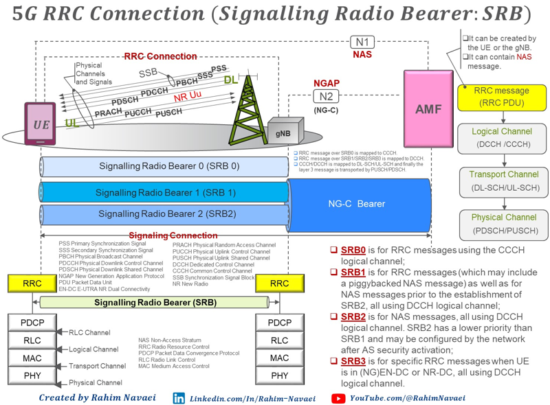
Image Source : Rahim Navaei's linked in post
- The three SRB bars stop at the gNB. Only the NG-C bearer carries on to the AMF, which is why a NAS message needs both legs to arrive.
- The note in the middle states the mapping in one line. SRB0 maps to CCCH, SRB1, SRB2 and SRB3 map to DCCH, CCCH and DCCH map to DL-SCH and UL-SCH, and the layer 3 message is finally carried on PDSCH or PUSCH.
- The two protocol stacks at the bottom show where an SRB actually lives. It runs between the two RRC entities, over PDCP, RLC, MAC and PHY at each end.
- The SRB definitions at the lower right already read "(NG)EN-DC or NR-DC" for SRB3, which is the wording the current 38.331 uses.
Why we should have so many different type of SRB ?
Seven signalling radio bearers looks like a lot for one job, and the obvious question is why one would not do. The question is worth answering properly, because the answer explains almost every design choice further down this page. The short version is that the seven are not seven versions of the same thing. Each one was added to separate signalling along a different axis, and there are only four axes. Once you can name them, the default values and the message mapping stop looking arbitrary.
Start with the alternative. Suppose the network had one signalling bearer and used it for everything. That bearer would have to be usable before the UE holds any configuration, and also protected by PDCP once security is activated. It would have to be high priority, so a handover command is never delayed, and low priority, so a large measurement report never delays one. It would have to terminate in the master node and in the secondary node at the same time. Those are not difficult requirements. They are contradictory ones, and no amount of configuration resolves a contradiction.
The first axis is time, and it produces SRB0. Before the UE holds a dedicated configuration there is nothing to configure a bearer with, so the first bearer has to be one both sides already agree on. SRB0 is that agreement. It runs on CCCH in RLC transparent mode, with no PDCP entity and no security, and it is the only SRB that never appears in RadioBearerConfig at all.
The second axis is urgency, and it separates SRB1 from SRB2. This pair is the one most often misread, because SRB2 does not add a capability. NAS travels perfectly well on SRB1, and clause 4.2.2 says so directly: SRB1 carries NAS messages prior to the establishment of SRB2. So the network is not waiting for SRB2 before it can send NAS. What SRB2 adds is a second queue at a lower priority. The default values make the intent plain, at priority 1 for SRB1 and 3 for SRB2. A long NAS exchange therefore cannot sit in front of an RRC reconfiguration.
Shared spectrum makes the same point from another direction. For operation with shared spectrum channel access in FR1, SRB0, SRB1 and SRB3 are assigned the highest priority Channel Access Priority Class, CAPC 1. The class for SRB2 is left configurable. Three bearers are treated as always urgent. The one carrying NAS is not.
The third axis is the termination point, and only SRB3 sits on it. This is the one SRB that adds a capability rather than a separation. In (NG)EN-DC or NR-DC the secondary node has its own RRC decisions to make, and without SRB3 every one of them would travel through the master node and back. SRB3 gives the SN a direct path to the UE. That is also why SRB3 uses the secondary key while SRB1 and SRB2 use the master key, and why its default priority is 1 rather than 3. It does the same urgent work as SRB1, from the other node.
The fourth axis is volume, and it produced SRB4, SRB5 and SRB6. An RRC procedure message is small. An application layer measurement report is not, and neither is a logged measurement record. Putting one on SRB1 would let it delay mobility signalling, and putting it on SRB2 would mix it with NAS. So Releases 17, 18 and 19 each added a bearer below SRB1 in priority instead. The section on those three works through the detail.
There is a cost side as well, and it explains why the count grew slowly rather than being reserved in advance. Every SRB costs a logical channel identity, a PDCP entity, an RLC entity and the RRC signalling to configure it. So 3GPP added them one at a time, as a specific need appeared. The identifier is the clearest evidence of that. SRB-Identity was defined as INTEGER (1..3), and it had to be extended three separate times, once per release, rather than being widened once.
Set side by side, the four axes and the bearers on each look like this.
|
Axis of separation |
SRBs |
What it prevents |
|
Time : before any configuration exists |
SRB0 |
a bearer that cannot be set up, because setting one up needs a bearer |
|
Urgency : bulk signalling behind urgent signalling |
SRB1, SRB2 |
a long NAS exchange sitting in front of an RRC procedure |
|
Termination point : which node is speaking |
SRB3 |
every secondary node decision detouring through the master node |
|
Volume : large reports behind everything else |
SRB4, SRB5, SRB6 |
a measurement report delaying mobility signalling |
Seven bearers, but only four reasons : time, urgency, termination point and volume. Every SRB past SRB0 exists because one of those four could not be met by an existing bearer.SRB2 adds separation, not capability : NAS already travels on SRB1 before SRB2 exists. What SRB2 provides is a lower priority queue, so bulk NAS cannot delay an RRC procedure.SRB3 is the exception, because it adds a path : it is the only one that lets a different node reach the UE directly. That is why it carries the secondary key.Priority is what makes the separation real : without different priority values, separate bearers would simply compete equally for the same grant and buy nothing.The count grew one release at a time : SRB-Identity was INTEGER (1..3) and needed three separate extensions. Nobody reserved room for seven bearers in advance.
Default SRB Configuration
These values are not something an operator tunes. They are the defaults that 38.331 clause 9.2.1 fixes for SRB1, SRB2 and SRB3, and the UE applies them whenever the network sends no explicit configuration. So do not read an RRCSetup as truncated when none of these fields appears in it. It means the UE applied exactly this table instead. Notice which columns exist as well, because both of the missing ones have a reason.
|
RRC information elements |
SRB1/1S |
SRB2/2S |
SRB3 |
|
PDCP-Config |
|
|
|
|
t-Reordering |
Infinity |
Infinity |
Infinity |
|
RLC-Config CHOICE |
AM |
AM |
AM |
|
ul-RLC-Config |
|
|
|
|
sn-FieldLength |
size12 |
size12 |
size12 |
|
t-PollRetransmit |
ms45 |
ms45 |
ms45 |
|
pollPDU |
Infinity |
Infinity |
Infinity |
|
pollByte |
Infinity |
Infinity |
Infinity |
|
maxRetxThreshold |
t8 |
t8 |
t8 |
|
dl-RLC-Config |
|
|
|
|
sn-FieldLength |
size12 |
size12 |
size12 |
|
t-Reassembly |
ms35 |
ms35 |
ms35 |
|
t-StatusProhibit |
ms0 |
ms0 |
ms0 |
|
logicalChannelIdentity |
1 |
2 |
3 |
|
LogicalChannelConfig |
|
|
|
|
priority |
1 |
3 |
1 |
|
prioritisedBitRate |
Infinity |
Infinity |
Infinity |
|
logicalChannelGroup |
0 |
0 |
0 |
There is no SRB0 column because there is nothing to configure. SRB0 runs on CCCH with RLC in transparent mode and no PDCP entity, and it has to work before the UE holds any dedicated configuration at all. There is no SRB4, SRB5 or SRB6 column either, and that absence has a consequence covered in the last section of this page.
Read the RLC rows together and one design choice explains all of them. All three bearers use AM with a 12 bit sequence number, so every signalling message is acknowledged and retransmitted. The fields pollPDU and pollByte are both infinity, so neither a count of PDUs nor a count of bytes ever triggers a status poll. Signalling traffic is small and bursty, so a volume trigger would almost never fire. t-PollRetransmit at ms45 and maxRetxThreshold at t8 carry the reliability instead.
The PDCP row says the same thing in a different way. t-Reordering is infinity, so the UE waits indefinitely rather than delivering a gap upward. For user data that would be a poor choice, because a stalled flow is worse than a lost packet. For signalling it is the right one, because an RRC procedure fails outright if it loses a message.
The last three rows set how the bearers compete for a grant. The priority field is 1 for SRB1, 3 for SRB2 and 1 for SRB3, and a lower number wins. So SRB2 yields to SRB1, which is what clause 4.2.2 states in words. SRB3 sits level with SRB1 rather than below it. Then prioritisedBitRate is infinity for all three, so none of them is rate limited. Finally logicalChannelGroup is 0 for all three, so a BSR reports the signalling volume of all of them in one group.
One convenience is worth pointing out because it makes a log readable. With these defaults in force, logicalChannelIdentity is 1, 2 and 3 for SRB1, SRB2 and SRB3, and srb-Identity carries the same three values. So an LCID of 2 on DCCH is SRB2, with no lookup needed.
An absent configuration is not an unconfigured bearer : when the network sends no PDCP-Config or RLC-Config for SRB1, SRB2 or SRB3, the UE applies this table. The fields are missing from the log, not from the bearer.Signalling is configured for reliability, not for throughput : RLC AM everywhere, no volume based polling, and a PDCP reordering timer of infinity. Every setting trades delay for delivery.SRB3 is configured like SRB1, not like SRB2 : same priority 1 and the same RLC timers. Only its logical channel identity and its termination point differ.The table stops at SRB3 for a reason : SRB0 has nothing to configure, and SRB4, SRB5 and SRB6 postdate the table, so the network has to configure them explicitly.
How is that priority implemented in the protocol stack ?
The table above gives SRB1 a priority of 1 and SRB2 a priority of 3, and the previous section claimed those numbers are what makes the separation real. That claim is worth checking, because a priority value on its own does nothing. Something has to read it. That something is the Logical Channel Prioritization procedure in MAC, and it runs in the UE every time a new uplink transmission is built from a grant.
One convention first, because it is easy to misread. 38.321 states that an increasing priority value indicates a lower priority level. So 1 is the strongest value, not the weakest, and SRB2 at 3 genuinely sits behind SRB1 at 1.
The procedure runs in three steps. First, each logical channel keeps a token bucket called Bj, which grows at the prioritisedBitRate and is capped at prioritisedBitRate multiplied by bucketSizeDuration. Second, the UE selects the channels this particular grant is allowed to serve, filtering on the mapping restrictions in LogicalChannelConfig such as allowedSCS-List, maxPUSCH-Duration and allowedCG-List. An SRB normally has none of those configured, so it is eligible for any grant. Third, the UE allocates the grant.
That third step happens in two rounds, and the SRB defaults are designed for the first one. Channels with Bj above zero are served in decreasing priority order, up to their prioritised bit rate. Then comes the sentence that matters most for signalling. If the prioritisedBitRate of a channel is set to infinity, the UE allocates resources for all data available on it before meeting the prioritised bit rate of any lower priority channel. Every SRB is required to use infinity, and the sub-section below shows that this is a constraint rather than a default. So every pending byte of signalling is placed in the grant before a single DRB reaches even its guaranteed rate.
If the grant still has room, the second round serves every selected channel again in strict decreasing priority order, and Bj is ignored this time. It continues until either the data or the grant runs out. Channels of equal priority should be served equally.
The drawing below shows the same grant filled twice, from two different buffer states, with the fixed order of service beneath it.
Nothing in the grant is reserved. When SRB1 has nothing pending, everything below it moves up and the DRB receives far more of the same grant. The order is fixed, the sizes are not.
Two things about that drawing are worth stating plainly, because a row of blocks invites the wrong reading. Nothing in the grant is set aside in advance. The blocks are the outcome of one allocation pass, and they move whenever the buffers move. That is why the same grant size carries a much larger DRB block in the second row. SRB1 simply had nothing pending.
The second point is where those blocks come from. Each SRB and each DRB has its own PDCP entity and its own RLC entity, so each one really does have a separate transmission buffer. What they share begins at MAC. One MAC entity per cell group multiplexes all of them into a single MAC PDU, which is the reason LCP has to exist. The MAC control elements are not a buffer in that sense at all. A MAC procedure generates them on demand, so a BSR appears because data arrived rather than because something was queued. One consequence is worth noting, since SRB1 and SRB3 share a priority of 1. They never meet in the same allocation, because they sit in different cell groups and a different MAC entity builds each grant.
The first two boxes of the order strip above are the part the priority fields never reach, and it answers a question the default table raises. SRB0 has no priority value at all, because it has no LogicalChannelConfig and never appears in RadioBearerConfig. So how does it get served first ? Clause 5.4.3.1.3 closes with a fixed list that orders MAC control elements and CCCH data against each other. Data from UL-CCCH sits at the very top of it, level with the C-RNTI MAC CE. No configuration takes part.
The same list carries a consequence that surprises people. Ordinary logical channel data appears in it as a single line, well down the order, below almost every MAC control element. A Buffer Status Report therefore outranks SRB1 data, and no priority value can change that. Only a BSR included purely as padding falls below the data line.
Release 19 adds one twist through enhancedLCP. A logical channel configured with priorityAdjustmentThreshold applies additionalPriority instead of priority when the remaining discardTimer of a buffered PDCP SDU drops below that threshold. It reverts once no such SDU is left. So the priority of a channel is no longer strictly static.
Finally, it is worth separating this mechanism from three others that share the word priority and are easy to confuse with it.
|
Mechanism |
Where it lives |
What it actually decides |
|
priority, prioritisedBitRate, bucketSizeDuration |
MAC, 38.321 5.4.3.1 |
the order in which logical channel data enters one uplink MAC PDU |
|
logicalChannelGroup |
MAC, buffer status reporting |
how buffered volume is grouped in a BSR. It orders nothing. All SRBs share group 0, so they are reported together |
|
CAPC |
LBT, 37.213 |
the contention parameters the UE uses to seize a shared channel in FR1. It decides when the UE may transmit at all, not what goes in the PDU |
|
phy-PriorityIndex |
PHY, 38.213 clause 9 |
which of two overlapping uplink transmissions wins. It reaches MAC only as allowedPHY-PriorityIndex, a filter on which grants a channel may use |
One boundary closes the section. All of this is uplink. Clause 5.4.3 sits under uplink data transfer, and the procedure begins by saying that RRC controls the scheduling of uplink data. Nothing equivalent exists for the downlink. There the gNB decides the order on its own, and the specification says nothing about how.
The priority value is read by MAC, once per grant : Logical Channel Prioritization in 38.321 clause 5.4.3.1 is its only consumer. It runs whenever the UE builds a new uplink transmission.A lower number is a stronger priority : 38.321 states that an increasing priority value indicates a lower priority level, so SRB1 at 1 beats SRB2 at 3.prioritisedBitRate of infinity is what makes signalling pre-empt data : with it set, the UE serves all data on that channel before any lower priority channel reaches its guaranteed rate. Every SRB is required to use it.SRB0 is ordered by a fixed list, not by a value : it has no LogicalChannelConfig, and UL-CCCH data sits at the top of the hard-coded order in clause 5.4.3.1.3.A BSR outranks SRB1 data : configured priority orders logical channel data among itself only. It never competes with a MAC control element.Three other things are also called priority : logicalChannelGroup groups a BSR, CAPC governs channel access in shared spectrum, and phy-PriorityIndex resolves overlapping transmissions. None of them orders a MAC PDU.
Can a high priority SRB starve everything below it ?
Strict priority in round two has no aging rule and no weighting, so the specification answers this directly. Yes, it can. The more interesting part is that the specification allows it deliberately, and allows it only for signalling.
Round one is what normally prevents starvation. Each channel accumulates Bj at its own prioritised bit rate, and round one serves the channels up to that rate before strict priority takes over. So two DRBs cannot starve each other. The lower priority one still receives its guaranteed share, even while the higher one has data waiting.
SRBs are excluded from that protection, and the exclusion is written into RRC rather than into MAC. The field description for prioritisedBitRate states that for SRBs the value can only be set to infinity. That is a constraint rather than a default, and it covers SRB4, SRB5 and SRB6 as well as the three bearers in the default table. Set it beside the MAC rule quoted earlier and the outcome is forced. A channel with an infinite prioritised bit rate has all of its data served before any lower priority channel reaches its guaranteed rate.
So an SRB with data pending can take the whole grant. That is intended behaviour rather than an oversight, because a handover command that arrives late costs more than a few milliseconds of throughput. What the design assumes is that the pre-emption is brief.
Four things keep that assumption true. The first is that SRB1 has no continuous source. RRC is request and response, so an RRCReconfiguration, a MeasurementReport or a UECapabilityInformation is a finite message. Nothing produces a steady stream on SRB1. The buffer drains within a few transmissions and then sits empty.
The second is that the one kind of signalling which is not small was moved off SRB1 deliberately. Application layer measurement reports and logged measurement records can be large, so Releases 17, 18 and 19 gave them SRB4, SRB5 and SRB6, all below SRB1 in priority. Their prioritised bit rate still has to be infinity, so the only lever the network holds is the priority number itself. It can place SRB4 below the DRBs it wants to protect.
The third is that the grant is not a fixed pipe. A BSR reports pending volume per logical channel group, so a signalling backlog makes the gNB allocate more room rather than making the UE contend for the same room.
The fourth is that the pathological case ends by itself. An SRB that never empties means RLC acknowledged mode is not getting through. The default maxRetxThreshold is t8. An indication from MCG RLC that the maximum number of retransmissions has been reached is one of the triggers for radio link failure. The connection is rebuilt rather than starved indefinitely.
Yes, and it is deliberate : strict priority carries no aging rule, and every SRB is required to use an infinite prioritised bit rate. An SRB with data pending can empty the grant of everything below it.DRBs are protected from each other, not from SRBs : a finite prioritised bit rate gives each DRB a guaranteed share in round one. Only SRBs are exempt from that mechanism.The safeguard is the traffic, not the scheduler : RRC is request and response, so SRB1 drains and stays empty. Bulk reporting went to SRB4, SRB5 and SRB6 below SRB1 precisely because it does not drain quickly.An SRB that never drains is a broken link, not a busy one : maxRetxThreshold at t8 turns it into radio link failure, and the connection is rebuilt.
Example 1 : the grant is smaller than the signalling backlog
Three worked examples make the mechanism concrete, and each isolates one rule. This first one takes the case the sub-section above describes in words. A UECapabilityInformation has left 300 bytes waiting on SRB1, a file upload has 5000 bytes waiting on a DRB, and the grant that arrives is 200 bytes.
Follow the two rounds down the diagram. The BSR reports a non zero volume for both logical channel groups, so the gNB knows data of each kind is waiting. What the gNB cannot see is which of the two the UE will actually send, because that decision belongs to LCP inside the UE.
The DRB has a positive Bj and a guaranteed bit rate of its own, and still receives nothing. Round two is never reached, because SRB1 with an infinite PBR consumes the grant in round one.
- The gNB grants 200 bytes without knowing how they will be split. That split is decided inside the UE.
- Round one serves SRB1 first, and the infinite prioritised bit rate means all available SRB1 data rather than a bounded share.
- 198 bytes go to SRB1 rather than 200, because the BSR control element takes the first two.
- The DRB is never asked for data in this grant. Its Bj keeps growing, so it is served once SRB1 drains.
- 102 bytes of the RRC message remain, so the same thing happens on the next grant until the message is complete.
Example 2 : a Buffer Status Report is placed ahead of SRB1
The second example separates the configured priority from the fixed order that sits above it. SRB1 has a MeasurementReport of 90 bytes waiting, new data on a DRB has just triggered a regular BSR, and the grant is 100 bytes.
Watch where the BSR goes. It is a MAC control element rather than logical channel data, so no priority value applies to it at all. The order comes from the list at the end of clause 5.4.3.1.3, and a regular BSR sits above the single line that covers every logical channel.
SRB1 holds the strongest priority any logical channel can hold, and it still goes second. Configured priority orders logical channel data among itself, never against a MAC control element.
- The BSR is built by a MAC procedure rather than read from an RLC buffer, so it was never queued anywhere.
- The fixed list is consulted before any priority value, which is why a priority of 1 does not help SRB1 here.
- Only 98 of the 100 bytes are left for logical channel data, and the MeasurementReport fits inside them.
- A BSR included purely as padding would sit below SRB1 instead. Position in that list depends on why the BSR was sent.
Example 3 : SRB2 waits behind SRB1 in the same grant
The third example shows the SRB1 and SRB2 separation actually happening, which is what the earlier section argued the priority values are for. A MeasurementReport of 90 bytes waits on SRB1, a NAS message of 400 bytes waits on SRB2, and the grant is 150 bytes.
One detail is worth noticing before the split. Both bearers sit in logical channel group 0, so the BSR reports a single combined volume. The gNB is told that 490 bytes of signalling are waiting, and is not told how much of that is RRC and how much is NAS.
Priority 1 is served in full before priority 3 is offered anything. RLC segments the NAS message to fill the room that is left, and the remainder waits for the next grant.
- Both channels have an infinite prioritised bit rate, so round one serves each of them completely in turn, in priority order.
- SRB1 takes 90 bytes, which is everything it holds. SRB2 is then offered the remaining 58.
- RLC segments the NAS message rather than skipping it, because 38.321 asks the UE to fill the grant as far as it can.
- Logical channel group 0 covers both bearers, so the BSR cannot tell the gNB which of the two is waiting.
- This is the behaviour the default priority of 3 for SRB2 was chosen to produce. A long NAS exchange never delays an RRC procedure.
SRB Mapping to Signalling Message
The table below is easier to use once you notice that it holds only three shapes. Every row is one RRC message, and the last three columns follow from the first two. A message on CCCH is always TM and always SRB0. A message on DCCH is always AM and always SRB1, sometimes with SRB2 or SRB3 as an alternative. A message on BCCH or PCCH gets no SRB at all. So there are three patterns to learn, and then a handful of exceptions.
|
Message |
Direction |
Logical Channel |
RLC |
SRB |
|
MasterInformationBlock |
UE <-- NW |
BCCH |
TM |
N/A |
|
MeasurementReport |
UE --> NW |
DCCH |
AM |
SRB1,SRB3 |
|
MobilityFromNRCommand |
UE <-- NW |
DCCH |
AM |
SRB1 |
|
Paging |
UE <-- NW |
PCCH |
TM |
N/A |
|
RRCReestablishment |
UE <-- NW |
DCCH |
AM |
SRB1 |
|
RRCReestablishmentComplete |
UE --> NW |
DCCH |
AM |
SRB1 |
|
RRCReestablishmentRequest |
UE --> NW |
CCCH |
TM |
SRB0 |
|
RRCReconfiguration |
UE <-- NW |
DCCH |
AM |
SRB1,SRB3 |
|
RRCReconfigurationComplete |
UE --> NW |
DCCH |
AM |
SRB1,SRB3 |
|
RRCReject |
UE <-- NW |
CCCH |
TM |
SRB0 |
|
RRCRelease |
UE <-- NW |
DCCH |
AM |
SRB1 |
|
RRCResume |
UE <-- NW |
DCCH |
AM |
SRB1 |
|
RRCResumeComplete |
UE --> NW |
DCCH |
AM |
SRB1 |
|
RRCResumeRequest |
UE --> NW |
CCCH |
TM |
SRB0 |
|
RRCResumeRequest1 |
UE --> NW |
CCCH1 |
TM |
SRB0 |
|
RRCSetup |
UE <-- NW |
CCCH |
TM |
SRB0 |
|
RRCSetupComplete |
UE --> NW |
DCCH |
AM |
SRB1 |
|
RRCSetupRequest |
UE --> NW |
CCCH |
TM |
SRB0 |
|
RRCSystemInfoRequest |
UE --> NW |
CCCH |
TM |
SRB0 |
|
SecurityModeCommand |
UE <-- NW |
DCCH |
AM |
SRB1 |
|
SecurityModeComplete |
UE --> NW |
DCCH |
AM |
SRB1 |
|
SecurityModeFailure |
UE --> NW |
DCCH |
AM |
SRB1 |
|
SIB1 |
UE <-- NW |
BCCH |
TM |
N/A |
|
SystemInformation |
UE <-- NW |
BCCH |
TM |
N/A |
|
UEAssistanceInformation |
UE --> NW |
DCCH |
AM |
SRB1,SRB3 |
|
UECapabilityEnquiry |
UE <-- NW |
DCCH |
AM |
SRB1 |
|
UECapabilityInformation |
UE --> NW |
DCCH |
AM |
SRB1 |
|
ULInformationTransfer |
UE --> NW |
DCCH |
AM |
SRB1,SRB2 |
Take the three patterns in turn. The CCCH rows are the messages that have to work before any dedicated configuration exists: RRCSetupRequest, RRCSetup, RRCReject, RRCResumeRequest, RRCReestablishmentRequest and RRCSystemInfoRequest. They run on SRB0, which means transparent mode RLC, no PDCP and no security. RRCResumeRequest1 is the one oddity in the group. It sits on CCCH1 rather than CCCH, because a resume carrying a full I-RNTI needs the larger CCCH message size.
The BCCH and PCCH rows are the second pattern. MasterInformationBlock, SIB1 and SystemInformation go out on BCCH, and Paging goes out on PCCH. None of them is addressed to one UE, so no dedicated radio bearer carries them. That is what N/A in the SRB column means, and it is not the same as a missing entry.
Everything else is the third pattern, and it is the bulk of the table. DCCH, RLC AM, SRB1. These are the messages that only make sense once RRCSetup has completed and a dedicated bearer exists.
Four rows name more than one SRB, and they split into two cases. MeasurementReport, RRCReconfiguration and RRCReconfigurationComplete may travel on SRB1 or on SRB3, which is the dual connectivity case. The same message can come from the MN over SRB1, or straight from the SN over SRB3. ULInformationTransfer is the other case. It carries a NAS message, and NAS is what SRB2 exists for. 38.331 puts it the other way round from the table: SRB2 is the normal choice, and SRB1 is used only while SRB2 has not been established yet.
One caution about scope. The table lists the messages a reader meets most often, not every message in 38.331. DLInformationTransfer, for example, is the downlink counterpart of ULInformationTransfer and follows the same rule. SRB4, SRB5 and SRB6 have messages of their own, and those are missing as well. The next section lists them.
The logical channel decides the rest of the row : CCCH gives TM and SRB0, DCCH gives AM and SRB1 or higher, BCCH and PCCH give no SRB. Read the second column first.N/A is a statement, not a gap : broadcast and paging reach every UE in the cell, so no dedicated bearer carries them and none could.A second SRB in the row means one of two things : SRB3 means the message may come straight from the SN in dual connectivity. SRB2 means the message carries NAS.SRB0 messages are unprotected by construction : transparent mode, no PDCP, no ciphering and no integrity. That is why so little is allowed to travel on it.
SRB4, SRB5 and SRB6
The default configuration table above has three columns, and the mapping table names nothing past SRB3. Both are accurate, and both are incomplete in the same way. Releases 17, 18 and 19 each added one more signalling radio bearer, and none of the three appears in either table. They are worth knowing, because all three exist for the same reason and they solve the same problem.
That problem is bulk reporting. Two kinds of record can be large: an application layer measurement report, and a logged measurement record. Until Release 17 there was nowhere sensible to put either one. Sending it on SRB1 would let a report delay an RRCReconfiguration, and sending it on SRB2 would mix it with NAS. So each release added a dedicated bearer instead, and gave it a priority below SRB1.
SRB4 came first, in Release 17. It carries RRC messages which include application layer measurement report information, on DCCH. It has a lower priority than SRB1, and the network can only configure it after AS security activation. SRB5 followed in Release 18 and carries the same kind of report, but only the SN serving the SCG configures it, and only when the UE is in NR-DC. Its priority is below both SRB1 and SRB3. SRB6 arrived in Release 19 and carries logged measurement information for network-side data collection. Like SRB4 it sits below SRB1 and needs AS security activation first.
Three messages use them, and none of the three is in the mapping table above. MeasurementReportAppLayer goes on SRB4 or SRB5. ULDedicatedMessageSegment goes on SRB1, SRB4 or SRB5, since a large report has to be segmented. UEInformationResponse goes on SRB1, or on SRB2 when it includes logged measurement information, or on SRB6.
The identifier is where the age of the design shows. SRB-Identity was defined as INTEGER (1..3), which had no room for a fourth value, so each new SRB needed its own extension type rather than a widened range.
Following is based on
SRB-ToAddMod ::=                        SEQUENCE {
    srb-Identity                            SRB-Identity,
    reestablishPDCP                         ENUMERATED{true}                                        OPTIONAL,   -- Need N
    discardOnPDCP                           ENUMERATED{true}                                        OPTIONAL,   -- Need N
    pdcp-Config                             PDCP-Config                                             OPTIONAL,   -- Cond PDCP
    ...,
    [[
    srb-Identity-v1700                      SRB-Identity-v1700                                      OPTIONAL    -- Need M
    ]],
    [[
    srb-Identity-v1800                      SRB-Identity-v1800                                      OPTIONAL,   -- Need M
    n3c-BearerAssociated-r18                ENUMERATED{true}                                        OPTIONAL    -- Cond N3C MP
    ]],
    [[
    srb-Identity-v1900                      SRB-Identity-v1900                                      OPTIONAL    -- Need M
    ]]
}

SRB-Identity ::=                    INTEGER (1..3)

SRB-Identity-v1700 ::=              INTEGER (4)

SRB-Identity-v1800 ::=              INTEGER (5)

SRB-Identity-v1900 ::=              INTEGER (6)
The three extension groups make the rule plain. Each of SRB-Identity-v1700, SRB-Identity-v1800 and SRB-Identity-v1900 is an INTEGER with exactly one legal value, 4, 5 and 6. When the UE receives any of them for an SRB, it ignores the srb-Identity without the suffix for that SRB. So do not read a log as contradictory when it shows srb-Identity 1 alongside srb-Identity-v1700. The suffixed field wins, and the bearer is SRB4.
The conditional presence on pdcp-Config is the other half of the story, and it connects back to the default table. For SRB1, SRB2 or SRB3 with one RLC entity, pdcp-Config is optional, because clause 9.2.1 already supplies a default. For SRB4, SRB5 or SRB6 it is mandatory present at setup. There is no default row behind them, so the network has to send the configuration in full every time.
Putting the whole set on a timeline makes the gating easier to hold. Each stage below adds the bearers that become possible at that point, and nothing moves left.
Each SRB is gated by a different event, and the gates run in one direction only. AS security activation is the busiest of them, because it releases three bearers at once.
SRB0 is the only one that needs no gate : it exists before anything is configured, which is exactly why it carries no PDCP and no security.AS security activation is the real dividing line : SRB2, SRB4 and SRB6 all become possible at the same moment, and none of them can be configured before it.SRB3 and SRB5 need a secondary node : SRB3 needs (NG)EN-DC or NR-DC, and SRB5 needs NR-DC specifically, because only the SN configures it.Only SRB1 and SRB2 can be split : split SRB is supported for those two across all MR-DC options and for multi-path. SRB0, SRB3, SRB4, SRB5 and SRB6 never split.The new bearers cost the network more signalling : with no default row in clause 9.2.1, every SRB4, SRB5 and SRB6 setup carries an explicit PDCP-Config.
RRC Parameters
Look at the Default SRB Configuration table near the top of this page. It gives a value for every field it fixes a default for, but it never shows where those fields live. This section closes that gap. Three IEs hold them all. RadioBearerConfig is the entry point, and it decides whether an SRB exists at all. RLC-BearerConfig and RLC-Config hold every RLC row of that table. LogicalChannelConfig holds the three priority rows. Read them next to the table and each default value has an address.
RadioBearerConfig : where an SRB is added and released
Start here, because nothing else in this section applies until this IE says an SRB exists. It is also the listing that shows the asymmetry between the SRBs most plainly. Look at how SRB1 and SRB2 are added, then at how everything from SRB3 onward is added.
Following is based on
RadioBearerConfig ::=                   SEQUENCE {
    srb-ToAddModList                        SRB-ToAddModList                                        OPTIONAL,   -- Cond HO-Conn
    srb3-ToRelease                          ENUMERATED{true}                                        OPTIONAL,   -- Need N
    drb-ToAddModList                        DRB-ToAddModList                                        OPTIONAL,   -- Cond HO-toNR
    drb-ToReleaseList                       DRB-ToReleaseList                                       OPTIONAL,   -- Need N
    securityConfig                          SecurityConfig                                          OPTIONAL,   -- Need M
    ...,
    [[
    mrb-ToAddModList-r17                    MRB-ToAddModList-r17                                    OPTIONAL,   -- Need N
    mrb-ToReleaseList-r17                   MRB-ToReleaseList-r17                                   OPTIONAL,   -- Need N
    srb4-ToAddMod-r17                       SRB-ToAddMod                                            OPTIONAL,   -- Need N
    srb4-ToRelease-r17                      ENUMERATED{true}                                        OPTIONAL    -- Need N
    ]],
    [[
    srb5-ToAddMod-r18                       SRB-ToAddMod                                            OPTIONAL,   -- Need N
    srb5-ToRelease-r18                      ENUMERATED{true}                                        OPTIONAL    -- Need N
    ]],
    [[
    srb6-ToAddMod-r19                       SRB-ToAddMod                                            OPTIONAL,   -- Need N
    srb6-ToRelease-r19                      ENUMERATED{true}                                        OPTIONAL    -- Need N
    ]]
}

SRB-ToAddModList ::=                    SEQUENCE (SIZE (1..2)) OF SRB-ToAddMod

SecurityConfig ::=                      SEQUENCE {
    securityAlgorithmConfig                 SecurityAlgorithmConfig                                 OPTIONAL,   -- Cond RBTermChange1
    keyToUse                                ENUMERATED{master, secondary}                           OPTIONAL,   -- Cond RBTermChange
    ...
}
Three shapes appear there, one per group of SRB. SRB1 and SRB2 arrive inside srb-ToAddModList, and that list is SEQUENCE (SIZE (1..2)), so it can never hold a third entry. SRB3 has no add field in this IE at all, only srb3-ToRelease, because the SN adds SRB3 through its own RadioBearerConfig rather than through the one the MN sends. SRB4, SRB5 and SRB6 each received a dedicated pair of fields in their own extension group, srb4-ToAddMod-r17 and srb4-ToRelease-r17 and so on, rather than a widened list. SRB0 appears nowhere, because it is never configured.
The release side carries a restriction worth remembering. SRB3 release can only be done over SRB1, and only at SCG release or at reconfiguration with sync. So SRB3 cannot simply be released on request.
securityConfig applies to every bearer configured by the same RadioBearerConfig, and keyToUse inside it decides whether those bearers derive their keys from the master key or the secondary key. In MR-DC the network should not configure SRB1 and SRB2 with the secondary key, or SRB3 with the master key. SRB3 lives in the secondary node, so it uses the secondary key, while SRB1 and SRB2 stay on the master key. One more detail matters when reading a capture of the very first messages. The network does not include securityConfig when it configures SRB1 before AS security is activated, so its absence there is correct rather than missing.
RLC-BearerConfig and RLC-Config : the RLC rows of the default table
Every RLC row of the default configuration table lands in one of the two IEs below. RLC-BearerConfig ties a logical channel to the bearer it serves, and RLC-Config holds the mode and the timers. Note that the mode is a CHOICE, so selecting am is what makes the rest of those rows apply at all.
Following is based on
RLC-BearerConfig ::=                        SEQUENCE {
    logicalChannelIdentity                      LogicalChannelIdentity,
    servedRadioBearer                           CHOICE {
        srb-Identity                                SRB-Identity,
        drb-Identity                                DRB-Identity
    }                                                                                               OPTIONAL,   -- Cond LCH-SetupOnly
    reestablishRLC                              ENUMERATED {true}                                   OPTIONAL,   -- Need N
    rlc-Config                                  RLC-Config                                          OPTIONAL,   -- Cond LCH-Setup
    mac-LogicalChannelConfig                    LogicalChannelConfig                                OPTIONAL,   -- Cond LCH-Setup
    ...,
    [[
    rlc-Config-v1610                            RLC-Config-v1610                                    OPTIONAL    -- Need R
    ]],
    [[
    rlc-Config-v1700                            RLC-Config-v1700                                    OPTIONAL,   -- Need R
    logicalChannelIdentityExt-r17               LogicalChannelIdentityExt-r17                       OPTIONAL,   -- Cond LCH-SetupModMRB
    multicastRLC-BearerConfig-r17               MulticastRLC-BearerConfig-r17                       OPTIONAL,   -- Cond LCH-SetupOnlyMRB
    servedRadioBearerSRB4-r17                   SRB-Identity-v1700                                  OPTIONAL    -- Cond LCH-SetupOnlySRB4
    ]],
    [[
    servedRadioBearerSRB5-r18                   SRB-Identity-v1800                                  OPTIONAL    -- Cond LCH-SetupOnlySRB5
    ]],
    [[
    rlc-Config-v1900                            RLC-Config-v1900                                    OPTIONAL,   -- Need R
    servedRadioBearerSRB6-r19                   SRB-Identity-v1900                                  OPTIONAL  -- Cond LCH-SetupOnlySRB6
    ]]
}

RLC-Config ::=                      CHOICE {
    am                                  SEQUENCE {
        ul-AM-RLC                           UL-AM-RLC,
        dl-AM-RLC                           DL-AM-RLC
    },
    um-Bi-Directional                   SEQUENCE {
        ul-UM-RLC                           UL-UM-RLC,
        dl-UM-RLC                           DL-UM-RLC
    },
    um-Uni-Directional-UL               SEQUENCE {
        ul-UM-RLC                           UL-UM-RLC
    },
    um-Uni-Directional-DL               SEQUENCE {
        dl-UM-RLC                           DL-UM-RLC
    },
    ...
}

UL-AM-RLC ::=                       SEQUENCE {
    sn-FieldLength                      SN-FieldLengthAM                                    OPTIONAL,   -- Cond Reestab
    t-PollRetransmit                    T-PollRetransmit,
    pollPDU                             PollPDU,
    pollByte                            PollByte,
    maxRetxThreshold                    ENUMERATED { t1, t2, t3, t4, t6, t8, t16, t32 }
}

DL-AM-RLC ::=                       SEQUENCE {
    sn-FieldLength                      SN-FieldLengthAM                                    OPTIONAL,   -- Cond Reestab
    t-Reassembly                        T-Reassembly,
    t-StatusProhibit                    T-StatusProhibit
}

UL-UM-RLC ::=                       SEQUENCE {
    sn-FieldLength                      SN-FieldLengthUM                                    OPTIONAL    -- Cond Reestab
}

DL-UM-RLC ::=                       SEQUENCE {
    sn-FieldLength                      SN-FieldLengthUM                                    OPTIONAL,   -- Cond Reestab
    t-Reassembly                        T-Reassembly
}

T-PollRetransmit ::=                ENUMERATED {
                                        ms5, ms10, ms15, ms20, ms25, ms30, ms35,
                                        ms40, ms45, ms50, ms55, ms60, ms65, ms70,
                                        ms75, ms80, ms85, ms90, ms95, ms100, ms105,
                                        ms110, ms115, ms120, ms125, ms130, ms135,
                                        ms140, ms145, ms150, ms155, ms160, ms165,
                                        ms170, ms175, ms180, ms185, ms190, ms195,
                                        ms200, ms205, ms210, ms215, ms220, ms225,
                                        ms230, ms235, ms240, ms245, ms250, ms300,
                                        ms350, ms400, ms450, ms500, ms800, ms1000,
                                        ms2000, ms4000, ms1-v1610, ms2-v1610, ms3-v1610,
                                        ms4-v1610, spare1}


PollPDU ::=                         ENUMERATED {
                                        p4, p8, p16, p32, p64, p128, p256, p512, p1024, p2048, p4096, p6144, p8192, p12288, p16384,p20480,
                                        p24576, p28672, p32768, p40960, p49152, p57344, p65536, infinity, spare8, spare7, spare6, spare5, spare4,
                                        spare3, spare2, spare1}

PollByte ::=                        ENUMERATED {
                                        kB1, kB2, kB5, kB8, kB10, kB15, kB25, kB50, kB75,
                                        kB100, kB125, kB250, kB375, kB500, kB750, kB1000,
                                        kB1250, kB1500, kB2000, kB3000, kB4000, kB4500,
                                        kB5000, kB5500, kB6000, kB6500, kB7000, kB7500,
                                        mB8, mB9, mB10, mB11, mB12, mB13, mB14, mB15,
                                        mB16, mB17, mB18, mB20, mB25, mB30, mB40, infinity,
                                        spare20, spare19, spare18, spare17, spare16,
                                        spare15, spare14, spare13, spare12, spare11,
                                        spare10, spare9, spare8, spare7, spare6, spare5,
                                        spare4, spare3, spare2, spare1}

T-Reassembly ::=                    ENUMERATED {
                                        ms0, ms5, ms10, ms15, ms20, ms25, ms30, ms35,
                                        ms40, ms45, ms50, ms55, ms60, ms65, ms70,
                                        ms75, ms80, ms85, ms90, ms95, ms100, ms110,
                                        ms120, ms130, ms140, ms150, ms160, ms170,
                                        ms180, ms190, ms200, spare1}

T-StatusProhibit ::=                ENUMERATED {
                                        ms0, ms5, ms10, ms15, ms20, ms25, ms30, ms35,
                                        ms40, ms45, ms50, ms55, ms60, ms65, ms70,
                                        ms75, ms80, ms85, ms90, ms95, ms100, ms105,
                                        ms110, ms115, ms120, ms125, ms130, ms135,
                                        ms140, ms145, ms150, ms155, ms160, ms165,
                                        ms170, ms175, ms180, ms185, ms190, ms195,
                                        ms200, ms205, ms210, ms215, ms220, ms225,
                                        ms230, ms235, ms240, ms245, ms250, ms300,
                                        ms350, ms400, ms450, ms500, ms800, ms1000,
                                        ms1200, ms1600, ms2000, ms2400, spare2, spare1}

SN-FieldLengthAM ::=                ENUMERATED {size12, size18}

...    -- RLC-Config-v1610, RLC-Config-v1700, RLC-Config-v1900 and the
       -- multicast types referenced above are not SRB related and are not shown
Map the default table onto that listing and it lines up row by row. RLC-Config CHOICE is am for all three SRBs, so ul-AM-RLC and dl-AM-RLC are the two branches in play. The default sn-FieldLength of size12 is one of only two values SN-FieldLengthAM offers, the other being size18. The default t-PollRetransmit of ms45 comes from a list that runs in 5 ms steps to ms250, and then more coarsely to ms4000. Release 16 added four sub-10 ms values at the end of it, as -v1610 entries. The default maxRetxThreshold of t8 comes from eight values between t1 and t32.
Two of those types carry an explicit infinity, and that is the detail behind a default the page has already mentioned. PollPDU and PollByte both list infinity among their values, and the SRB defaults use it for both. So for a signalling bearer neither the PDU counter nor the byte counter ever reaches its trigger. On the downlink side the defaults of ms35 for t-Reassembly and ms0 for t-StatusProhibit complete the set.
logicalChannelIdentity is the row that connects this IE to a log. 38.331 describes it as the ID used commonly for the MAC logical channel and for the RLC bearer, so the same number appears at both layers. The field servedRadioBearer then says which bearer that logical channel belongs to. Three more fields sit beside it: servedRadioBearerSRB4, servedRadioBearerSRB5 and servedRadioBearerSRB6. They are how the newer SRBs claim a logical channel of their own, and their conditional presence is why those bearers always arrive with an explicit RLC bearer.
LogicalChannelConfig : the priority rows of the default table
The last three rows of the default table are about competing for a grant rather than about reliability. All three sit inside ul-SpecificParameters, next to the restrictions that decide which grants a logical channel may use at all.
Following is based on
LogicalChannelConfig ::=            SEQUENCE {
    ul-SpecificParameters               SEQUENCE {
        priority                            INTEGER (1..16),
        prioritisedBitRate                  ENUMERATED {kBps0, kBps8, kBps16, kBps32, kBps64, kBps128, kBps256, kBps512,
                                            kBps1024, kBps2048, kBps4096, kBps8192, kBps16384, kBps32768, kBps65536, infinity},
        bucketSizeDuration                  ENUMERATED {ms5, ms10, ms20, ms50, ms100, ms150, ms300, ms500, ms1000,
                                                            spare7, spare6, spare5, spare4, spare3,spare2, spare1},
        allowedServingCells                 SEQUENCE (SIZE (1..maxNrofServingCells-1)) OF ServCellIndex
                                                                                                            OPTIONAL,   -- Cond PDCP-CADuplication
        allowedSCS-List                     SEQUENCE (SIZE (1..maxSCSs)) OF SubcarrierSpacing                   OPTIONAL,   -- Need R
        maxPUSCH-Duration                   ENUMERATED {ms0p02, ms0p04, ms0p0625, ms0p125, ms0p25, ms0p5, ms0p01-v1700, spare1}
                                                                                                                OPTIONAL,   -- Need R
        configuredGrantType1Allowed         ENUMERATED {true}                                                   OPTIONAL,   -- Need R
        logicalChannelGroup                 INTEGER (0..maxLCG-ID)                                              OPTIONAL,   -- Need R
        schedulingRequestID                 SchedulingRequestId                                                 OPTIONAL,   -- Need R
        logicalChannelSR-Mask               BOOLEAN,
        logicalChannelSR-DelayTimerApplied  BOOLEAN,
        ...,
        bitRateQueryProhibitTimer       ENUMERATED {s0, s0dot4, s0dot8, s1dot6, s3, s6, s12, s30}               OPTIONAL,    -- Need R
        [[
        allowedCG-List-r16                  SEQUENCE (SIZE (0.. maxNrofConfiguredGrantConfigMAC-1-r16)) OF ConfiguredGrantConfigIndexMAC-r16
                                                                                                                OPTIONAL,   -- Need S
        allowedPHY-PriorityIndex-r16        ENUMERATED {p0, p1}                                                 OPTIONAL    -- Need S
        ]],
        [[
        logicalChannelGroupIAB-Ext-r17      INTEGER (0..maxLCG-ID-IAB-r17)                                      OPTIONAL,   -- Need R
        allowedHARQ-mode-r17                ENUMERATED {harqModeA, harqModeB}                                   OPTIONAL    -- Need R
        ]],
        [[
        enhancedLCP-r19                 SEQUENCE{
            priorityAdjustmentThreshold-r19 INTEGER (1..64),
            additionalPriority-r19          INTEGER (1..16),
            ...
        }                                                                                                       OPTIONAL    -- Need R
        ]]
    }                                                                                                       OPTIONAL,   -- Cond UL
    ...,
    [[
    channelAccessPriority-r16           INTEGER (1..4)                                                      OPTIONAL,   -- Need R
    bitRateMultiplier-r16               ENUMERATED {x40, x70, x100, x200}                                   OPTIONAL    -- Need R
    ]]
}
The priority field is INTEGER (1..16) and a lower number wins, which is what puts SRB2 behind SRB1 at their defaults of 3 and 1. The prioritisedBitRate default of infinity means the logical channel prioritisation procedure never rate limits signalling. The logicalChannelGroup default of 0 puts every SRB in one group, so a BSR reports all buffered signalling together rather than per bearer.
One field here points straight at another note. The field schedulingRequestID names the SR configuration this logical channel may use, and when it is absent the logical channel cannot trigger a scheduling request at all. The SR note works through that link from the other end.
RadioBearerConfig decides which SRBs can exist : srb-ToAddModList is capped at two entries. So SRB1 and SRB2 go there, and every later SRB needed a field of its own in an extension group.SRB3 is added by the SN and released by the MN : this IE offers only srb3-ToRelease, and that release travels over SRB1 at SCG release or reconfiguration with sync.keyToUse follows the termination point : SRB1 and SRB2 use the master key, SRB3 uses the secondary key, and the network is told not to mix them.infinity is a real value, not a missing one : PollPDU and PollByte both define it, and the SRB defaults select it. The volume based poll triggers are switched off by configuration, not left out.One logical channel identity serves two layers : logicalChannelIdentity names the MAC logical channel and the RLC bearer at once. That is what lets an LCID in a log identify the SRB.
Reference
- 3GPP TS 38.321 V19.3.0, Medium Access Control (MAC) protocol specification. Clause 5.4.3.1 for Logical Channel Prioritization.
- 3GPP TS 38.331 V19.3.0, Radio Resource Control (RRC) protocol specification. Clause 4.2.2 for the SRB definitions, clause 9.2.1 for the default configurations, and the per-message "Signalling radio bearer" lines in clause 6.2.2.