SUL stands for Supplimentary Uplink. Basic idea (or Use Case) on SUL is described/illustrated as shown below in 38.300.
< 38.300-Figure B.1-1: Example of Supplementary Uplink >
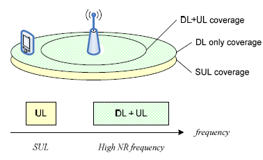
The basic idea behind this is as follows.
i) Usually cell coverage in UL direction is lower than DL direction because UE Tx Power(UL Power) is not as strong as gNB Tx Power(DL Power).
ii) The performance degradation on UL direction due to this difference gets very serious as the UE approaches to cell edge.
iii) As a possible solution, an idea to use very low frequency than the original UL frequency is proposed. As you know, cell coverage gets larger as frequency gets lower.
iv) this (to use a secondary UL at much lower frequency) is the idea behind SUL. When the channel condition is good, Network tell UE to use the original UL frequency and when channel condition gets poor than a certain criteria, Network directs UE to use the secondary(supplementary) UL frequency.
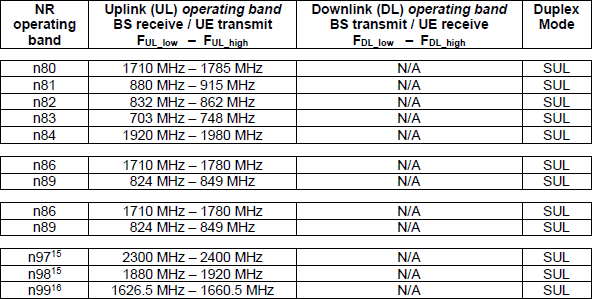
There are several NR bands dedicated for SUL which are n80, n81, n82, n83, n84, n86. As you see in this table, these are all under 2Ghz which is lower than commonly used NR frequency(e.g, over 3Ghz). However, one possible drawback of this approach is that these SUL bands are colliding with existing LTE bands. So it would cause NR-LTE Co Existance issues. You would need some researches on SUL and NR/LTE Coexistance issue before you make decision to deploy any SUL. See TR 37.872 and TR 37.716 for the details on SUL and NR/LTE CoExistance.
Would SUL be useful in real practice and widely deployed ? See this blog by Martin.
Overall Procedures
Overall procedure for SUL operation can be summarized in illustration shown below.
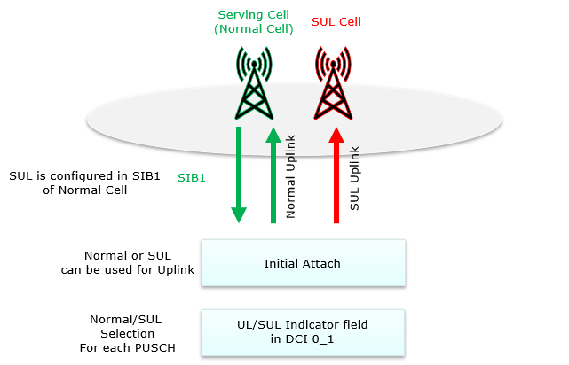
- Step 1 : SUL configuration is broadcast by SIB1 of Normal Cell
- Step 2 : UE trigger RACH to Normal Cell or SUL cell depending on signal condition it percieves and Completes the initial attach
- Step 3 : Once in Connection Mode. gNB can dynamically switching between Normal cell and SUL cell via DCI 0_1.
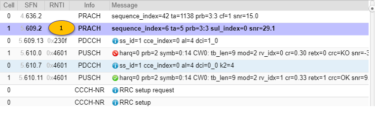
Example 01 > Following example is from the test with Amarisoft Callbox and UEsim
|
[1] PRACH : RACH to SUL Cell |
Message: sequence_index=0 ta=5 prb=3:3
|
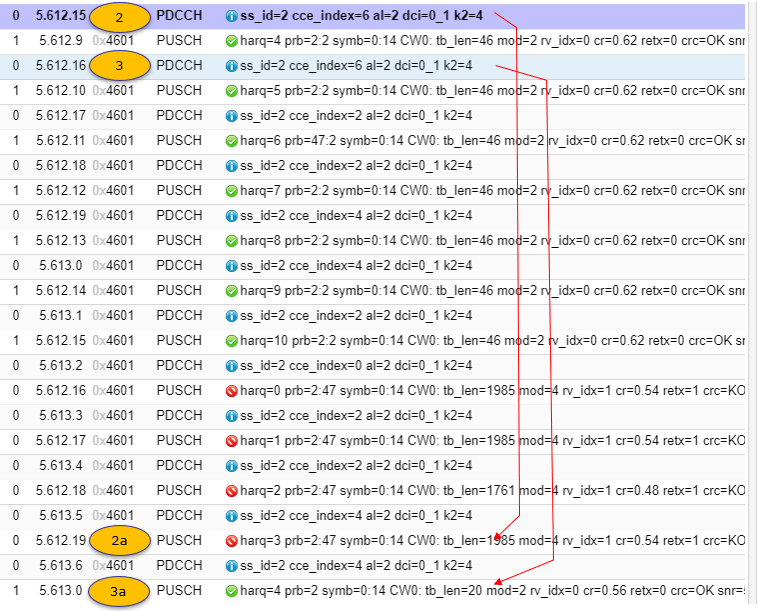
[2] PDCCH : Scheduling PUSCH on Normal Cell |
Message: ss_id=2 cce_index=6 al=2 dci=0_1 k2=4
Data:
rb_alloc=0x12f
mcs=14
ndi=0
rv_idx=1
harq_process=3
dai=3
tpc_command=1
antenna_ports=0
srs_request=0
dmrs_seq_init=0
ul_sch_indicator=1
|
[2a] PUSCH : on Normal Cell Nacked |
Message: harq=3 prb=2:47 symb=0:14 CW0: tb_len=1985 mod=4 rv_idx=1 cr=0.54 retx=1 crc=KO snr=3.0 epre=-43.4 ta=0.6
|
[3] PDCCH : Scheduling PUSCH on SUL Cell |
Message: ss_id=2 cce_index=6 al=2 dci=0_1 k2=4
Data:
rb_alloc=0x2
mcs=7
ndi=1
rv_idx=0
harq_process=4
dai=3
tpc_command=1
antenna_ports=0
srs_request=0
dmrs_seq_init=0
ul_sch_indicator=1
|
[3a] PUSCH : on SUL Cell : Acked |
Message: harq=4 prb=2 symb=0:14 CW0: tb_len=20 mod=2 rv_idx=0 cr=0.56 retx=0 crc=OK snr=5.2 epre=-24.6 ta=5.3
Operation Highlights
What I mentioned above is based on my intuitive understanding on SUL operation. In this section, I will quote some formal description from 3GPP specification for your (my) reference.
38.300 - 5.4.2 state as follows :
In conjunction with a UL/DL carrier pair (FDD band) or a bidirectional carrier (TDD band), a UE may be configured with additional, Supplementary Uplink (SUL).
38.300 - 6.9 state as follows :
In case of Supplementary Uplink,
38.300 - 9.2.6 state as follows :
For initial access in a cell configured with SUL,
38.300 - 10.3 state as follows :
38.213 - 8 states as follows :
If a UE is configured with two UL carriers for a serving cell and the UE detects a ,
38.321 - 5.1.1 states as follows :
if
else:
select the NUL carrier for performing Random Access procedure;
Band Combinations for SUL
Following is the frequency band assigned to SUL in 3GPP.
< 38.101-1 v17.5 - Table 5.2-1: NR operating bands in FR1 >
Followings are the table that I consolidated multiple tables from TR 37.872.
|
SUL Band combination |
NR Band |
Uplink (UL) band |
Downlink (DL) band |
Duplex mode |
||||
|
BS receive / UE transmit |
BS transmit / UE receive |
|||||||
|
FUL_low FUL_high |
FDL_low FDL_high |
|||||||
|
SUL_n78-n80 |
n78 |
3300 MHz |
3800 MHz |
3300 MHz |
3800 MHz |
TDD |
||
|
n80 |
1710 MHz |
1785 MHz |
SUL |
|||||
|
SUL_n79-n80 |
n79 |
4400 MHz |
5000 MHz |
4400 MHz |
5000 MHz |
TDD |
||
|
n80 |
1710 MHz |
1785 MHz |
SUL |
|||||
|
SUL_n78-n84 |
n78 |
3300 MHz |
3800 MHz |
3300 MHz |
3800 MHz |
TDD |
||
|
n84 |
1920 MHz |
1980 MHz |
N/A |
SUL |
||||
|
SUL_n78-n82 |
n78 |
3300 MHz |
3800 MHz |
3300 MHz |
3800 MHz |
TDD |
||
|
n82 |
832 MHz |
862 MHz |
N/A |
SUL |
||||
|
SUL_n78-n81 |
n78 |
3300 MHz |
3800 MHz |
3300 MHz |
3800 MHz |
TDD |
||
|
n81 |
880 MHz |
915 MHz |
N/A |
SUL |
||||
|
SUL_n78-n83 |
n78 |
3300 MHz |
3800 MHz |
3300 MHz |
3800 MHz |
TDD |
||
|
n83 |
703 MHz |
748 MHz |
N/A |
SUL |
||||
|
SUL_n78-n86 |
n78 |
3300 MHz |
3800 MHz |
3300 MHz |
3800 MHz |
TDD |
||
|
n86 |
1710 MHz |
1780 MHz |
N/A |
SUL |
||||
|
SUL_n79-n81 |
n79 |
4400 MHz |
5000 MHz |
4400 MHz |
5000 MHz |
TDD |
||
|
n81 |
880 MHz |
915 MHz |
N/A |
SUL |
||||
Following is the table for SUL with ENDC. You would notice that all LTE is FDD and all NR is TDD, and NR SUL is in same frequency range in LTE UL range implying that NR UL and LTE UL would share the frequency range.
|
E-UTRA and NR DC Band |
E-UTRA and NR Band |
Uplink (UL) band |
Downlink (DL) band |
Duplex mode |
||||
|
BS receive / UE transmit |
BS transmit / UE receive |
|||||||
|
FUL_low FUL_high |
FDL_low FDL_high |
|||||||
|
DC_3-SUL_n79-n80 |
3 |
1710 MHz |
1785 MHz |
1805 MHz |
1880 MHz |
FDD |
||
|
n79 |
4400 MHz |
5000 MHz |
4400 MHz |
5000 MHz |
TDD |
|||
|
n80 |
1710 MHz |
1785 MHz |
NA |
SUL |
||||
|
DC_1-SUL_n78-n84 |
1 |
1920 MHz |
1980 MHz |
2110 MHz |
2170 MHz |
FDD |
||
|
n78 |
3300 MHz |
3800 MHz |
3300 MHz |
3800 MHz |
TDD |
|||
|
n84 |
1920 MHz |
1980 MHz |
NA |
SUL |
||||
|
DC_20-SUL_n78-n82 |
20 |
832 MHz |
862 MHz |
791MHz |
821 MHz |
FDD |
||
|
n78 |
3300 MHz |
3800 MHz |
3300 MHz |
3800 MHz |
TDD |
|||
|
n82 |
832 MHz |
862 MHz |
NA |
SUL |
||||
|
DC_8-SUL_n78-n81 |
8 |
880 MHz |
915 MHz |
925 MHz |
960 MHz |
FDD |
||
|
n78 |
3300 MHz |
3800 MHz |
3300 MHz |
3800 MHz |
TDD |
|||
|
n81 |
880 MHz |
915 MHz |
N/A |
SUL |
||||
|
DC_28-SUL_n78-n83 |
28 |
703 MHz |
748 MHz |
758 MHz |
803 MHz |
FDD |
||
|
n78 |
3300 MHz |
3800 MHz |
3300 MHz |
3800 MHz |
TDD |
|||
|
n83 |
703 MHz |
748 MHz |
N/A |
SUL |
||||
|
DC_66-SUL_n78-n86 |
66 |
1710 MHz |
1780 MHz |
2110 MHz |
2200 MHz |
FDD |
||
|
n78 |
3300 MHz |
3800 MHz |
3300 MHz |
3800 MHz |
TDD |
|||
|
n86 |
1710 MHz |
1780 MHz |
N/A |
SUL |
||||
|
DC_8-SUL_n79-n81 |
8 |
880 MHz |
915 MHz |
925 MHz |
960 MHz |
FDD |
||
|
n79 |
4400 MHz |
5000 MHz |
4400 MHz |
5000 MHz |
TDD |
|||
|
n81 |
880 MHz |
915 MHz |
N/A |
SUL |
||||
|
DC_3-SUL_n78-n82 |
3 |
1710 MHz |
1785 MHz |
1805 MHz |
1880 MHz |
FDD |
||
|
n78 |
3300 MHz |
3800 MHz |
3300 MHz |
3800 MHz |
TDD |
|||
|
n82 |
832 MHz |
862 MHz |
N/A |
SUL |
||||
|
DC_20-SUL_n78-n83 |
20 |
832 MHz |
862 MHz |
791 MHz |
821 MHz |
FDD |
||
|
n78 |
3300 MHz |
3800 MHz |
3300 MHz |
3800 MHz |
TDD |
|||
|
n83 |
703 MHz |
748 MHz |
N/A |
SUL |
||||
Reference