5G Security mechanism is not completely new design comparing to 4G Security mechanism. But there are some differences and improvement in 5G in terms of security protection mechanism. 5G offers several improvements over 4G in terms of security, including stronger encryption, better authentication, and more flexibility in terms of network slicing and virtualization. However, as with any new technology, there are also new security risks that need to be addressed.
- 4G vs 5G Security
- 5G Authentication Process
- Key Hierarchy and Distribution
- AS Security Mode Command
- NAS Security Mode Command
- User Plane Security
- Key Handling in Handover
What is the problem with Previous Technology ?
It seems there is some degree of improvement in every new neneration of cellular communication. The improvement usually comes from compensating the issues in previous technology. I thought it would be good to briefly summarize on what kind of issues were there in previous technology.
2G:
Lack of mutual authentication : In 2G networks, Authentication is applied unilaterally. Network authenticate UE, but UE does not authenticate UE. So as long as network accept UE, UE does not complain anything and continue communication. In this case, it would be so each to use fake network to snatch UE.Weak encryption :: The encryption algorithm used in 2G networks is known as the A5/1 algorithm, which is susceptible to eavesdropping and interception attacks.Vulnerability to attacks :: 2G networks are vulnerable to attacks such as denial-of-service(DoS) attacks, man-in-the-middle attacks, and SMS interception.==> for example, by using non-authenticated device you can do various types of DoS attack like Signaling Storm, SMS Flooding, Resource Starvation)
3G:
Vulnerability to attacks :: 3G networks are also vulnerable to denial-of-service attacks, man-in-the-middle attacks, and SMS interception.Weaknesses in encryption :: 3G networks use the KASUMI encryption algorithm, which has been found to have vulnerabilities that can be exploited by attackers.No NAS Integrity : : As far as I recall, in 3G we only have protections for RRC message via RRC Security Mode Command, but no NAS integrity protection.
4G:
Vulnerability to attacks : 4G networks are vulnerable to attacks such as denial-of-service attacks, man-in-the-middle attacks, and SMS interception.Lack of end-to-end encryption : 4G networks use stronger encryption algorithms than previous generations but they do not provide end-to-end encryption, which means that data can still be intercepted by attackers.Security of signaling messages : The signaling messages used in 4G networks are not always authenticated, which leaves the network vulnerable to attacks such as fake base station attacks.NOTE : As you know, in 4G NAS integrity is introduced and resolved the issue of 'No NAS Integrity'.NOTE : Example of Vulnearbility (Source : Why 5G Can Be More Secure Than 4G ) - When a 4G phone connects to a base station, it authenticates the users identity, but does sowithout encrypting the information , leaving it vulnerable to attack. So although any subsequent calls or texts are encrypted in 4G,the users identity and location are not (encrypted) . 5G uses256-bit encryption, a substantial improvement on the 128-bit standard used by 4G .. With 5G, the users identity and location are encrypted, making them impossible to identify or locate from the moment they get on the network.
4G vs 5G Security
The comparison between 4G and 5G security highlights significant advancements in 5G, driven by the need to address 4G’s vulnerabilities and support a broader range of applications, such as IoT and critical infrastructure. 5G introduces enhanced user authentication and stronger data authentication through new protocols like 5G-AKA, EAP-AKA', and EAP-TLS, which improve upon 4G’s EPS-AKA. Key improvements include better privacy with encrypted identifiers (SUCI), support for public key cryptography, a more distributed security architecture with entities like SEAF and AUSF, and modern communication protocols like HTTP-based APIs. These changes make 5G more secure, scalable, and adaptable to modern threats and use cases.
Enhanced User Authentication : 5G significantly improves user authentication by introducing more robust and flexible mechanisms to verify the identity of devices and users. Unlike 4G, which relies solely on the EPS-AKA protocol using a shared symmetric key, 5G offers multiple authentication methods, including 5G-AKA, EAP-AKA', and EAP-TLS. The latter introduces public key cryptography, allowing certificate-based authentication that eliminates the risks associated with symmetric key distribution, such as key compromise. Additionally, 5G enhances privacy through the use of SUCI (Subscription Concealed Identifier), which encrypts the user’s permanent identifier (SUPI), preventing exposure during transmission—a major improvement over 4G’s IMSI, which was vulnerable to interception by IMSI catchers. The involvement of the home network (via the AUSF) in authentication decisions further ensures greater oversight and accountability, reducing the risk of fraudulent access in roaming scenarios.Stronger Data Authentication : 5G strengthens data authentication by implementing more secure mechanisms to ensure the integrity and authenticity of data exchanged between network entities. While 4G uses NAS (Non-Access Stratum) and Diameter protocols for communication, 5G adopts modern HTTP-based web APIs for interactions between the serving and home networks, offering better security through HTTPS and improved interoperability. The introduction of a more granular key hierarchy in 5G, with AscendingList with keys like KSEAF and KAUSF, provides better key separation, reducing the impact of a compromised key compared to 4G’s simpler KASME-based hierarchy. Furthermore, 5G’s support for public key cryptography in EAP-TLS ensures stronger data integrity, as certificates are harder to forge than symmetric keys. These enhancements collectively make data in 5G networks more resistant to tampering and unauthorized access, addressing vulnerabilities in 4G that could lead to data breaches or manipulation.
Authentication Protocols in 5G
Authentication protocols in mobile networks have evolved significantly from 4G to 5G to address security challenges and support diverse use cases. In 4G LTE networks, the EPS-AKA (Evolved Packet System-Authentication and Key Agreement) protocol serves as the standard for authenticating users and establishing secure communication using a shared symmetric key. 5G introduces more advanced protocols, with 5G-AKA as the primary method, building on EPS-AKA to enhance security and privacy while maintaining compatibility. Additionally, 5G supports EAP-AKA', an extensible authentication protocol variant often used for non-3GPP access like Wi-Fi, and EAP-TLS, a certificate-based protocol that leverages public key cryptography to provide stronger security, particularly for scenarios requiring higher trust and integrity. These advancements in 5G authentication protocols ensure greater flexibility, privacy, and resilience against modern threats compared to 4G.
- EPS-AKA (4G): The authentication and key agreement protocol used in 4G LTE networks.
- 5G-AKA: The primary authentication protocol for 5G, an evolution of EPS-AKA.
- EAP-AKA': An extensible authentication protocol variant used in 5G, often for non-3GPP access (e.g., Wi-Fi).
- EAP-TLS: A certificate-based authentication protocol used in 5G, providing stronger security through public key cryptography.
Why These Changes Matter
The improvements in 5G security are driven by the need to address 4G’s vulnerabilities and support 5G’s broader use cases (e.g., IoT, critical infrastructure, ultra-low latency applications). Here’s why each change is significant:
- Privacy (SUCI): 4G’s IMSI exposure was a major privacy risk, exploited by IMSI catchers. 5G’s SUCI ensures the permanent identifier is encrypted, protecting user privacy.
- Flexibility (EAP-TLS): By supporting public key cryptography, 5G can securely authenticate a wider range of devices, including those without SIMs, which is critical for IoT.
- Distributed Security (SEAF, AUSF): 5G’s architecture distributes security functions, reducing single points of failure and improving resilience.
- Home Network Involvement: Involving the home network in authentication decisions ensures better oversight and accountability, addressing potential fraud in roaming scenarios.
- Modern Protocols (HTTP APIs): Moving away from Diameter to HTTP-based APIs aligns 5G with modern standards, improving interoperability and security.
Comparative Table between 4G and 5G
The comparison table between 4G and 5G security provides a high-level overview of the advancements in 5G, focusing on key areas such as entities involved, message formats, trust models, identity management, authentication processes, and key hierarchies. It contrasts 4G’s EPS-AKA protocol with 5G’s authentication methods—5G-AKA, EAP-AKA', and EAP-TLS—highlighting how 5G improves user and data authentication through enhanced privacy, modern protocols, and more robust cryptographic mechanisms, making it better suited for diverse and demanding applications like IoT and critical infrastructure.
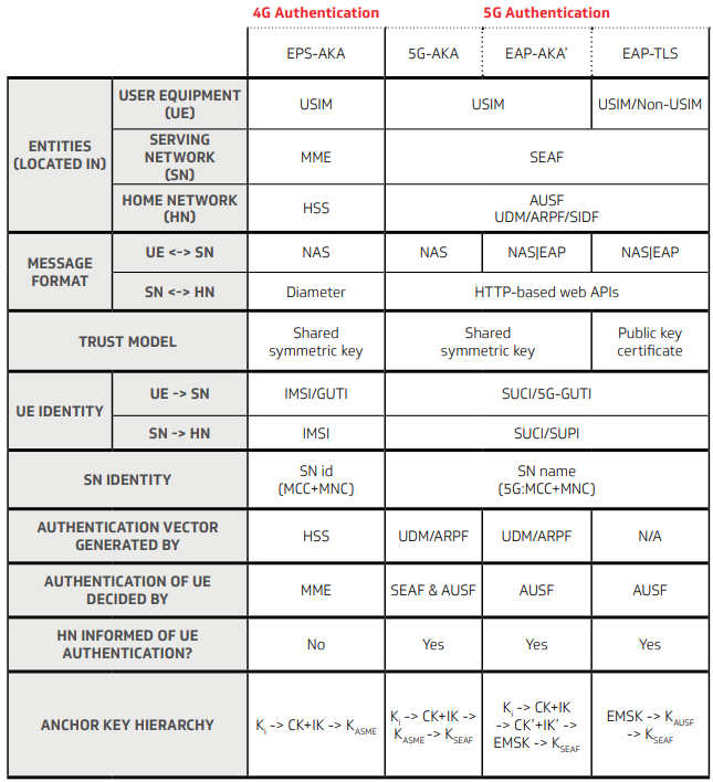
Source : 4G vs 5G Security, The Key Differences - CableLabs
Followings are breakdown of the table and description. It is just verbalized form of the table.
This row identifies the network entities involved in authentication and their roles in 4G and 5G networks.
-
User Equipment (UE): 5G’s support for non-USIM in EAP-TLS allows a broader range of devices to connect securely, which is crucial for the diverse ecosystem of 5G (e.g., IoT, industrial applications).
-
4G (EPS-AKA): The UE uses a USIM (Universal Subscriber Identity Module), which stores the subscriber’s credentials.
-
5G (5G-AKA, EAP-AKA'): The UE also uses a USIM.
-
5G (EAP-TLS): The UE can use either a USIM or a non-USIM (e.g., a certificate-based credential), providing flexibility for devices like IoT that may not have a traditional SIM.
-
Serving Network (SN): The SEAF in 5G is a dedicated security entity, improving the separation of concerns and making the architecture more resilient to attacks targeting mobility management.
-
4G: The MME (Mobility Management Entity) handles authentication and session management in the serving network.
-
5G: The SEAF (Security Anchor Function) takes over this role, separating security functions from mobility management for better modularity.
-
Home Network (HN): 5G splits the HSS’s responsibilities into specialized functions (AUSF, UDM, etc.), improving scalability and security. The SIDF, for example, ensures that encrypted identifiers can be securely processed, enhancing privacy.
-
4G: The HSS (Home Subscriber Server) manages subscriber data and generates authentication vectors.
-
5G: The AUSF (Authentication Server Function) and UDM/ARPF/SIDF (Unified Data Management/Authentication Credential Repository and Processing Function/Subscription Identifier De-concealing Function) handle these tasks. The UDM stores subscriber data, the ARPF generates authentication vectors, and the SIDF de-conceals encrypted identifiers (SUCI).
This row describes the protocols used for communication between entities.
-
UE ↔ SN: The use of EAP in 5G (for EAP-AKA' and EAP-TLS) allows for more flexible authentication methods, supporting both SIM-based and certificate-based authentication.
-
4G: Uses NAS (Non-Access Stratum) protocol for signaling between the UE and the serving network.
-
5G (5G-AKA, EAP-AKA'): Also uses NAS, maintaining compatibility with 4G.
-
5G (EAP-TLS): Uses NAS/EAP, where EAP (Extensible Authentication Protocol) messages are encapsulated within NAS.
-
SN ↔ HN: HTTP-based APIs in 5G are more aligned with modern web standards, offering better interoperability, scalability, and security (e.g., through HTTPS). Diameter, while functional, is less efficient and harder to secure in modern contexts.
-
4G: Uses the Diameter protocol, a legacy protocol for authentication, authorization, and accounting (AAA).
-
5G: Uses HTTP-based web APIs, a more modern and flexible approach.
This row describes the cryptographic foundation of authentication. Symmetric key systems (used in 4G and 5G-AKA/EAP-AKA') rely on securely distributing and storing the shared key, which can be a vulnerability if the key is compromised. EAP-TLS’s public key cryptography eliminates this risk by using certificates, which are harder to forge and don’t require pre-shared secrets. This makes EAP-TLS more secure, especially for non-3GPP access (e.g., Wi-Fi).
-
4G (EPS-AKA): Uses a shared symmetric key (K) stored in the USIM and HSS.
-
5G (5G-AKA, EAP-AKA'): Also uses a shared symmetric key, maintaining compatibility with 4G.
-
5G (EAP-TLS): Uses a public key certificate, where the UE and network authenticate using public/private key pairs.
This row explains how the UE identifies itself to the network. 5G’s use of SUCI addresses a major privacy flaw in 4G, where IMSI catchers (fake base stations) could intercept the IMSI and track users. By encrypting the SUPI into a SUCI, 5G ensures that the permanent identifier is protected during transmission, significantly enhancing user privacy.
-
UE → SN:
-
4G: Uses IMSI (International Mobile Subscriber Identity) or GUTI (Globally Unique Temporary Identifier). The IMSI is a permanent identifier, and its exposure in plaintext can lead to privacy issues (e.g., tracking).
-
5G: Uses SUCI (Subscription Concealed Identifier) or 5G-GUTI. The SUCI encrypts the SUPI (Subscription Permanent Identifier, the 5G equivalent of IMSI) using the home network’s public key, ensuring the permanent identifier is never exposed in plaintext.
-
SN → HN:
-
4G: Sends the IMSI to the home network.
-
5G: Sends the SUCI or SUPI (after de-concealing the SUCI using the SIDF).
This row describes how the serving network identifies itself. The change is mostly syntactic, but the explicit “SN name” in 5G aligns with its service-based architecture, where entities are identified in a more standardized way.
-
4G: Uses an SN ID (MCC+MNC, Mobile Country Code + Mobile Network Code).
-
5G: Uses an SN name (5G:MCC+MNC), a slight reformatting for clarity.
This row explains which entity generates the authentication vectors (sets of cryptographic values used to authenticate the UE). In 5G, the UDM/ARPF takes over the role of generating authentication vectors, aligning with the new architecture. EAP-TLS skips this step entirely, as it relies on certificate-based authentication, which doesn’t require pre-generated vectors.
-
4G: The HSS generates the authentication vector.
-
5G (5G-AKA, EAP-AKA'): The UDM/ARPF generates it.
-
5G (EAP-TLS): Not applicable (N/A), as EAP-TLS uses certificates instead of authentication vectors.
This row indicates which entity decides if the UE is authenticated. In 4G, the MME (in the serving network) has full control over authentication, which can be a point of failure if the serving network is compromised. 5G distributes this responsibility (in 5G-AKA) or shifts it to the home network (in EAP-AKA' and EAP-TLS), reducing the risk of a compromised serving network affecting authentication.
-
4G: The MME decides.
-
5G (5G-AKA): Both the SEAF and AUSF decide, involving both the serving and home networks.
-
5G (EAP-AKA', EAP-TLS): The AUSF decides, centralizing the decision in the home network.
This row checks if the home network is informed of the UE’s authentication status. In 4G, the lack of home network involvement means it has no visibility into whether the UE was successfully authenticated, limiting accountability. 5G ensures the home network (via the AUSF) is aware, improving oversight and enabling better detection of fraudulent activity.
-
4G: No, the HSS is not informed.
-
5G: Yes, the AUSF is informed in all 5G methods.
This row describes the hierarchy of keys used to secure communication. 5G introduces a more granular key hierarchy, with separate keys for the SEAF and AUSF, improving key separation and reducing the impact of a compromised key. EAP-TLS's use of EMSK aligns with its certificate-based approach, providing a stronger cryptographic foundation.
- 4G (EPS-AKA): K → CK + IK → KASME
- K: The shared symmetric key.
- CK + IK: Cipher Key and Integrity Key, derived from K.
- KASME: The anchor key for the MME, derived from CK + IK.
- 5G (5G-AKA, EAP-AKA'): K → CK + IK → KSEAF → KAUSF
- K, CK + IK: Same as 4G.
- KSEAF: The anchor key for the SEAF, derived from CK + IK.
- KAUSF: A higher-level key for the AUSF, derived from KSEAF.
- 5G (EAP-TLS): EMSK → KAUSF → KSEAF
- EMSK: Extended Master Session Key, derived during EAP-TLS authentication.
- KAUSF, KSEAF: Derived in a similar hierarchy but rooted in the EMSK.
5G Authentication Process
The 5G-AKA authentication process ensures mutual authentication: the UE verifies the network’s authenticity (via AUTN), and the network verifies the UE (via RES* comparison). It also establishes the anchor key K_SEAF for secure communication. The use of SUCI/SUPI protects user privacy, and the distributed roles of SEAF, AUSF, and UDM/ARPF enhance security by separating responsibilities across the network. This process is more robust than 4G’s EPS-AKA, with better privacy and key derivation mechanisms.
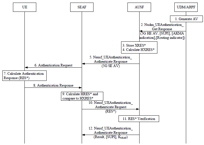
The diagram below illustrates the 5G authentication process using the 5G-AKA (Authentication and Key Agreement) protocol. It outlines the steps and interactions between four key entities in a 5G network: the User Equipment (UE), the Security Anchor Function (SEAF), the Authentication Server Function (AUSF), and the Unified Data Management/Authentication Credential Repository and Processing Function (UDM/ARPF). The process ensures mutual authentication between the UE and the network, establishes shared keys for secure communication, and protects user privacy through encrypted identifiers.
< 33.501-Figure 6.1.3.2-1: Authentication procedure for 5G AKA >
-
Generate AV (UDM/ARPF): The UDM/ARPF generates an Authentication Vector (AV), which includes cryptographic values like the expected response (XRES*), a key (K_AUSF), and other parameters needed for authentication.
-
Nudm_UEAuthentication_Get Response (AUSF to UDM/ARPF): The AUSF requests the AV from the UDM/ARPF, providing the UE’s Subscription Concealed Identifier (SUCI) or Globally Unique Temporary Identifier (5G-GUTI), along with an Authentication and Key Management for Applications (AKMA) indication and routing indicator. The UDM/ARPF responds with the AV, including the 5G Home Environment Authentication Vector (5G HE AV).
-
Store XRES (AUSF): The AUSF stores the expected response (XRES) from the AV, which will later be used to verify the UE’s response.
-
Calculate HXRES (AUSF): The AUSF calculates the Hash of the Expected Response (HXRES), a value derived from XRES*, which the SEAF will use to verify the UE’s authenticity without directly handling XRES*.
-
Nausf_UEAuthentication_Authenticate Response (AUSF to SEAF): The AUSF sends the 5G Serving Environment Authentication Vector (5G SE AV) to the SEAF, which includes HXRES* and other parameters needed for the authentication challenge.
-
Authentication Request (SEAF to UE): The SEAF sends an authentication request to the UE, containing the challenge (e.g., a random number RAND and authentication token AUTN) derived from the 5G SE AV.
-
Calculate Authentication Response (RES) (UE): The UE uses its shared key (K) stored in the USIM to calculate the authentication response (RES) based on the challenge received from the SEAF. It also verifies the network’s authenticity using the AUTN.
-
Authentication Response (UE to SEAF): The UE sends the calculated RES* back to the SEAF as part of the authentication response.
-
Calculate HXRES and Compare to HXRES (SEAF): The SEAF calculates the Hash of the Received Response (HXRES*) from the UE’s RES* and compares it with the HXRES* received from the AUSF to verify the UE’s authenticity.
-
Nausf_UEAuthentication_Authenticate Request (SEAF to AUSF): The SEAF forwards the UE’s RES* to the AUSF for final verification.
-
RES Verification (AUSF): The AUSF compares the UE’s RES with the stored XRES*. If they match, the UE is authenticated, and the AUSF derives the anchor key K_SEAF.
-
Nausf_UEAuthentication_Authenticate Response (AUSF to SEAF): The AUSF sends the authentication result to the SEAF, including the UE’s Subscription Permanent Identifier (SUPI) if the SUCI was used, and the derived K_SEAF, which the SEAF will use to secure further communication with the UE.
Key Hierarchy and Distribution
Key hierarchy and distribution in 5G are fundamental to ensuring secure communication, authentication, and data integrity across the network. The system follows a structured and hierarchical key derivation mechanism, where a root key, stored securely in the USIM, serves as the foundation for generating multiple security keys. These keys are derived and distributed across various network entities, including the Authentication Server Function (AUSF), Security Anchor Function (SEAF), Access and Mobility Management Function (AMF), and the gNB, ensuring that each layer of the network has the necessary cryptographic protections. The hierarchical nature of the key system ensures that if a lower-level key is compromised, the root key remains protected, preventing unauthorized access to higher-level security mechanisms. Additionally, this layered approach allows efficient key updates and re-authentication processes while minimizing key exposure, thus enhancing the overall security of 5G communications. With the use of advanced key derivation functions (KDFs), secure key separation, and context-based key generation, 5G provides a more resilient and robust security framework compared to previous generations of mobile networks.
Key Management Overview
In the 5G security architecture, key management is a carefully orchestrated process distributed across different network functions. The core of this system involves a clear division of responsibility between the radio and core networks. The Access and Mobility Management Function (AMF), a core network entity, directly manages the Non-Access Stratum (NAS) security keys, which protect the signaling link between the user's device and the core. While the gNB is responsible for deriving the Access Stratum (AS) keys to secure the radio interface, it cannot do so independently. This process is initiated by the AMF, which provides the gNB with a crucial base key, KgNB. This entire key hierarchy originates during the primary authentication procedure, where functions like the Authentication Server Function (AUSF) and the Security Anchor Function (SEAF) generate the initial high-level keys that the AMF subsequently uses to secure the connection.
- NAS Security Keys: Managed primarily by the AMF.
- AS Security Keys: Derived by the gNB, but initiated by the AMF providing the necessary base key (KgNB).
- Other core network entities, like the AUSF (Authentication Server Function) and SEAF (Security Anchor Function), are involved in generating higher-level keys during authentication, which are then used by the AMF.
Roles of Network Entities in Key Management
In 5G networks, the management of security keys is a detailed and hierarchical process, with distinct roles assigned to each network function to ensure a robust, end-to-end security framework. This process begins with the AUSF handling the primary authentication procedure, which generates an intermediate key that is passed to the SEAF. Acting as the security anchor, the SEAF uses this to derive the anchor key, K_SEAF, which is then provided to the AMF. The AMF holds a central role, managing all NAS security by deriving integrity and encryption keys from K_AMF and also kickstarting AS security. It does this by deriving the crucial base key, KgNB, and forwarding it along with the UE's security capabilities to the gNB. Finally, the gNB takes on the responsibility for the radio interface, using the received KgNB to derive a full suite of keys for RRC and user plane protection, and then activating this security with the UE. This clear separation of duties, from the long-term key storage in the UDM to the final key derivation in the gNB, ensures a secure and coordinated activation of both NAS and AS protection.
AMF (Access and Mobility Management Function):
- Primary Role in NAS Security:Manages NAS security keys: K_NASint (for integrity protection) and K_NASenc (for encryption).
- Derives these keys from K_AMF, which is generated during the primary authentication process.
- Triggers the NAS Security Mode Command (SMC) procedure to activate NAS security with the UE, selecting appropriate algorithms based on UE Security Capabilities.
- Role in AS Security:
- Provides the KgNB (base key for AS security) to the gNB via the NGAP INITIAL CONTEXT SETUP REQUEST message.
- KgNB is derived from K_AMF after successful primary authentication or NAS SMC completion.
- Forwards UE Security Capabilities to the gNB, enabling it to select AS algorithms (e.g., NIA1-3 for integrity, NEA1-3 for encryption).
- The AMF ensures coordination between NAS and AS security activation.
AUSF (Authentication Server Function):
- Handles primary authentication (e.g., 5G-AKA or EAP-AKA') with the UE.
- Generates the K_AUSF key during authentication, which is used as an intermediate key.
- Passes K_AUSF to the SEAF for further processing.
SEAF (Security Anchor Function):
- Often co-located with the AMF in 5G deployments.
- Derives K_SEAF from K_AUSF during authentication.
- Passes K_SEAF to the AMF, which then derives K_AMF.
- The SEAF acts as the anchor for the authentication process, ensuring the UE and network mutually authenticate.
UDM (Unified Data Management) / ARPF (Authentication Credential Repository and Processing Function):
- Stores the long-term key K (shared secret between UE and network) and authentication vectors.
- Generates authentication vectors during primary authentication, which are used by the AUSF and SEAF.
gNB (Next Generation NodeB):Responsible for AS security key derivation:
- Uses KgNB (received from AMF) to derive K_RRCint (RRC integrity), K_RRCenc (RRC encryption), K_UPint (user plane integrity), and K_UPenc (user plane encryption).
- Selects AS algorithms based on UE Security Capabilities provided by the AMF.
- Triggers the RRC Security Mode Command to activate AS security with the UE.
- While the gNB derives AS keys, it relies on the AMF to provide the KgNB and initiate the process.
Overview of Key Derivation Flow
In 5G, the security key derivation follows a distinct hierarchical flow, cascading from the core network down to the radio equipment. The process begins during primary authentication, where a long-term secret key, K, stored in the UDM, is used by the AUSF and SEAF to generate an anchor key, K_SEAF. This key is then passed to the AMF, which derives its own master key, K_AMF. From this single point, the AMF orchestrates two parallel security activations: it derives the NAS integrity and encryption keys to secure signaling with the core network, and it derives the base key for the radio, K_gNB. Finally, the AMF provides this K_gNB to the gNB, which then uses it to derive all the necessary AS keys for protecting traffic over the radio interface, completing the chain of trust from the core to the airwaves.
Primary Authentication: - UDM/ARPF → AUSF → SEAF: Generates K → K_AUSF → K_SEAF.
- SEAF → AMF: Provides K_SEAF, from which AMF derives K_AMF.
NAS Security: - AMF derives K_NASint and K_NASenc from K_AMF.
- AMF runs NAS SMC to activate NAS security.
AS Security: - AMF derives KgNB from K_AMF and sends it to the gNB (via INITIAL CONTEXT SETUP REQUEST).
- gNB derives AS keys (K_RRCint, K_RRCenc, etc.) and runs RRC SMC.
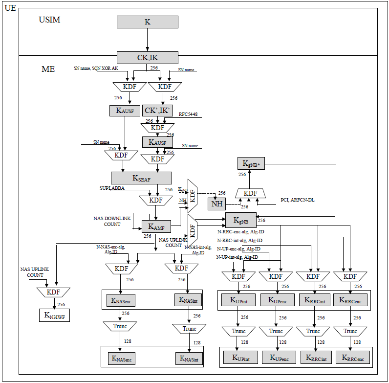
Key hierarchy generation
The 5G key hierarchy is more granular than 4G’s, with separate keys for NAS, RRC, and user plane security, as well as for 3GPP and non-3GPP access. This improves security by limiting the impact of a compromised key. The inclusion of K_AUSF and K_SEAF provides better key separation between the home and serving networks, enhancing security in roaming scenarios. The support for both 5G-AKA and EAP-AKA' ensures flexibility for different authentication methods, while the derivation of user plane keys (K_UPint, K_UPenc) adds an extra layer of security for data traffic, which was optional in 4G. Overall, this hierarchy ensures robust, layered security for 5G communications.
< 33.501 - Figure 6.2.1-1: Key hierarchy generation in 5GS >
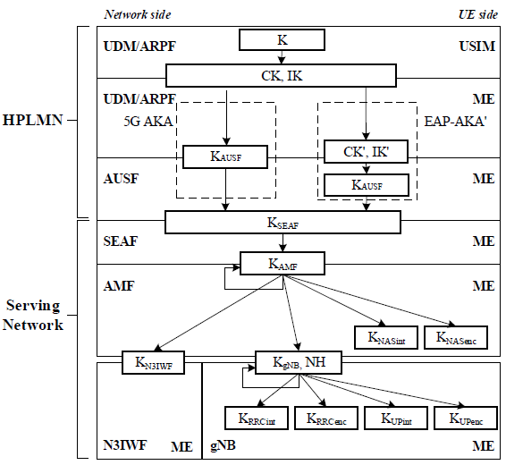
The diagram is divided into two sides: the Network side (HPLMN and Serving Network) and the UE side, showing how keys are derived and shared between entities like the UDM/ARPF, AUSF, SEAF, AMF, N3IWF, and the UE (via USIM and ME, Mobile Equipment). The process starts with a root key and progresses through multiple derivations to create keys for specific purposes, ensuring key separation and security.
- UDM/ARPF (HPLMN):
- K: The root key, a long-term shared symmetric key stored in the UDM/ARPF and the UE’s USIM.
- CK, IK (Cipher Key, Integrity Key): Derived from K during the 5G-AKA authentication process. These keys are used to derive further keys.
- AUSF (HPLMN):
- CK', IK': Modified versions of CK and IK, derived during EAP-AKA' authentication (if used instead of 5G-AKA).
- K_AUSF: Derived from CK, IK (or CK', IK' in EAP-AKA'). This is the anchor key for the AUSF, stored in the AUSF and passed to the UE side.
- SEAF (Serving Network):
- K_SEAF: Derived from K_AUSF by the AUSF and sent to the SEAF. This key serves as the anchor key for the serving network, ensuring secure communication between the UE and the serving network.
- AMF (Serving Network):
- K_AMF: Derived from K_SEAF by the SEAF and sent to the AMF (Access and Mobility Management Function). This key is used to derive lower-level keys for specific purposes.
- Lower-Level Keys (Derived from K_AMF):
- K_N3IWF: Derived for the N3IWF (Non-3GPP Interworking Function), used for non-3GPP access (e.g., Wi-Fi).
- K_gNB: Derived for the gNB (5G base station), used to secure communication between the UE and the gNB.
- K_NASint: Derived for NAS (Non-Access Stratum) integrity protection.
- K_NASenc: Derived for NAS encryption.
- K_RRCint: Derived for RRC (Radio Resource Control) integrity protection at the gNB.
- K_RRCenc: Derived for RRC encryption at the gNB.
- K_UPint: Derived for user plane integrity protection.
- K_UPenc: Derived for user plane encryption.
- USIM:
- K: The same root key as in the UDM/ARPF, stored securely in the USIM.
- CK, IK: Derived from K during 5G-AKA authentication, matching the network side.
- ME (Mobile Equipment):
- CK', IK': Derived during EAP-AKA' (if used).
- K_AUSF: Derived from CK, IK (or CK', IK'), matching the AUSF’s K_AUSF.
- K_SEAF: Derived from K_AUSF, matching the SEAF’s K_SEAF.
- K_AMF: Derived from K_SEAF, matching the AMF’s K_AMF.
- Lower-Level Keys: The ME derives the same set of keys as the network side (K_N3IWF, K_gNB, K_NASint, K_NASenc, K_RRCint, K_RRCenc, K_UPint, K_UPenc), ensuring both sides can encrypt and integrity-protect communication at various layers (NAS, RRC, and user plane).
Key distribution and key derivation scheme for 5G for network nodes
Key derivation and key distribution are fundamental security mechanisms used in communication systems like 5G to ensure secure authentication, encryption, and data integrity.
Key derivation is the process of generating cryptographic keys from an initial secret, often referred to as a master key or root key. Instead of using a single key for all security functions, the system derives multiple keys for different purposes, such as authentication, encryption, and integrity protection. This hierarchical approach enhances security by limiting the exposure of the master key while ensuring that different parts of the network use separate keys for specific tasks.
Key distribution refers to the secure transfer and management of these derived keys across various network nodes and entities. In a system like 5G, once the keys are derived at the authentication center (UDM/ARPF), they are securely distributed to relevant components such as AUSF, SEAF, AMF, and gNB. Each entity receives only the necessary keys required for its specific role. For example, the serving network (SEAF) gets the anchor key, while the access network (gNB) receives encryption and integrity protection keys.
Together, key derivation and distribution ensure that sensitive information remains protected throughout the communication process. By implementing a structured hierarchy of keys, security is maintained even if one key is compromised, as it does not expose higher-level or unrelated security credentials.
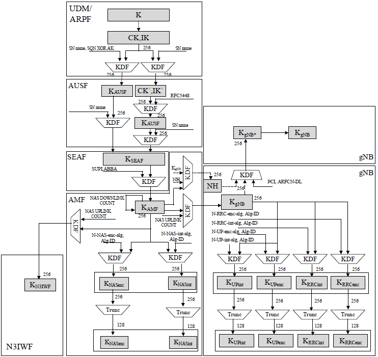
The diagram shown below illustrates the key distribution and derivation scheme in 5G. It depicts how cryptographic keys are generated and securely distributed among different network entities to ensure authentication, encryption, and integrity protection.
At the highest level, the UDM/ARPF (Unified Data Management / Authentication Credential Repository and Processing Function) holds the primary key K, which is used to derive authentication vectors. Using a key derivation function (KDF), it generates CK, IK (Cipher Key and Integrity Key) and further derives the KAUSF key, which is transferred to the AUSF (Authentication Server Function). The AUSF processes this key and passes it down to the SEAF (Security Anchor Function) after further derivation.
The SEAF then derives the KSEAF key, which is the main security anchor at the serving network. From this, the AMF (Access and Mobility Management Function) generates KAMF, which forms the basis for various security functions such as NAS encryption and integrity protection. The AMF derives KNASenc and KNASint, which are responsible for securing NAS layer communication between the UE and the core network.
For radio link security, the gNB (next-generation NodeB) derives KgNB, used for securing RRC and UP transmissions. From KgNB, additional keys are derived for RRC integrity protection (KRRCint), RRC encryption (KRRCenc), UP encryption (KUPenc), and UP integrity protection (KUPint).
For non-3GPP interworking, a separate key KN3IWF is generated, ensuring secure integration with untrusted non-3GPP access networks.
Overall, the 5G security framework introduces hierarchical key derivation, improving security by ensuring that different network functions operate with their own specialized keys while maintaining a strong authentication chain from the UDM/ARPF down to the gNB.
< 33.501 - Figure 6.2.2-1: Key distribution and key derivation scheme for 5G for network nodes >
Key distribution and key derivation scheme for 5G for the UE
The diagram shown below illustrates the key distribution and key derivation scheme for 5G within UE,. It details how cryptographic keys are derived and securely distributed within the UE to ensure authentication, encryption, and integrity protection.
At the core of the system, the USIM (Universal Subscriber Identity Module) holds the primary K key, which serves as the root of the security framework. The Mobile Equipment (ME) utilizes this key to generate CK (Cipher Key) and IK (Integrity Key) via a Key Derivation Function (KDF). These keys are then used to derive additional keys required for different security processes.
The next step involves the generation of KAUSF, which is used for authentication with the Authentication Server Function (AUSF) in the core network. After authentication, the system derives KSEAF, which serves as the anchor key for further security mechanisms in the Serving Network (SEAF).
Once the UE establishes communication, KAMF is derived from KSEAF and is responsible for securing NAS (Non-Access Stratum) messages. It further derives KNASenc for NAS encryption and KNASint for NAS integrity protection, ensuring secure exchanges between the UE and the core network.
For radio link security, KgNB is derived, which serves as the main key for access network protection. From KgNB, additional keys are derived for different security purposes:
- KRRCenc: Protects the confidentiality of RRC (Radio Resource Control) messages.
- KRRCint: Ensures the integrity of RRC messages.
- KUPenc: Encrypts user-plane data.
- KUPint: Provides integrity protection for user-plane transmissions.
For non-3GPP interworking, a separate key KN3IWF is derived to secure communication over non-trusted access networks.
The hierarchical key derivation structure ensures that each layer of security is built upon a previous level, minimizing key exposure and enhancing overall security. If a lower-level key is compromised, the root key K remains protected, maintaining the integrity of the authentication and encryption processes.
< 33.501 - Figure 6.2.2-2: Key distribution and key derivation scheme for 5G for the UE >
AS Security Mode Command
The AS (Access Stratum) Security Mode Command in 5G is a critical procedure that ensures secure communication between the UE and the gNB (next-generation NodeB) by activating encryption and integrity protection for both signaling and user data. This procedure is initiated by the gNB after the successful establishment of a secure connection and is used to negotiate and apply security algorithms for RRC (Radio Resource Control) and UP (User Plane) traffic. The Security Mode Command message sent by the gNB includes the selected encryption and integrity protection algorithms, which the UE must acknowledge and confirm before security settings take effect. The process also prevents security breaches by ensuring that all messages exchanged between the UE and the network are protected against eavesdropping and tampering. By implementing robust cryptographic protections and ensuring mutual agreement on security parameters, the AS Security Mode Command plays a crucial role in maintaining the confidentiality, integrity, and reliability of 5G network communications.
The following diagram illustrates the AS (Access Stratum) Security Mode Command procedure in 5G networks, detailing the steps to establish security between the User Equipment (UE) and the gNB/ng-eNB (5G base station). The process ensures that RRC (Radio Resource Control) signaling and user plane data are protected through integrity and ciphering mechanisms.
< 33.501 - Figure 6.7.4-1: AS Security Mode Command Procedure >
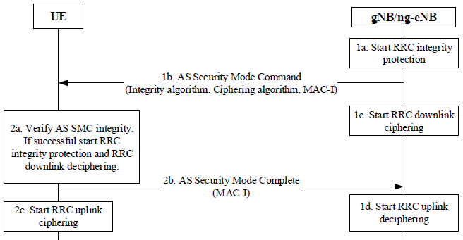
Below is an explanation of the steps involved:
-
gNB/ng-eNB Initiates Security: -
1a. Start RRC Integrity Protection: The gNB/ng-eNB begins integrity protection for RRC signaling using the derived key K_RRCint (from the key hierarchy). This ensures that RRC messages cannot be tampered with.
-
1b. AS Security Mode Command: The gNB/ng-eNB sends an AS Security Mode Command to the UE, specifying the integrity algorithm, ciphering algorithm, and a Message Authentication Code for Integrity (MAC-I). The MAC-I is generated using K_RRCint to allow the UE to verify the message’s integrity.
-
1c. Start RRC Downlink Ciphering: The gNB/ng-eNB starts ciphering RRC downlink messages using the derived key K_RRCenc, ensuring confidentiality of the communication from the gNB/ng-eNB to the UE.
-
UE Processes the Command: -
2a. Verify AS SMC Integrity: The UE verifies the integrity of the AS Security Mode Command by checking the MAC-I using its own K_RRCint. If the verification is successful, the UE starts RRC integrity protection (using K_RRCint) and downlink deciphering (using K_RRCenc) to process encrypted messages from the gNB/ng-eNB.
-
2b. AS Security Mode Complete: The UE responds with an AS Security Mode Complete message, including its own MAC-I to confirm the successful setup of security. This message is integrity-protected using K_RRCint.
-
2c. Start RRC Uplink Ciphering: The UE begins ciphering its RRC uplink messages using K_RRCenc, ensuring confidentiality of communication from the UE to the gNB/ng-eNB.
-
gNB/ng-eNB Finalizes Security: -
1d. Start RRC Uplink Deciphering: Upon receiving the AS Security Mode Complete message, the gNB/ng-eNB verifies the MAC-I using K_RRCint. If successful, it starts deciphering RRC uplink messages from the UE using K_RRCenc, completing the security setup for bidirectional RRC communication.
NAS Security Mode Command
The NAS (Non-Access Stratum) Security Mode Command in 5G is a vital procedure that establishes encryption and integrity protection for NAS signaling between the UE and the Access and Mobility Management Function (AMF). This procedure is initiated by the AMF after a successful authentication process to enforce security policies and protect signaling messages from eavesdropping and tampering. The Security Mode Command message sent by the AMF specifies the encryption and integrity algorithms to be used, ensuring that the UE and the core network agree on a common security configuration. Upon receiving this command, the UE verifies and responds with a Security Mode Complete message, confirming the applied security settings. This mechanism is crucial in safeguarding NAS messages that handle mobility, session management, and authentication processes, thereby enhancing the confidentiality, integrity, and resilience of 5G communications.
The following diagram illustrates the NAS (Non-Access Stratum) Security Mode Command procedure in 5G networks, detailing the steps to establish security between the UE and the Access and Mobility Management Function (AMF). This process ensures that NAS signaling messages between the UE and the core network are protected through integrity and ciphering mechanisms
< 33.501 - Figure 6.7.2-1: NAS Security Mode Command procedure >
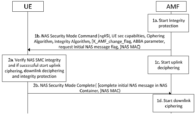
Below is an explanation of the steps involved:
-
AMF Initiates Security: -
1a. Start Integrity Protection: The AMF begins integrity protection for NAS signaling using the derived key K_NASint (from the 5G key hierarchy). This ensures that NAS messages cannot be tampered with.
-
1b. NAS Security Mode Command: The AMF sends a NAS Security Mode Command to the UE, specifying the selected security algorithms (e.g., ngKSI for key set identifier, UE security capabilities, ciphering algorithm, integrity algorithm), an indicator for K_AMF change (if applicable), the Anti-Bidding down Between Architectures (ABBA) parameter, a request for an initial NAS message (if needed), and a NAS Message Authentication Code (NAS MAC). The NAS MAC is generated using K_NASint to allow the UE to verify the message’s integrity.
-
1c. Start Uplink Deciphering: The AMF starts deciphering uplink NAS messages from the UE using K_NASenc, preparing to process encrypted messages from the UE.
-
UE Processes the Command: -
2a. Verify NAS SMC Integrity: The UE verifies the integrity of the NAS Security Mode Command by checking the NAS MAC using its own K_NASint. If successful, the UE starts uplink ciphering (using K_NASenc) and downlink deciphering (using K_NASenc) to encrypt and decrypt NAS messages, as well as integrity protection (using K_NASint) for both directions.
-
2b. NAS Security Mode Complete: The UE responds with a NAS Security Mode Complete message, which includes the complete initial NAS message (if requested) in a NAS container and a NAS MAC for integrity protection. This confirms the successful setup of NAS security.
-
AMF Finalizes Security: -
1d. Start Downlink Ciphering: Upon receiving the NAS Security Mode Complete message, the AMF verifies the NAS MAC using K_NASint. If successful, the AMF starts ciphering downlink NAS messages to the UE using K_NASenc, completing the security setup for bidirectional NAS communication.
User Plane Security
User Plane Security in 5G is a critical mechanism that ensures the confidentiality, integrity, and protection of user data transmitted between the User Equipment (UE) and the network. It is established after successful authentication and security mode procedures, where the gNB and UE derive encryption and integrity protection keys from the key hierarchy. Encryption is applied to safeguard user data against eavesdropping, while integrity protection ensures that transmitted packets remain unaltered and authentic. The security configuration, including the selected encryption and integrity algorithms, is determined during the Access Stratum (AS) Security Mode Command procedure. By implementing strong cryptographic protections, user plane security in 5G enhances privacy, prevents unauthorized access, and ensures the reliability of data transmission across the network.
Follwoing diagram illustrates the User Plane (UP) security activation mechanism in 5G networks, detailing the process to enable integrity and ciphering protection for user data between the User Equipment (UE) and the gNB/ng-eNB (5G base station). The procedure builds on the already established RRC (Radio Resource Control) security to activate UP security for each Data Radio Bearer (DRB).
< 33.501 - Figure 6.6.2-1: User plane (UP) security activation mechanism >
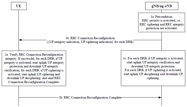
Below is an explanation of the steps involved:
-
gNB/ng-eNB Initiates UP Security: -
1a. Precondition: The gNB/ng-eNB ensures that RRC security is already activated, meaning RRC ciphering (using K_RRCenc) and RRC integrity protection (using K_RRCint) are in place, as established during the AS Security Mode Command procedure.
-
1b. RRC Connection Reconfiguration: The gNB/ng-eNB sends an RRC Connection Reconfiguration message to the UE, specifying the UP security settings for each DRB. This includes the UP integrity indication (whether integrity protection is enabled) and the UP ciphering indication (whether encryption is enabled) for each DRB.
-
1c. Activate UP Security: For each DRB, the gNB/ng-eNB activates UP security based on the configured settings. If UP integrity is activated, the gNB/ng-eNB starts downlink UP integrity verification and protection using K_UPint. If UP ciphering is activated, it starts uplink UP deciphering and downlink UP ciphering using K_UPenc.
-
UE Processes the Reconfiguration: -
2a. Verify RRC Connection Reconfiguration: The UE verifies the integrity of the RRC Connection Reconfiguration message using K_RRCint. If successful, the UE applies the UP security settings for each DRB. If UP integrity is activated, the UE starts uplink UP integrity protection and downlink UP integrity verification using K_UPint. If UP ciphering is activated, the UE starts uplink UP ciphering and downlink UP deciphering using K_UPenc.
-
2b. RRC Connection Reconfiguration Complete: The UE sends an RRC Connection Reconfiguration Complete message to the gNB/ng-eNB, confirming the successful activation of UP security for the specified DRBs. This message is integrity-protected using K_RRCint.
Key Handling in Handover
Key handling in handover in 5G is a crucial security process that ensures the continuity and protection of encrypted communications as the UE moves between different gNBs. During handover, the security context, including encryption and integrity keys, must be securely transferred while preventing key reuse and exposure. The key derivation follows a hierarchical structure, where a new key, KgNB, is generated for the target gNB based on the previously established security anchor key. This ensures forward and backward security, preventing attackers from deriving past or future keys even if a session key is compromised. The handover key management process also incorporates the Next Hop (NH) mechanism, which strengthens security by generating fresh keys for each handover event. By maintaining a robust key handling framework, 5G ensures seamless, secure transitions between cells, reducing the risk of interception and ensuring uninterrupted, protected communication.
Following diagram illustrates the model for key handling during handovers in 5G networks, focusing on the key chaining process to maintain security as the User Equipment (UE) transitions between gNBs (5G base stations). The process ensures continuity of secure communication by deriving and distributing new keys while managing the NAS (Non-Access Stratum) uplink COUNT and Next Hop (NH) parameters.
< 33.501 - Figure 6.9.2.1.1-1: Model for the handover key chaining >
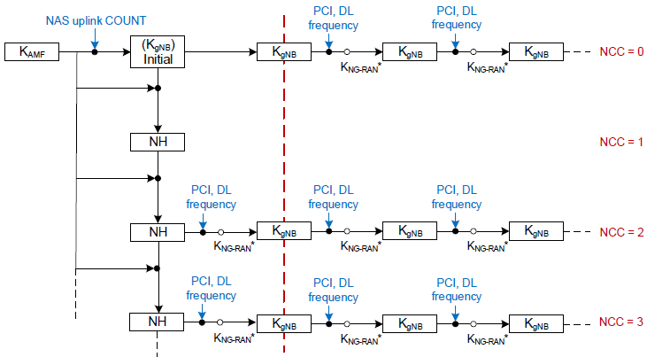
Below is an explanation of the key handling and chaining process:
-
Initial Key Setup: -
The process begins with the K_AMF key, which is the anchor key at the AMF (Access and Mobility Management Function). From K_AMF, an initial K_gNB (denoted as K_gNB Initial) is derived, along with the initial NAS uplink COUNT. This K_gNB is used to secure communication between the UE and the initial gNB.
-
Key Chaining and NH Derivation: -
During a handover, the network uses the Next Hop Chaining Counter (NCC) to track the key derivation chain. The NCC starts at 0 for the initial K_gNB.
-
First Handover (NCC = 0 to NCC = 1): The AMF or the current gNB derives a Next Hop (NH) key from K_AMF (or the current K_gNB) using the NAS uplink COUNT. This NH, along with parameters like PCI (Physical Cell Identity), DL (Downlink) frequency, and K_gNB-RAN (a key derived for the target gNB), is used to derive a new K_gNB for the target gNB. The NCC is incremented to 1, and this new K_gNB is used for communication with the new gNB.
-
Subsequent Handovers (NCC = 1 to NCC = 2, NCC = 3, etc.): For each subsequent handover, the process repeats. A new NH is derived from the previous NH (or K_gNB) using PCI, DL frequency, and K_gNB-RAN. The NCC is incremented (e.g., to 2, then 3), and a new K_gNB is derived for each target gNB. This creates a chain of K_gNB keys, each tied to a specific NCC value.
-
Key Derivation and Distribution: -
The K_gNB-RAN keys are intermediate keys derived during the handover process, ensuring that each gNB has a unique K_gNB. The PCI and DL frequency parameters ensure that the derived keys are specific to the target cell, preventing key reuse across cells.
-
The NH key acts as a bridge between handovers, allowing the network to derive fresh K_gNB keys without needing to re-authenticate the UE with the AMF, thus reducing signaling overhead.
Reference :
- 3GPP 33.501 - 5G; Security architecture and procedures for 5G System
- 5G SECURITY ISSUES - GSMA
- 4G vs 5G Security, The Key Differences - CableLabs - 2019
- Why 5G Can Be More Secure Than 4G - 2019
- How 5G is both less and more secure than previous networks - 2020
- 5G Security Risks You Need to Know About - 2023
- The risks of 5G security - 2023