I think the technical logics of NR sidelink is almost same as LTE sidelink. That is to develop a full stack protocol that enable direct communication between UEs without getting any cellular network involved. In LTE, it was designed to use UL waveform in both direction (i.e, Tx and Rx) meaning that we need to develop additional stacks on UE side to receive and process 'UL-like waveform (SC-FDMA)'. In case of NR, the scope of new development would not be as much as LTE since fundamentals of UL wave and DL waveform is same (i.e, OFDMA). But some degree of PHY modification would still be required.
- Physical Channels and Signals in Sidelink
- Sidelink Synchronization
- Mode 1 and Mode 2 : Who Chooses the Resources
- Unicast, Groupcast and Broadcast
- The Two Stage SCI
- The Protocol Stack over PC5
- Reference
Physical Channels and Signals in Sidelink
Completely new set of physical channels are specified as shown below. One thing to notice is that both UE in Sidelink transmit SSB and both UE schedules its own physical layer data. It implies that UE has basic component of gNB capability.
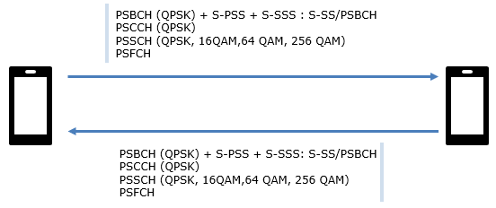
The same list appears twice : the channel list is repeated above the forward arrow and below the return arrow. Both UEs transmit the whole set, which is the point the paragraph above is making.PSBCH (QPSK) + S-PSS + S-SSS : S-SS/PSBCH : the first line groups three things and then names the group. 38.211 calls that group the S-SS/PSBCH block, and it is the sidelink counterpart of the SSB.PSCCH (QPSK) : the control channel carries the first stage SCI. QPSK is the only modulation it ever uses.PSSCH (QPSK, 16QAM, 64 QAM, 256 QAM) : the shared channel carries the data. Those four schemes are Table 8.3.1.2-1 of 38.211, and they match the downlink set.PSFCH has no modulation written beside it : that is correct rather than an omission. PSFCH format 0 is a sequence, so there is no modulation order to record.
Four physical channels, and nothing else. Clause 8.1.1 of 38.211 defines PSSCH, PSBCH, PSCCH and PSFCH, and that list has not grown since Release 16. The useful comparison is with the Uu channel each one replaces.
Sidelink channel |
Closest Uu channel |
What it carries |
Modulation |
PBCH |
MasterInformationBlockSidelink, carried inside the S-SS/PSBCH block. |
QPSK |
|
PDCCH |
The first stage SCI, which is SCI format 1-A or 1-B. |
QPSK |
|
PDSCH and PUSCH together |
SL-SCH data, with the second stage SCI multiplexed into it. |
QPSK, 16QAM, 64QAM, 256QAM |
|
PUCCH |
HARQ feedback for a received PSSCH. |
Format 0 sequence, so no modulated data |
One row of that table does two jobs. PSSCH replaces PDSCH and PUSCH at once, because a sidelink UE both sends and receives on it. That is the physical layer expression of the point made above, that a sidelink UE holds part of what a gNB does.
The physical signals are listed separately in clause 8.1.2, and that list has grown. DM-RS, CSI-RS, PT-RS, S-PSS and S-SSS were present from the start. Release 18 added the sidelink positioning reference signal,
Four channels cover everything : PSSCH, PSBCH, PSCCH and PSFCH, and no sidelink transmission uses anything outside that set.PSSCH is two Uu channels in one : it carries data in both directions, so it covers both PDSCH and PUSCH.PSFCH is a sequence rather than a modulated channel : only format 0 is defined for it, which is why the drawing shows no modulation beside it.The signal list is the part that keeps changing : SL PRS arrived with sidelink positioning, and it is the only physical signal added since the original set.
Numerology on Sidelink
A numerology table is worth reading for what it leaves out as much as for what it lists. The one below stops one row earlier than most readers expect, and where it stops decides which bands sidelink can use.
The numerologies supported by Sidelink is same as in regular NR numerology as shown below.

The heading names the source : this is Table 8.2.2-1 of 38.211, so it is the sidelink table rather than the general one.The middle column is a formula, not a list : Δf = 2μ · 15 kHz gives 15, 30, 60 and 120 kHz for μ from 0 to 3.Only the 60 kHz row offers a choice : it reads Normal, Extended, while every other row reads Normal alone.The table ends at μ = 3 : there is no 240 kHz row, and nothing above it either.
Sidelink uses four subcarrier spacings : 15, 30, 60 and 120 kHz, chosen for a sidelink BWP by the higher layer parameter sl-BWP.Extended cyclic prefix exists at 60 kHz only : the same restriction the Uu table applies, carried over unchanged.
Sidelink Synchronization
Two UEs outside coverage have no cell to synchronise to, and no clock they already share. Something has to do the job the SSB does on Uu. That something is the S-SS/PSBCH block, and it resembles an SSB closely while differing in ways worth reading carefully.
The block carries the same three components as an SSB. S-PSS occupies symbols 1 and 2, S-SSS occupies symbols 3 and 4, and PSBCH takes symbol 0 and every symbol from 5 upward. In frequency it occupies 132 contiguous subcarriers, which is 11 resource blocks.
The dimensions are where the two differ. A Uu SSB is 4 symbols long and 240 subcarriers deep. An S-SS/PSBCH block is 13 symbols long under normal cyclic prefix, and 11 under extended, while being narrower at 132 subcarriers. It is a tall thin block rather than a short wide one.
That shape follows from what it has to do. A UE transmits with far less power than a gNB, so the block is spread over more symbols to gather more energy. It also has to fit inside a sidelink BWP that may be narrow, so it cannot afford 20 resource blocks of width.
The identity space differs too, and this is the more useful difference. 38.211 defines 672 physical layer sidelink synchronization identities, against 1008 cell identities on Uu. Those 672 split into two named halves. Identities 0 to 335 form the set
The split carries meaning rather than being a numbering convenience. A transmitter that is itself synchronised to a network uses an identity from id_net. A transmitter running on its own clock uses one from id_oon. A receiving UE therefore learns the quality of the timing source before decoding anything that source sent.
Timing has one fixed quantity. The period is always 16 frames, which is 160 ms, and only the contents of the period are configurable. Within it
The PSBCH payload is small, and part of it is a slot format. A UE puts a 12 bit sequence, a0 to a11, in the payload to convey
The S-SS/PSBCH block replaces the SSB : the same three components, so the acquisition procedure a reader already knows still applies.Tall and thin rather than short and wide : 13 symbols by 11 resource blocks, against 4 symbols by 20 for a Uu SSB.672 identities, split in half by meaning : id_net for a transmitter synchronised to a network, id_oon for one that is not.The period never changes : 16 frames, so 160 ms, with only the count and the spacing inside it configurable.
Mode 1 and Mode 2 : Who Chooses the Resources
Every sidelink transmission needs a time and frequency resource, and something has to choose it. On Uu that question never arises, because the gNB schedules everything. Sidelink has to answer it twice, once for a UE inside coverage and once for a UE outside it.
Clause 16.9.3 of 38.300 names the two answers. Scheduled resource allocation puts the gNB in charge, and UE autonomous resource selection puts the UE in charge. Most writing calls them mode 1 and mode 2, while the specification text uses the longer names.
Mode 1 has one hard precondition. The UE has to be in RRC_CONNECTED before it can transmit, because the grant arrives on PDCCH. The gNB sends DCI format 3_0 with the CRC scrambled by
Two configured grant types exist beside the dynamic one. Type 1 is supplied entirely by RRC, so no PDCCH is needed to start it. Type 2 has RRC supply the periodicity while PDCCH supplies the activation, addressed to
To schedule anything the gNB needs to know what is queued. The UE reports that with a sidelink buffer status report, and the report is organised per destination rather than per bearer. Eight logical channel groups are used for it, and two formats exist, SL BSR and truncated SL BSR.
Mode 2 removes the gNB from the decision. The UE selects its own resources from a resource pool, and the pool reaches it in one of three ways. SIB12 carries it inside coverage, dedicated signalling can carry it as well, and a pre-configuration carries it outside coverage.
One property of mode 2 pools deserves separate attention. A pool can be given a validity area, so a UE moving inside that area does not have to acquire a new one. There is also an exceptional transmission resource pool, used with random selection, which covers the moments when the normal procedure cannot run. A UE uses it during handover.
|
Mode 1 : scheduled |
Mode 2 : autonomous |
The gNB. |
The UE itself. |
|
RRC_CONNECTED only. |
Any state, and outside coverage as well. |
|
DCI format 3_0 on PDCCH, or a configured sidelink grant of Type 1 or Type 2. |
Selected by the UE from a resource pool. |
|
SL-RNTI for a dynamic grant, SL-CS-RNTI for configured grant Type 2. |
None. No PDCCH is read. |
|
RRCReconfiguration on Uu. |
SIB12, dedicated signalling, or a pre-configuration. |
|
Sidelink BSR, per destination. |
Nothing to the network. |
Coverage decides the mode : mode 1 needs a serving cell and RRC_CONNECTED, and mode 2 needs neither of them.Mode 1 reuses the Uu scheduling machinery : a DCI on PDCCH, an RNTI, dynamic and configured grants, and a buffer status report.The sidelink BSR is grouped by destination : eight logical channel groups per destination, which is not how a Uu BSR is organised.Mode 2 depends entirely on pool configuration : the pool comes from SIB12, from dedicated signalling, or from a pre-configuration the UE already holds.
Unicast, Groupcast and Broadcast
A sidelink transmission does not always have one intended receiver. It may serve one peer, a group of peers, or everyone listening, and the three cases need different amounts of machinery. 38.300 defines each of them for one pair of Source and Destination Layer-2 IDs.
Unicast is the fully equipped case. One PC5-RRC connection exists between the two UEs. HARQ feedback is available, sidelink transmit power control is available, RLC AM can be used, and radio link failure can be detected on the connection.
Groupcast retains the feedback and little else. UEs belonging to the group receive the traffic, and HARQ feedback is supported. RLC runs in UM only, and the transmission is unidirectional.
Broadcast retains almost none of that machinery. Traffic reaches every UE that is listening, and no feedback exists at all. RLC is UM and unidirectional here as well.
The cast type is not implied by the identifiers. It is signalled explicitly, in a two bit Cast type indicator field of SCI format 2-A. Its four values do not map one to one onto the three cast types.
Groupcast takes two of the four values, and the feedback rule is what separates them. Value 01 is groupcast where the HARQ feedback includes ACK or NACK. Value 11 is groupcast where the feedback includes NACK only. Value 00 is broadcast and value 10 is unicast.
NACK only feedback exists for a practical reason. A group can be large, and an ACK from every member would cost more resources than the transmission itself. A receiver that stays silent is treated as having received the packet.
Three cast types, four code points : groupcast occupies two of them, because it has two different feedback rules.Only unicast has a PC5-RRC connection : power control, RLC AM and link failure detection all follow from that connection existing.NACK only feedback trades certainty for capacity : silence counts as success, which keeps the PSFCH cost independent of the group size.
The Two Stage SCI
A UE listening on a resource pool has to decode control information before it knows whether a transmission concerns it at all. Reading a long control message for every transmission in the pool would be expensive. NR splits the control information in two, and that split is the most distinctive thing about sidelink control.
The first stage travels on PSCCH, and clause 8.3 of 38.212 defines it. SCI format 1-A is used for scheduling PSSCH. SCI format 1-B arrived later, and it schedules a sidelink positioning reference signal in a dedicated pool.
What the first stage states is where the transmission sits. It carries Priority, a Frequency resource assignment, a Time resource assignment, a Resource reservation period, a DMRS pattern, a Modulation and coding scheme, and a two bit field naming the second stage format.
The second stage travels on PSSCH, multiplexed with the data it describes. Four formats exist, which are 2-A, 2-B, 2-C and 2-D. What they state is who the transmission is for, and how it should be acknowledged.
SCI format 2-A is the general one. It carries a HARQ process number, a New data indicator and a Redundancy version. It then carries a Source ID of 8 bits and a Destination ID of 16 bits. Three smaller fields close it : a HARQ feedback enabled or disabled indicator, the Cast type indicator, and a CSI request.
The other three are specialisations. Format 2-B replaces the cast type and CSI fields with a Zone ID and a Communication range requirement, which is how distance based groupcast works. Format 2-C carries inter-UE coordination information, and it is defined for unicast only. Format 2-D schedules a sidelink positioning reference signal, and it embeds format 2-A or 2-B inside itself.
The division of labour explains why sensing is possible. Every UE in the pool decodes every first stage SCI, because the Resource reservation period announces resources the transmitter intends to use again. A UE choosing its own resources under mode 2 reads those announcements and avoids what has already been claimed.
Only after that does a UE need the second stage. The Destination ID tells it whether the packet is its own. By then it has already taken from the first stage everything its own resource selection required.
The first stage says where, the second says who : location and reservation on PSCCH, identity and HARQ on PSSCH.Every UE reads every first stage SCI : that is not wasted work, because the reservation field is what mode 2 sensing depends on.The second stage travels on PSSCH : it is multiplexed with the data, so it costs no separate control resource.Four second stage formats, one general case : 2-A covers ordinary traffic, while 2-B, 2-C and 2-D serve distance based groupcast, inter-UE coordination and positioning.
The Protocol Stack over PC5
The physical layer is the part that had to be invented. Above it the sidelink stack reuses the Uu sublayers almost unchanged, and the interesting content is in the restrictions rather than in the structure. The interface the whole stack runs over is called PC5.
Four stacks are defined rather than one, because sidelink carries four kinds of traffic. User plane traffic uses SDAP, PDCP, RLC and MAC over the physical layer. PC5-RRC signalling uses RRC, PDCP, RLC and MAC. PC5-S signalling puts PC5-S above PDCP in place of RRC. Broadcast signalling uses RRC, RLC and MAC with no PDCP at all.
Three logical channels carry that traffic.
The mapping down to transport channels is short. SCCH and STCH both map to SL-SCH. SBCCH maps to SL-BCH. Nothing corresponds to PCH or to RACH, because no cell exists to page a UE or to admit one.
Radio bearers split the same way as on Uu. Sidelink data radio bearers carry the user plane, and sidelink signalling radio bearers carry the control plane. Separate SL SRBs on different SCCHs are used for PC5-RRC and for PC5-S.
The restrictions are where sidelink differs from Uu. Reflective QoS is not supported over PC5. Out of order delivery in PDCP is available for unicast only. RLC AM is available for unicast only, and TM is used for SBCCH.
PC5-RRC is a peer to peer protocol rather than a network to UE one. A PC5-RRC connection corresponds one to one with a PC5 unicast link, and a UE can hold several at once with different peers. Both UEs exchange capabilities and configuration through separate procedures in each direction, because neither of them is in charge.
The message names follow a consistent pattern, and 38.331 defines all of them.
MasterInformationBlockSidelink : the sidelink system information a UE transmits on SL-BCH, over SBCCH in TM.RRCReconfigurationSidelink : the command that configures the AS of a PC5-RRC connection. It applies to unicast only.UECapabilityEnquirySidelink andUECapabilityInformationSidelink : the capability exchange between two peers, again for unicast only.MeasurementReportSidelink : sidelink measurement results, reported from one UE to the other.NotificationMessageSidelink : sent by a relay UE to the remote UE it serves, in either the U2N or the U2U case.SidelinkUEInformationNR : the exception. It travels on Uu over SRB1, and it is how a UE tells the network what sidelink resources it wants.
The stack is the Uu stack with restrictions : the same five sublayers, with fewer options available inside each of them.Four control plane arrangements, not one : PC5-RRC, PC5-S and SBCCH each stack differently above MAC.PC5-RRC is symmetric : each peer configures the other with its own procedure, because there is no master among them.SidelinkUEInformationNR runs on Uu rather than PC5 : it is how a mode 1 UE asks for resources, and how it reports QoS per destination.
Reference :
[1] The 5G Evolution:3GPP Releases 16-17 (5G Americas)
[2] 38.211 v19.4.0 : NR - Physical channels and modulation. Clause 8 was read for the sidelink channels, the numerology table, the synchronization identities and the S-SS/PSBCH block structure.
[3] 38.212 v19.4.0 : NR - Multiplexing and channel coding. Clauses 8.3 and 8.4 were read for the first and second stage SCI formats.
[4] 38.213 v19.4.0 : NR - Physical layer procedures for control. Clause 16.1 was read for the S-SS/PSBCH block timing.
[5] 38.300 v19.3.0 : NR and NG-RAN Overall description. Clause 16.9 was read for the cast types, the protocol stack and the two resource allocation modes.
[6] 38.331 v19.3.0 : NR - Radio Resource Control (RRC) protocol specification. The sidelink message descriptions in clause 6.3 were read.