The 6G air interface (6GR) study consolidates contributions from a wide range of companies to define the high-level design principles, targets, and overall architecture for 6G. The work emphasizes creating a single RAT capable of supporting diverse device types, service categories, and spectrum environments. Key design aspects include scalable channel bandwidth definitions (minimum and maximum), flexible coverage strategies, robust initial access and common channel design, and mechanisms for multiplexing and collision management such as MRSS (Multi-RAT Spectrum Sharing). Proposals also highlight service and spectrum efficiency, support for both existing and emerging services, and harmonized operation across all duplex types. A central goal is to ensure seamless integration of terrestrial networks (TN) and non-terrestrial networks (NTN), while exploring compatibility with 5G NR to enable efficient 5G–6G coexistence.
Some of important highlights on this topics includes
- System Architecture & Design Principles
- Migration & Deployment Strategies
- Spectrum & Duplexing
- Waveform, Numerology, Modulation & Coding
- Synchronization & Initial Access
- Control Channels & Scheduling
- MIMO, Beamforming & Reference Signals
- Channel State Information (CSI) & Feedback
- HARQ & Retransmission Efficiency
- Mobility, Resilience & Security
- Coverage Enhancements
- Power Efficiency
- Channel and Antenna Modeling
- Network Controlled Repeaters (NCR) & Reconfigurable Intelligent Surfaces (RIS)
- AI/ML Integration
- New Service Types & Verticals (IoT, XR, FWA, etc.)
- Integrated Sensing & Communication (ISAC/ISPC)
- NTN (Non-Terrestrial Networks) Integration
- Device Types & Capability Frameworks
- Testing, Certification & Standardization Processes
System Architecture & Design Principles
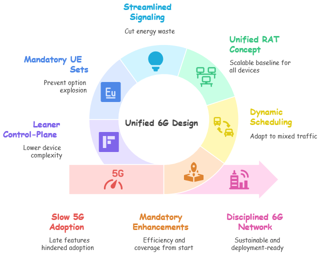
The foundation of 6G is not just about new technologies. It is about building a radio interface that lasts, scales, and adapts to future needs. Earlier generations often traded performance for more complexity. 6G focuses on universality, sustainability, and practicality.
The air interface must be open, secure, energy-efficient, and forward-compatible. It should grow through clear milestones, not fragmented releases. A key idea is “keep–change–add.” Keep what works in NR. Change only the parts that block progress. Add carefully chosen new features like ISAC, AI-native functions, NTN, and advanced IoT.
The design stays grounded in real deployment needs. 6G targets early-stage problems like coverage, efficiency, and complexity. It also avoids over-engineering for rare use cases.
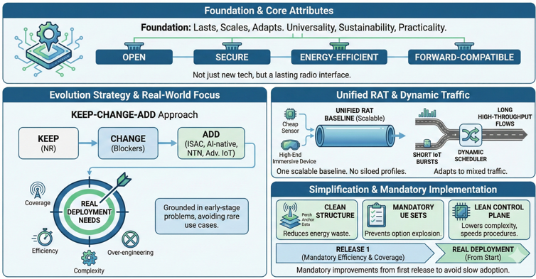
A key change is to make efficiency and coverage improvements mandatory from the first release. This avoids the slow adoption seen with late 5G features. The focus is on real deployment from the start.
This also applies to traffic behavior. 6G must handle both short IoT bursts and long high-throughput flows. The scheduler must adapt dynamically to mixed traffic.
To reduce fragmentation, 6G aims for a unified RAT. One scalable baseline should support everything from cheap sensors to high-end immersive devices. This avoids siloed profiles that make networks complicated.
Simplification is a core goal. A clean perch/anchor/data structure reduces energy waste from always-on signals. Mandatory UE capability sets prevent option explosion. A lean control plane lowers device complexity and speeds up procedures.
Together, these guiding principles sketch a vision of 6G as not only faster or more capable than its predecessors, but also more disciplined, sustainable, and deployment-ready from the very beginning.
Universal design goals : open, secure, flexible, energy-efficient, forward compatible.- Prioritize longevity and smooth evolution across releases.
- Balance performance with deployment practicality.
Keep–change–add principle : keep proven NR elements, change where gains exist, add ISAC/AI/IoT/NTN.- Reduce risk by reusing validated components.
- Focus changes on high-impact bottlenecks (e.g., control, MIMO).
Design for real deployments : solve “Day-1” problems; avoid niche over-engineering.- Make efficiency features mandatory in the first release.
- Limit optionality to curb fragmentation.
Traffic-behavior–driven design : efficient for bursty small sessions and large flows.- Fast setup for short transactions; efficient ramp-up for big flows.
- Scheduling aware of mixed traffic patterns.
Unified RAT concept : one 6GR for diverse devices/services with a scalable framework.- Common baseline spanning IoT to high-end UEs.
- Minimize parallel “profiles” to simplify networks.
Perch/Anchor/Data framework : reduced raster “Perch”, minimized “Anchor”, lean “Data”.- Cut always-on signaling for network energy savings.
- Separate discovery/control from high-throughput data.
UE capability framework : mandatory capability sets; minimize optional combinations.- Define device-type/use-case tiers to avoid “option explosion”.
- Simplify interoperability and certification.
Other simplifications : PxSCH interleaving, simpler BWP adaptation, flattened RRC.- Lower UE complexity and blind-decode burden.
- Speed up control-plane procedures.
Migration & Deployment Strategies
Migration and deployment in 6G must avoid the messy 4G to 5G path. Too many migration options and late SA adoption slowed 5G and increased the burden on networks and devices.
6G takes a disciplined, needs-based approach. It aims to reuse existing infrastructure while delivering real performance gains from the start.
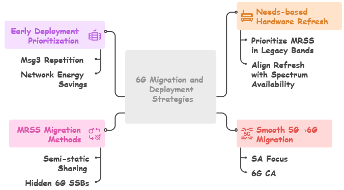
Operators should reuse radios as much as possible. Hardware refresh should happen only when spectrum or business needs require it. No forced forklift upgrades.
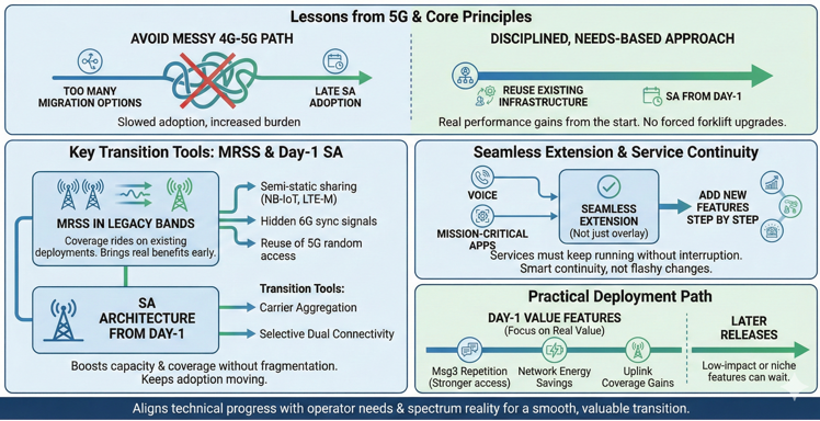
A core part of this vision is MRSS in legacy bands. This lets 6G coverage ride on existing deployments. It brings real benefits early, even before new spectrum becomes common.
6G starts with standalone architecture from Day-1. MRSS, carrier aggregation, and selective dual connectivity act as transition tools.
This approach boosts capacity and coverage without fragmenting the ecosystem. It also keeps adoption moving forward.
The migration goal is to make 6G a seamless extension, not just another overlay. Services like voice and mission-critical apps must keep running without interruption. Operators can add new features step by step.
MRSS plays a key role. Examples include semi-static sharing with NB-IoT and LTE-M, hidden 6G sync signals, and reuse of 5G random access. These make 6G invisible to existing NR devices and prevent cross-generation interference.
Deployment follows a practical path. Focus goes to features with real value from Day-1. Examples are Msg3 repetition for stronger access, network energy savings, and uplink coverage gains. Low-impact or niche features can wait for later releases.
6G migration is about smart continuity, not big flashy changes. It aligns technical progress with operator needs and spectrum reality to make the transition smooth and valuable from the start.
Needs-based hardware refresh — reuse existing radios; selective upgrades.- Prioritize MRSS in legacy bands for early coverage.
- Align refresh with spectrum availability/business case.
Smooth 5G→6G migration — SA focus, MRSS in existing bands, 6G CA, optional DC/DS.- Leverage CA to add capacity without forklift upgrades.
- Maintain service continuity for voice/mission-critical.
MRSS migration methods — semi-static sharing incl. NB-IoT/LTE-M; hidden 6G SSBs; reuse 5G RA.- Rate-matching and signal sharing to avoid collisions.
- Backward “invisibility” to NR UEs.
Early deployment prioritization — prioritize features with early commercial value.- Examples: Msg3 repetition, NES, coverage essentials.
- Defer low-impact features to later releases
More on MRSS
A core pillar of 6G migration is MRSS from Day-1. It enables coexistence and smooth evolution. 6G and 5G NR can run on the same spectrum, using the same radios, without disrupting current services.
MRSS is more efficient than 5G’s DSS. DSS had heavy overhead from LTE reference signals. MRSS builds on a clean NR baseline with no CRS, flexible CORESETs, and lower control overhead.
MRSS acts as a natural bridge for migration. It removes the need for full spectrum re-farming. 6G waveforms and frame structures stay CP-OFDM compatible. Subcarrier spacing and numerology stay aligned with NR. Both systems can share the same grid without conflict.
In practice, MRSS brings early 6G gains without breaking NR continuity. Improving spectral efficiency and cell-edge performance may be more important than chasing peak rates.
With carrier aggregation, operators can combine NR and 6G carriers for higher throughput. MRSS stays invisible to legacy UEs. Rate-matching and flexible resource use let 6G fill gaps in NR scheduling, avoiding collisions and improving utilization.
In areas where tight inter-RAT coordination is hard, MRSS can work with dual connectivity or dual-stack. But MRSS stays the main baseline.
MRSS is more than just a migration tool. It also aligns numerology. By keeping the same SCS and FFT sizing between NR and 6G, handover becomes simpler. Device complexity goes down. Spectrum planning stays clean and unified. 6G looks like a natural NR extension in both signaling and traffic.
MRSS corrects the problems of 5G DSS. DSS was a quick patch between LTE and NR, but it was not so efficient and practical. However MRSS is built to be efficient, forward-compatible, and commercially practical. It lets 6G use existing spectrum and radios right away, while preparing for new mid-band spectrum later.
-
Core Concept - Coexistence of 5G NR and 6G on the same spectrum resources.
- Uses existing 5G radio units (no immediate forklift upgrades).
- Designed to be backward invisible to NR UEs (they don’t “see” 6G signals).
-
Lessons from 5G DSS vs. MRSS - DSS problem: LTE’s legacy CRS and rigid overhead reduced efficiency.
- MRSS advantage: Built on NR’s lean design (no CRS, flexible CORESETs).
- Expected to be more resource-efficient than DSS ever was.
-
Waveform and Numerology Alignment - MRSS requires CP-OFDM compatibility between 5G and 6G.
- Reuses 5G scalable subcarrier spacing and frame structure.
- Ensures multiplexing of 5G/6G signals on the same grid without hardware divergence.
- Numerology harmonization (same SCS/FFT sizes) simplifies mobility and reduces UE complexity.
-
Resource Utilization & Rate Matching - Flexible resource allocation and rate-matching so 6G can fill unused NR resources.
- Prevents collisions with NR traffic while maximizing utilization.
- Semi-static sharing across NB-IoT and LTE-M also considered.
- Hidden 6G SSBs and reuse of NR RA procedures for seamless operation.
-
Deployment Options - MRSS + 6G Carrier Aggregation (CA) to combine 6G carriers with MRSS bands.
- Fallback when tight inter-RAT coordination is difficult: 6G–5G Dual Connectivity (DC) or Dual Stack (DS).
- Enables staged migration without disrupting NR services.
-
Operator and Ecosystem Benefits - Early 6G coverage in existing 5G bands before new spectrum is widely available.
- Reuses existing radios, lowering deployment costs.
- Provides continuity for mission-critical services (voice, emergency, industrial IoT).
- Simplifies handover and mobility across generations through shared numerology.
- Avoids fragmentation by aligning 6G evolution with real operator needs.
Spectrum & Duplexing
Spectrum and duplexing in 6G are both a challenge and an opportunity. The aim is to simplify what became fragmented in 5G.
Channel sizes will grow. The target is 200 MHz in FR1 and FR3, and 400 MHz in FR2-1. At the same time, 6G will still support very narrow bands, down to 3 MHz, for low-end IoT.
This dual goal needs flexible numerology. 8k FFT and 60 kHz SCS in FR1/FR3 help balance efficiency and implementation cost.
Spectrum use will become more integrated. Native multi-carrier support with cross-carrier scheduling, HARQ, and CORESET control lets carriers act as one logical block. This gives operators more freedom to place uplink and downlink across different bands.
Efficiency is a core part of the 6G vision. Studies focus on site densification, TRP coordination, and larger antenna arrays near 7 GHz. The goal is to find where real performance gains justify the cost of power and infrastructure, especially when UE antenna scaling hits practical limits.
On the duplexing side, simplicity and robustness come first. FDD and semi-static TDD stay as the main options. SBFD (Sub-Band non-overlapping Full-Duplex) is being studied to boost uplink coverage and reduce latency. Dynamic TDD is avoided due to interference and deployment complexity.
Carrier aggregation is the common method for combining spectrum. Fast activation and deactivation of CCs make aggregation agile and low-latency. It works smoothly across bands, supporting both high-throughput bursts and low-power idle modes.
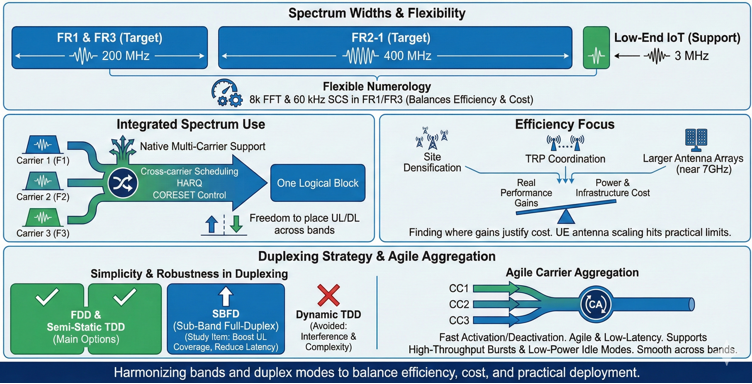
The main idea is simple: 6G spectrum and duplexing are not just about wider channels. They aim to harmonize bands and duplex modes to balance efficiency, cost, and practical deployment.
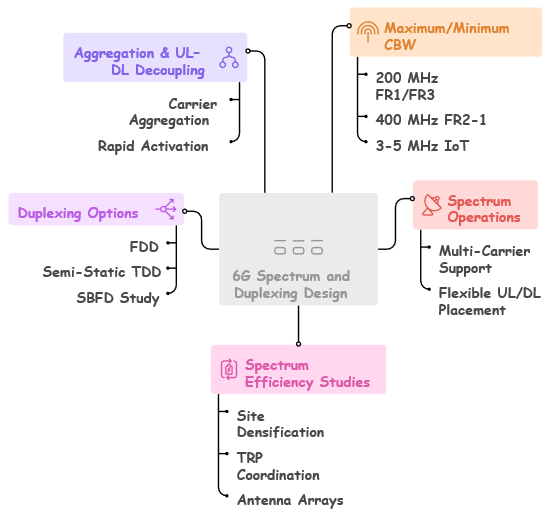
Maximum / Minimum Carrier Bandwidth (CBW) - 6G FR1/FR3 targets up to 200 MHz per component carrier.
- 6G FR2-1 targets up to 400 MHz per component carrier.
- Device-side CC bandwidth expected to scale up to 400 MHz for new 6–8+ GHz bands.
- Large bandwidth is needed to compensate for higher pathloss and support higher peak rates.
- Narrow 5 MHz baseline remains supported for broad spectrum reuse.
- 3 MHz minimum channel bandwidth is optionally supported for low-power IoT devices.
- Sync raster design and initial access flow must remain functional even at 3–5 MHz operation.
- 6G aims to retain compatibility with narrow legacy allocations used by IoT ecosystems.
- 8k FFT or 60 kHz SCS are considered as alternatives for FR1/FR3 large-bandwidth operation.
Spectrum Operations & Multi-Carrier Behavior - 6G assumes native multi-carrier operation across wide spectrum ranges.
- Supports flexible DL/UL decoupling across bands to optimize both coverage and capacity.
- Cross-carrier scheduling, cross-carrier HARQ, and shared CORESETs are baseline behaviors.
- Carriers can be grouped so control is sent on one carrier while data follows on others.
- Giga-MIMO in FR3 (6–8+ GHz) with up to 1000-element arrays enhances multi-carrier efficiency.
- 6G spectrum operations integrate smoothly with MRSS for reuse of 5G bands.
- Supports coordinated TRP selection and densification for high-capacity clusters.
- Flexible UL/DL placement across carriers allows partial decoupling for uplink-heavy services.
Spectrum Efficiency Studies & Deployment Factors - Study efficiency trade-offs across 2–5 GHz, 6–8+ GHz, and FR2-1 regions.
- Consider 7 GHz offset scenarios where additional antennas compensate pathloss.
- Quantify capacity gain vs. additional site cost and power consumption.
- UE antenna scaling is limited — smartphone 4Tx/8Rx is the practical baseline.
- Site densification must be balanced with spectrum reuse and power efficiency.
- Ensure uplink coverage does not degrade when shifting to higher mid-bands.
- Spectrum strategy must include coexistence with 5G and migration from existing bands.
Duplexing Options (FDD, TDD, SBFD) - 6G supports both FDD and semi-static TDD in legacy and lower mid-band spectrum.
- Dynamic TDD is de-prioritized due to cross-link interference and complexity.
- SBFD (Split-Band Full Duplex) becomes the preferred solution for high mid-bands.
- SBFD enables uplink duty cycle improvements of more than 4 dB.
- SBFD allows quasi-FDD operation inside a nominal TDD carrier.
- Best deployed in greenfield 6–8+ GHz where legacy coexistence issues are minimized.
- Common/unified SBFD design is needed for PHY and control-channel consistency.
- SBFD supports normalized uplink coverage comparable to 3.5 GHz even at double the frequency.
- Simplifies mid-band planning by avoiding interference constraints typical in TDD grids.
Aggregation & UL/DL Decoupling - Carrier Aggregation (CA) is retained as the only aggregation mechanism.
- 6G aims to unify CA behavior across FR1, FR3, and FR2-1.
- Rapid activation and deactivation of carriers is required for energy and spectrum efficiency.
- Lower latency CC addition/removal prevents slow responsiveness seen in NR.
- Enable fast “directional activation” — e.g., activate DL on a CC without full UL setup.
- UL/DL decoupling across different carriers allows uplink coverage to be sourced from low bands while DL uses wide high-band carriers.
- 6G should support coordinated CA control to avoid forcing the UE to run wideband clocks unnecessarily.
- Inter-band UL CA (FR1 + FR3) is emphasized for uplink coverage enhancement.
- Scheduling across bands must consider UE per-band power availability.
Waveform, Numerology, Modulation & Coding
In 6G, waveform, numerology, modulation, and coding build on the NR foundation. The goal is coexistence, scalability, and efficient implementation, not reinvention.
Downlink stays on CP-OFDM. Uplink uses CP-OFDM with optional DFT-s-OFDM. This keeps backward alignment with NR and allows smooth MRSS spectrum sharing.
Numerology reuse is intentional. It avoids fragmentation while supporting much wider carriers—up to 400 MHz—in FR2 and even FR1/FR3.
For extreme bandwidths like 200 MHz in FR1/FR3, new options such as 8k FFT and 60 kHz SCS are being explored. These aim to balance spectral efficiency, hardware complexity, and coexistence with narrow carriers.
In 6G, modulation and coding build on the NR baseline. QAM constellations are extended to boost throughput. LDPC stays for data channels and Polar codes for control.
6G adds refinements. New LDPC base graphs support extreme rates. Advanced shaping techniques improve spectral efficiency. Constellation shaping and non-uniform modulation, aligned with RAN4, aim for small but meaningful dB gains without losing robustness.
Cost efficiency is a key focus. PHY blocks must deliver higher performance with less silicon and DRAM use. HARQ buffer optimization prevents memory scaling from becoming a bottleneck.
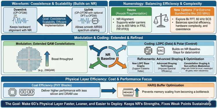
The goal is clear: make 6G’s physical layer faster, leaner, and easier to deploy. It keeps NR’s strengths while fixing its weak points in a sustainable way.
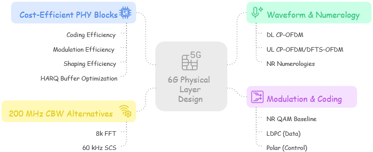
Waveform & numerology — DL CP-OFDM; UL CP-OFDM/DFTS-OFDM; reuse NR numerologies.- Ease MRSS/coexistence with NR.
- Support up to 400 MHz carriers.
Modulation & coding — NR QAM baseline; LDPC (data)/Polar (control).- Explore new base graphs for extreme rates.
- Coordinate shaping/constellation work with RAN4.
200 MHz CBW alternatives — 8k FFT or 60 kHz SCS (FR1/FR3).- Trade FFT size vs. SCS for implementation cost.
- Maintain coexistence with narrower carriers.
Cost-efficient PHY blocks — coding/modulation/shaping efficiency; HARQ buffer optimization.- Reduce silicon/DRAM footprint.
- Preserve link performance at lower complexity.
Synchronization & Initial Access
Synchronization and initial access in 6G must take a bigger step forward. Past generations improved slowly, but 6G targets energy efficiency and coverage strength from the start.
The design moves away from always-on, heavy signaling. It focuses on lean, smart signaling that lets networks sleep longer while keeping discovery and attachment reliable.
SSB periodicity will stretch beyond 20 ms. Sync bandwidth will shrink. Extra symbols or boosted DMRS will keep detection stable under tougher conditions. A coarser sync raster and limited-band options will cut UE search time, reduce power use, and simplify FR2 handling.
Initial access will be unified for all device types. It will scale smoothly from eMBB to IoT. Early MIMO and bandwidth signaling will be built in, with support for high Doppler and NTN.
Enhancements include more PRACH contention resources, new sync signal variants like NCD-SSB, and flexible periodicities around 40 ms. These reduce sync overhead for both the network and the UE while preserving detection and coverage.
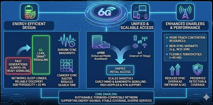
In short, 6G treats synchronization and access as core enablers. They support energy savings, stable coverage, and diverse services, setting up a more sustainable and forward-compatible network.
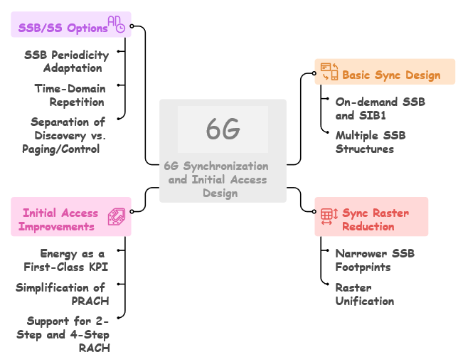
Basic Sync Design - On-demand SSB and SIB1 broadcasting to avoid unnecessary always-on signaling.
- Supports fast sync while minimizing idle-mode UE energy consumption.
- Enables on-demand SIB1 delivery to avoid repeated PBCH decoding.
- Multiple SSB structures: compact SSBs for IoT/low-power devices; richer SSBs for high-end devices.
- Low-power devices are not forced to detect all SSB types.
- Unified sync structure across device classes avoids fragmentation and keeps detection complexity low.
- Sync must accommodate minimum supported UE bandwidth (3–5 MHz operation).
Sync Raster Reduction - Narrower SSB footprints (~12 RB or fewer) reduce sync raster by up to ~80% in FR1-like bands.
- Smaller SSB widths shorten frequency scanning time and reduce UE energy consumption.
- Compact SSBs remain functional in narrow channelization (3–5 MHz).
- Raster unification made possible by dropping LTE-era 100 kHz raster constraints.
- Unified raster reduces the large number of raster points encountered in NR.
- Faster initial search, reduced blind detection, and simplified multi-band IA procedures.
- Sync raster aligns with MRSS to support NR→6G coexistence with minimal overhead.
Initial Access Improvements - Energy is a first-class KPI in initial access design.
- IA must avoid over-complexity and backward-compatibility burdens seen in 5G.
- Simplification of PRACH by removing rarely used formats while keeping deployment flexibility.
- PRACH design reduces blind tries and detection overhead.
- Supports both 2-step and 4-step RACH.
- 2-step RACH suited for low-latency or low-energy scenarios.
- 4-step RACH retained for deep coverage, weak signal, or high-mobility conditions.
- Initial access must maintain low complexity for low-power devices.
- IA design must jointly consider coverage, detection latency, and UE complexity.
SSB / Sync Signal Options - SSB periodicity adaptation between 20–160 ms based on load and energy targets.
- Short periods for high-load or mobility; long periods for low-load energy saving.
- Time-domain repetition of PSS/SSS/PBCH to improve one-shot detection under longer periodicity.
- Repetition compensates for narrower bandwidth and for higher mid-band pathloss.
- PBCH design enabling soft combining through time-invariant fields such as SFN.
- Separate discovery from paging/control functions.
- Lean SSBs used purely for discovery: coarse timing, frequency, and cell ID.
- Paging or SIB1 delivered via on-demand bursts to reduce always-on overhead.
- Prevents low-power UEs from unnecessary PBCH or paging decoding.
Advanced Considerations for Sync & IA - Sync must support consistent detection performance across MBB, RedCap, IoT, and CPE devices.
- Must enable reliable IA even with minimal UE RF/BB bandwidth.
- Initial access latency influenced by raster density, SSB size, and repetition strategy.
- Higher mid-band (FR3) detection challenges addressed by repetition and compact PBCH.
- Sync must maintain robustness under high pathloss frequencies (6–8+ GHz).
- Design supports smooth NR→6G migration, enabling hybrid sync during transition via MRSS.
- Initial access must be simple, deterministic, and energy-aware for all device categories.
Control Channels & Scheduling
Control channels and scheduling in 6G focus on simplicity and adaptability. The goal is to remove the overhead and fragmentation of past generations.
On the uplink, control signaling becomes leaner. The number of formats is reduced. Redundant overhead is cut. Instead of multiple PUCCH types, one baseline structure for scheduling requests and HARQ-ACK covers most needs. Long-term CSI moves to MAC-level control for better efficiency.
Downlink control follows the same idea. Lean, predictable signaling replaces complex structures. Features like a PCFICH-like channel, lean bandwidth parts, and semi-persistent scheduling tuned for AI/ML traffic reduce blind detection. This saves UE power and aligns better with traffic patterns.
Beyond simplification, control signaling in 6G brings deeper changes to robustness and privacy. DCI size is now decoupled from its content, so signaling formats become more flexible. Scrambling and better reference signal design add privacy and make the system more resistant to interference.
Control signaling will also become more asynchronous, so it works more like Layer-2. This reduces timing rigidity but keeps reliability. As a result, the system can react more smoothly to network variations.
It must also respond fast to bursts of mixed traffic. This is where fast bandwidth and multi-carrier adaptation help. A unified DCI framework allows near-instant activation or deactivation of carriers and bandwidth parts. This minimizes misalignment and keeps resources aligned with demand.
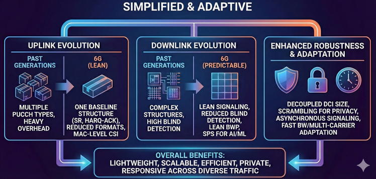
Together, these shifts make control channels lightweight and adaptive. They scale well from IoT to AI-driven traffic. As a result, 6G gains better efficiency, privacy, and responsiveness across the entire air interface.
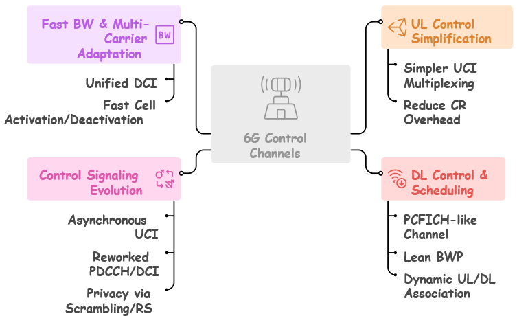
UL control simplification — simpler UCI multiplexing; reduce CR overhead.- Fewer PUCCH formats (e.g., SR + HARQ-ACK baseline).
- Move long-term CSI to MAC-CE.
DL control & scheduling — PCFICH-like channel; lean BWP; dynamic UL/DL association; semi-persistent DL for AI; dynamic CG-PUSCH.- Reduce blind detections and UE power.
- Fit control to AI/ML periodicity.
Control signaling evolution — asynchronous UCI (as L2); reworked PDCCH/DCI; privacy via scrambling/RS.- Decouple DCI size from content.
- Enhance PDCCH privacy/robustness.
Fast BW & multi-carrier adaptation — unified DCI; fast cell activation/deactivation.- React quickly to traffic bursts.
- Minimize misalignment between carriers.
MIMO, Beamforming & Reference Signals
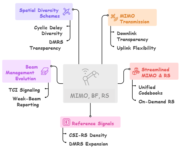
In 6G, MIMO, beamforming, and reference signals are not just add-ons. They are the core engine for scaling performance across devices, frequencies, and deployment scenarios.
On the transmission side, the design stays transparent and consistent for downlink. For uplink, it offers flexible closed-loop and open-loop modes. Non-precoded DMRS on PUSCH and PRB bundling improve channel estimation and make the uplink more robust. This ensures good CSI quality even for UEs under mobility.
MIMO must also scale widely. It should work for a few antennas on IoT devices and grow up to 1024 ports at base stations in FR3. So, the design needs to be streamlined. The codebook proliferation and always-on RS approach of 5G won’t work anymore.
Instead, unified codebooks and on-demand RS transmission will reduce overhead. This also prepares the system for near-field beamforming in higher mid-band and FR3 ranges.
Reference signals in 6G are being redesigned as multi-purpose tools. CSI-RS densities will increase, so the system can acquire channel state with higher accuracy. DMRS expansion up to 24 ports and flexible SRS settings will support advanced beam tracking, mobility, and positioning. This avoids the need for separate signal families.
TRS and SRS reuse will further cut signaling overhead. This creates a tighter and more energy-efficient design. Beam management will also become more unified. TCI signaling, weak-beam reporting, and conditional switching will enable fast beam recovery and keep MU-MIMO pairing stable.
Cross-band assistance adds extra strength. For example, FR1 can help guide beams in FR2 or FR3, so coverage and handover become more resilient. Spatial diversity schemes like cyclic delay diversity, when explicitly indicated, can bring back diversity gains for broadcast and control channels. At the same time, DMRS transparency and interference rank remain consistent.
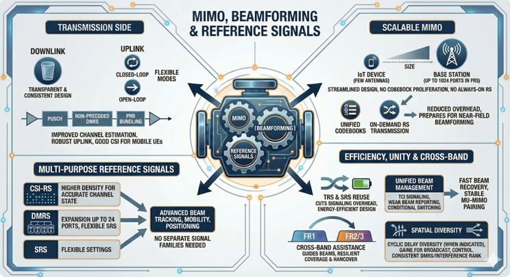
Overall, 6G treats MIMO, beamforming, and reference signals as one integrated system. They are scalable and efficient, so they support both peak performance and strong coverage in real deployments.
MIMO transmission — DL transparent + PRB bundling; UL closed/open-loop; non-precoded DMRS-PUSCH.- Scale across UE tiers and mobility.
- Improve uplink CSI fidelity.
Streamlined MIMO & RS — unified codebooks; 128→1024 ports; on-demand RS.- Cut always-on RS overhead.
- Prepare for FR3 near-field scaling.
Reference signals — CSI-RS up to 256; DMRS up to 24; TRS; multi-purpose SRS.- Enable advanced beam/CSI accuracy.
- Reuse RS for mobility/positioning where possible.
Beam management evolution — unified TCI; weak-beam reporting; FR1-assisted FR2/FR3; conditional switching.- Improve MU-MIMO pairing and stability.
- Speed beam recovery and handover.
Spatial diversity schemes — CDD with explicit indication; transparent DMRS consistency.- Add diversity for broadcast/control.
- Preserve interference rank assumptions.
Channel State Information (CSI) & Feedback
Channel State Information and feedback in 6G are being redesigned for simplicity, efficiency, and real-world robustness. In 5G, iterative codebook upgrades added complexity but saw limited adoption. So, 6G takes a cleaner path.
CSI reporting will rely on simplified codebooks. CQI will be more tightly linked to BLER targets. Some CSI may even be signaled at the PDCCH level. This lowers UE processing load and makes feedback quality match the needs of latency-sensitive and AI-driven traffic.
Feedback itself builds on NR Type-I PMI but becomes more compact. Higher-rank representations allow more MIMO layers without flooding the uplink with feedback. This keeps overhead low while enabling efficient use of large antenna arrays.
Another key shift in 6G is acknowledging bursty and sporadic uplink traffic. Traditional wideband, periodic CSI reports often arrive too late or waste resources when traffic is unpredictable. So, 6G moves to UL-centric CSI with dynamic uplink reference signals. This lets networks quickly stabilize modulation, coding, and precoding during traffic bursts.
Receiver design will also take on a bigger role. RX-centric approaches can better tolerate inter-layer interference and use more advanced baseband processing. As a result, the system can keep MIMO performance strong even when CSI is imperfect or fast fading breaks old assumptions.
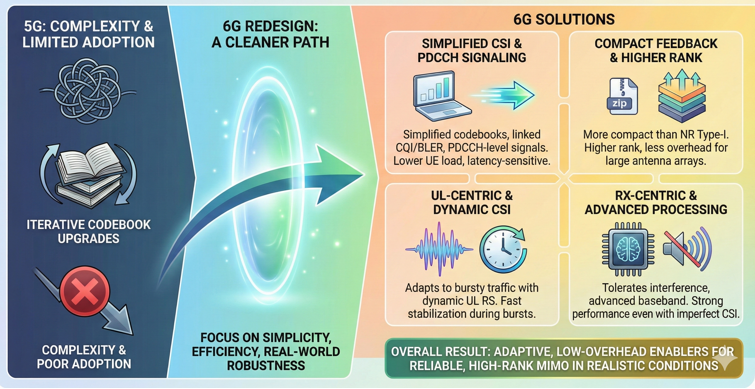
Together, these changes redefine CSI and feedback. They become adaptive, low-overhead enablers of reliable, high-rank MIMO in realistic deployment conditions.
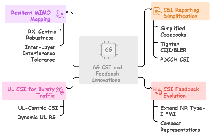
CSI reporting simplification — simplified codebooks; tighter CQI/BLER; PDCCH CSI.- Lower UE feedback complexity.
- Support stricter QoS (e.g., AI traffic).
CSI feedback evolution — extend NR Type-I PMI; compact representations.- Raise supported MIMO rank.
- Reduce uplink reporting overhead.
UL CSI for bursty traffic — UL-centric CSI; dynamic UL RS.- Adapt rapidly to sporadic loads.
- Stabilize MCS/precoding decisions.
Resilient MIMO mapping — RX-centric robustness; inter-layer interference tolerance.- Mitigate CSI errors and fast fading.
- Exploit advanced receiver capabilities.
HARQ & Retransmission Efficiency
In 6G, HARQ and retransmission are being redesigned for higher efficiency and lower latency. The old method of retransmitting an entire transport block when only a few code blocks fail is no longer practical in wideband, high-rate systems.
Instead, 6G introduces repair at the code block level. The scheduler can use precise redundancy signaling to resend only the parts that actually failed. This avoids unnecessary retransmissions and makes feedback channels more resilient.
With this finer control, networks can cut overhead, save spectrum, and speed up recovery. This is especially important for applications with tight latency requirements.
But improving efficiency alone is not enough. Feedback reliability also becomes a key design focus. Errors like NACKs misread as ACKs, timing mismatches, or bandwidth part desynchronization can hurt throughput more than missed retransmissions.
To prevent this, 6G introduces hardened feedback channels and tighter timing alignment. It also adds explicit fallback options that the scheduler can trigger when control mismatches happen.
![]()
These measures make HARQ both more precise and more robust. Retransmissions become surgical, and signaling becomes more reliable. As a result, 6G can deliver high spectral efficiency without losing consistency or service continuity.
![]()
HARQ retransmission efficiency — avoid full TB when few CBs fail; accurate redundancy signaling.- Lower wasted resources and latency.
- Provide CB-level repair guidance to scheduler.
Robust HARQ & scheduling — address NACK→ACK errors, ACK misalignments, BWP out-of-sync.- Harden feedback channels and timing.
- Design fallbacks for control mismatch.
Mobility, Resilience & Security
Mobility, resilience, and security in 6G are being treated as one integrated foundation. The goal is to build a network that moves smoothly and stays strong against disruptions.
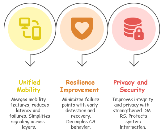
The mobility framework will unify mechanisms that are now split across layers. It combines L3 mobility, conditional handover, link and beam management, and wake-up radio–assisted measurements into one design. By cutting down on signaling handshakes and guiding beam and cell selection intelligently, it can lower handover latency and reduce failures. This matters most at cell edges and in high-mobility cases.
Resilience extends this logic beyond mobility. The architecture avoids single points of failure and reacts fast to problems. A failing PCell will no longer bring down an entire carrier aggregation group. Secondary cells can stay active independently. Early health checks, quick instability detection, and recovery paths make performance dips short and almost invisible to users.
Security and privacy are also built in from the start. Integrity protection for broadcast information like MIB and SIB makes spoofing and tampering much harder. New PDCCH designs use scrambling and obfuscation to limit what eavesdroppers can learn. Stronger DMRS structures protect control and reference signals under hostile conditions.
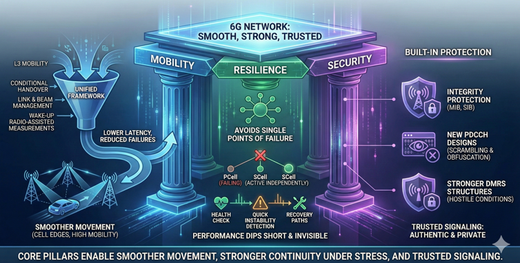
In short, 6G makes mobility, resilience, and security core pillars. It enables smoother movement through the network, stronger continuity under stress, and trusted signaling that stays both authentic and private.
Unified mobility framework — merge L3 mobility, CHO, LTM, beam mgmt; WUR-assisted measurements.- Reduce handover latency and failures.
- Simplify mobility signaling across layers.
Resilience — minimize single points of failure; early failure detection/recovery.- Decouple CA behavior from single PCell.
- Introduce health checks and rapid recovery.
Privacy & security — integrity for MIB/SIB; improved PDCCH privacy; strengthened DM-RS.- Protect system information authenticity.
- Limit observability of control activity.
Coverage Enhancement
Coverage in 6G is a baseline design goal. It is not a feature added afterward. The primary motivation is the uplink bottleneck seen in today’s mid-band deployments. Downlink grows fast, but devices cannot send back enough data. So, 6G starts with a coverage-native foundation.
Uplink budgets get stronger. This comes from higher UE transmit power, low-PAPR waveforms, uplink carrier aggregation, and uplink MIMO. These combine with SBFD in mid-band. As a result, edge reliability improves for AI inference, XR streaming, and other uplink-heavy applications.
Smarter coverage tools add an extra layer. Generalized TBoMS and scheduler-aware repetition schemes make transmissions more resilient. Enhanced random access increases initial access success when the signal is weak. Early Msg3-based power headroom reporting gives the scheduler more information before the link becomes stable.
Uplink-centric coverage also ties into AI-driven services. PUSCH/PUCCH/PRACH repetitions stabilize the early phases of UL transmission. Early power-control information allows more accurate adaptation in the critical first moments of connection setup.
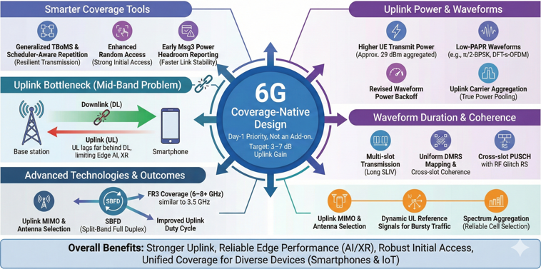
Overall, 6G coverage enhancements remove current mid-band limits. They give stronger uplink, more reliable edge performance, and more robust initial access.
Coverage-native design in 6G - Covers 6G as a Day-1 priority, not an add-on.
- Removes mid-band uplink bottlenecks where UL lags far behind DL.
- 6G aims for 3–7 dB uplink coverage gain over current systems.
- Coverage evaluation follows a two-step method:
- Step 1: Required SINR for each physical channel
- Step 2: Convert SINR to link budget metrics like MCL(Maximum Coupling Loss)/MIL(Maximum Isotropic Loss)/MPL(Maximum Path Loss)
- Coverage target considers frequency, deployment scenario, and service UL/DL targets.
Uplink power enhancement - Higher UE transmit power classes for upper mid-band frequencies.
- Smartphone uplink target of approximately 29 dBm aggregated across 4 antennas.
- Includes study of power-class-free operation and revised waveform power backoff definitions.
Low-PAPR uplink waveforms - Use of DFT-s-OFDM with low-PAPR modulation such as π/2-BPSK.
- Revisiting MPR table to unlock full low-PAPR potential.
- Study tunable waveform families that balance PAPR and spectral efficiency.
Waveform duration & coherence - Support multi-slot uplink transmissions via long SLIV.
- Uniform DMRS mapping across multi-slot durations.
- Maintain cross-slot phase coherence for robust channel estimation.
Cross-slot PUSCH with RF glitch RS - Handles RF discontinuities at slot boundaries caused by PA/LNA updates.
- Low-overhead RF glitch reference signals are inserted near slot boundaries.
- Enables joint DMRS processing to improve uplink robustness.
Uplink carrier aggregation (UL CA) - Removes traditional sum-power constraints across aggregated uplink carriers.
- Allows true power pooling across bands.
- Improves uplink stability across mixed FR1 and higher mid-band deployments.
- Requires better network visibility into per-band UE power headroom.
- Inter-band uplink aggregation is treated as a baseline requirement.
Uplink MIMO & antenna selection - Network-assisted UL antenna selection when UL/DL reciprocity does not hold.
- Coherent uplink MIMO designed under practical phase-drift and device limitations.
- Dynamic uplink reference signals for fast CSI updates and rapid MCS/precoding adjustments.
UL CSI for bursty traffic - NR SRS-based CSI is too slow for bursty or sporadic uplink traffic.
- 6G introduces flexible uplink reference signals for rapid CSI acquisition.
SBFD (Split-Band Full Duplex) - Improves uplink duty cycle compared to TDD, yielding several dB of uplink gain.
- Essential for strong uplink coverage in 6–8+ GHz mid-band.
- Operates best in greenfield deployments without legacy coexistence constraints.
- Treated as a Day-1 uplink coverage enabler in 6G.
FR3 (6–8+ GHz) coverage targets - Goal: achieve uplink coverage similar to today’s 3.5 GHz systems.
- Enabled through higher UL power, SBFD operation, and large-array MIMO.
- Smartphone requirements include 4Tx/8Rx capability and support for up to 400 MHz bandwidth.
Smarter repetition & TBoMS - Scheduler-aware repetition patterns improve robustness for weak-signal uplink.
- Generalized TBoMS(Transport Block over Multiple Slots) enables smarter repetition bundling for low-SNR transmissions.
Enhanced Random Access coverage - Multi-slot Msg1/PRACH repetitions strengthen initial access in weak coverage.
- Scheduler-aware RA mapping improves reliability at cell edges.
- RA enhancements account for wider delay spreads and propagation in higher bands.
Msg3 Early Power Headroom Reporting - Early Msg3-based PHR gives the network quick insight into UE uplink capability.
- Stabilizes early stages of uplink transmission.
Coverage in mobility / MRSS - MRSS enables NR and 6G to operate within the same spectrum resources.
- Avoids LTE-CRS complexity seen in earlier migration schemes.
- Efficient control-channel coexistence improves edge coverage.
- Allows immediate 6G coverage using existing 5G radio units.
Spectrum aggregation for coverage - CA used to select the most reliable uplink cell across bands.
- Relaxed uplink power rules enable stronger multi-band uplink coverage.
- 6G extends these mechanisms to support broader uplink paths.
Coverage for IoT / LPWA devices - Coverage-native design applies to IoT and LPWA device classes.
- Uplink data rates down to around 1 kbps supported at deep coverage.
- 5 MHz baseline bandwidth (with optional 3 MHz) aligns IoT with standard 6G SSB layout.
- A single carrier should serve both IoT and eMBB devices with the same coverage radius.
Synchronization signal coverage - 6G sync raster must reduce scanning points for faster acquisition.
- Improves initial cell search under weak signal conditions.
Unified device-type coverage - All device types share identical coverage targets.
- Only service data rates differ between device categories.
Control-channel coverage - 6G treats control-channel coverage independently from data-channel coverage.
- Ensures reliability for voice, positioning, and initial access procedures.
New duplexing for coverage - Duplexing modes aim to reduce DL-to-UL interference at higher frequencies.
- Leverages large-array MIMO to offset coverage losses in upper mid-band.
Scheduling behavior for coverage - Flexible uplink repetition patterns improve reliability.
- Aligns scheduling with per-carrier power availability.
- Switches efficiently between narrowband and wideband uplink modes.
Uplink-first stability in early access - PUSCH/PUCCH/PRACH repetitions stabilize early access phases.
- Ensures reliable uplink establishment at deep cell-edge.
Power Efficiency
Energy efficiency stands as the second core design axis in 6G. The objective is an ultra-lean network where every layer avoids unnecessary always-on behavior. This reduces energy at both the network side and the device side.
On the network side, always-on signaling shrinks. SSB periodicity extends up to 160 ms. Wake-up signals allow paging without continuous scanning. DRX switching keeps idle UEs attached with almost no energy drain. The network stays responsive even with long sleep cycles.
On the UE side, 6G expands NR power-saving techniques. Sparse PDCCH monitoring reduces control-channel checks. Bandwidth-part adaptation keeps only the required spectrum active. Grant-free uplink bursts let UEs send short packets without full scheduling. These reduce both control-plane and uplink overhead. UEs sleep longer between network interactions, so battery life increases.
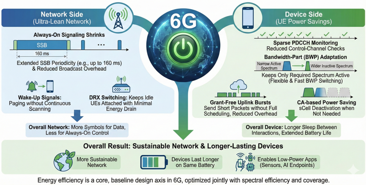
Together, these mechanisms create an energy-efficient ecosystem. The network becomes more sustainable. Devices last longer on the same battery. New low-power applications, such as sensors and lightweight AI endpoints, become practical.
Energy-efficient 6G design principles - Energy efficiency is a core design axis from the start.
- Targets both network energy savings and UE power savings.
- Energy efficiency considered together with spectral efficiency, coverage, and complexity.
Network energy efficiency (ultra-lean network) - Minimize always-on signaling and broadcast overhead.
- More symbols are used for data rather than always-on control.
- SSB periodicity can be extended (e.g., up to 160 ms) to reduce idle scanning energy.
- Longer SSB offsets increase discovery latency, so sync design must be jointly optimized.
- Sync raster, periodicity, and resource structure must support both energy efficiency and fast access.
- Multi-RAT spectrum sharing aims to reduce overhead compared to legacy approaches.
Bandwidth adaptation & UE energy savings (BWP evolution) - BWP aligns UE active bandwidth with traffic needs to reduce power consumption.
- Traditional BWP switching can cause misalignment, limiting aggressive power saving.
- 6G keeps flexible NR-style BWP but improves reliability and speed.
- Two adaptation mechanisms:
- A reliable but slower mechanism for long or medium-term adaptation.
- A fast DCI-based mechanism for short-term adaptation inside active bursts.
- Fast mechanism adjusts:
- Maximum bandwidth
- Maximum rank
- Minimum scheduling offset
- PDCCH monitoring periodicity
- Design ensures at least some PDCCH candidates are always decodable even during transitions.
CA-based power saving (multi-carrier operation) - CA provides tools such as cross-carrier scheduling and aligned DRX cycles.
- sCell addition, release, activation, and deactivation used to manage UE power.
- When bandwidth is not needed, secondary carriers can be deactivated to reduce UE power drain.
- Current activation/deactivation is slow, causing schedulers to keep sCells on longer than required.
- 6G should speed up CA configuration and sCell transitions.
- Directional activation (DL-only activation for DL bursts) enables power savings.
- CA works together with BWP so UE can stay narrow most of the time and widen bandwidth only briefly.
Network-side DRX and wake-up signaling - Network adopts ultra-lean DRX-friendly behavior.
- Wake-up signals reduce the number of paging scans needed by UEs.
- DRX switching keeps idle UEs connected while minimizing energy consumption.
- Goal is to minimize idle-mode energy without harming access latency.
UE-side power saving modes - More aggressive DRX than NR where traffic allows.
- Sparse PDCCH monitoring reduces unnecessary UE activity.
- BWP adaptation keeps UE in narrow operation by default.
- BWP widens quickly for bursts, then shrinks again.
- Grant-free uplink bursts allow small data transmissions without full scheduling overhead.
- Grant-free reduces control-plane wakeups and saves UE power.
Sync signal design with energy in mind - Sync design must balance energy, detection performance, and latency.
- Unified sync structure across device types, including IoT.
- Minimum 5 MHz baseline channel, with possible support for 3 MHz low-power devices.
- PBCH design can separate SFN from other fields, allowing soft combining.
- Soft combining lowers the number of decodes for weak-RF devices, reducing UE energy consumption.
Trade-offs in SSB periodicity for energy savings - Longer SSB periods reduce scanning energy but increase discovery latency.
- Energy savings depend on load, architecture, and traffic model.
- 6G requires load-aware strategies instead of one fixed SSB period.
Specification streamlining for power optimization - Reduce optional modes and fragmentation.
- Mainstream key power-saving mechanisms as baseline features.
- Streamlined features help UE and gNB implementations optimize power consistently.
- Fewer variants reduce complexity and improve real-world energy efficiency.
Overall result - Network becomes more energy-efficient and sustainable.
- UE battery life extends through DRX, BWP adaptation, and CA-based power control.
- Low-power services become feasible, including sensor-type and background devices.
- Energy efficiency becomes a fundamental pillar across the whole 6G ecosystem.
Channel and Antenna Modeling
Evaluation assumptions are the bedrock of the 6G study. To ensure the new air interface works across diverse bands—specifically the new upper mid-band (7–15 GHz)—channel and antenna modeling has moved beyond simple abstractions. The goal is to create a unified simulation framework that accurately reflects physical reality for both terrestrial and non-terrestrial deployments, ensuring that performance gains are genuine rather than artifacts of simulation.
Base station modeling scales up significantly to support the "Upper Mid-band." Evaluation configurations now specify massive element counts, ranging from 128 to 256 elements (and up to 1024 for higher bands). The architecture is defined by precise panel parameters (M, N, P, Mg, Ng) to support advanced MIMO and beamforming. On the device side, the "one-size-fits-all" model is discarded. Distinct antenna assumptions are defined for Handhelds (e.g., 1T2R or 2T4R), High-power CPEs for Fixed Wireless Access (FWA), Vehicles, and constrained IoT devices, ensuring the link budget reflects the specific capabilities of each vertical.
The channel models themselves are evolving to capture new physical phenomena. While TR 38.901 remains the baseline, 6G necessitates extensions. High-frequency, large-aperture arrays introduce Near-Field (radiative near-field) propagation effects which must be modeled. Furthermore, Spatial Non-Stationarity is introduced, where the channel impulse response varies across the physical extent of a large antenna array. For Non-Terrestrial Networks (NTN), specific models for LEO satellite dynamics, large delays, and varying Doppler shifts are integrated alongside distinct satellite antenna types (Reflector vs. Phased Array).
Together, these modeling enhancements allow for a rigorous assessment of 6G technologies, from ISAC sensing accuracy to extreme coverage in rural scenarios.
Base Station Antenna Scaling – 128 to 256+ elements; Panel-based design.- Support higher frequencies (7–15 GHz).
- Enable accurate simulation of massive MIMO and beamforming.
Device-Specific Modeling – Handheld, CPE, Vehicle, IoT differentiation.- Define specific Tx/Rx counts (e.g., 2T4R for handheld).
- Tailor link budgets to specific form factors and power limits.
Advanced Channel Physics – Near-field propagation; Spatial non-stationarity.- Account for large antenna apertures where plane-wave assumptions fail.
- Model channel variations across the physical array surface.
NTN & Satellite Modeling – LEO dynamics; Reflector vs. Phased Array.- Simulate high Doppler and long propagation delays.
- Differentiate between satellite antenna architectures.
Sensing (ISAC) Integration – RCS modeling; Clutter environments.- Incorporate target reflection properties into the channel model.
- Evaluate sensing accuracy alongside communication throughput.
Network Controlled Repeaters (NCR) & Reconfigurable Intelligent Surfaces (RIS)
Network-Controlled Repeaters (NCR) and Reconfigurable Intelligent Surfaces (RIS) are identified as critical tools for cost-effective coverage expansion and energy efficiency in 6G, particularly to address the challenges of higher frequency bands like FR2 and FR3. While NCRs were introduced in 5G Rel-18, their commercialization has been limited, and 6G aims to integrate them, along with RIS, from the initial design phase to ensure better support and standardization.
RIS offers a low-energy, low-cost method to dynamically reshape the radio propagation environment, enhancing coverage in "dead zones" such as dense urban canyons or extending cell edges. To make RIS effective, 6G must define standardized interfaces and control mechanisms for passive and semi-passive elements, preventing them from becoming proprietary "black boxes".
The deployment of these relay nodes necessitates a flexible beam management framework capable of handling the increased number of beam paths and dynamic network topology. Additionally, specific improvements are needed for NCRs, such as better positioning support, to facilitate their commercial adoption.
Early Standardization – Incorporate NCR and RIS support from the initial stages of 6G to enable cost-effective coverage enhancement.- Avoid late-stage introduction that hinders commercial deployment.
Dynamic Environment Shaping – Use RIS as a low-cost/low-energy method to dynamically enhance coverage and capacity.- Target challenging environments like dense urban areas and cell edges.
Standardized Control Interfaces – Define standard interfaces for RIS to ensure interoperability and network control.- Support passive and semi-passive RIS elements.
Flexible Beam Management – Adapt beam management to accommodate the dynamic addition of relay nodes and the resulting increase in beam paths.- Ensure robust and low-latency beam switching.
Commercialization Improvements – Address remaining aspects for NCR commercialization, such as positioning provision.
AI/ML Integration
AI and machine learning are built into 6G from the start. They are not just optimization tools but core parts of the air interface.
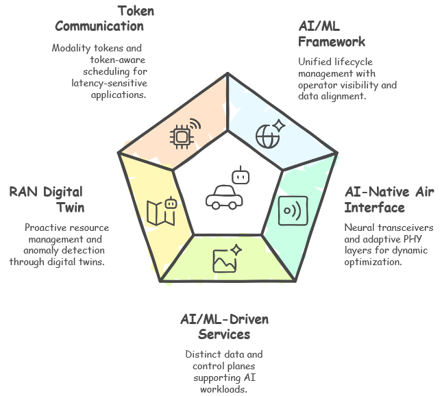
At the framework level, 6G introduces a unified lifecycle for AI. Operators can see, manage, and interact with AI pipelines directly. Standard hooks define how models are trained, deployed, and updated. Privacy and security controls are aligned with the sensitive data these models use. AI traffic is treated as its own category. Model updates and token-based interactions follow their own QoS rules. This prevents AI workloads from competing blindly with user traffic.
On the physical layer, the network moves to an AI-native air interface. Neural transceivers, pilotless or superimposed reference designs, and AI-based interference prediction make the PHY adaptive. It can co-optimize coding, modulation, and RS density in real time. This dynamic behavior naturally extends to higher layers through AI-driven services. Net4AI focuses on serving AI traffic. AI4Net applies AI to control the network. Together, they create a closed loop where AI both drives and uses the air interface.
The RAN digital twin is a key enabler. By merging sensing, CSI, and telemetry, operators can maintain local and network-wide twins. These twins anticipate issues before they affect users, manage resources proactively, and detect anomalies early.
Communication itself may shift to token-based exchanges. Latency-sensitive AI workloads use tokens to signal their modality—human, robotic, or agent. Token-aware scheduling, HARQ, and QoS let the network treat different traffic types appropriately. Ultra-low-latency control loops get the priority they need, while less urgent traffic uses leftover resources efficiently.
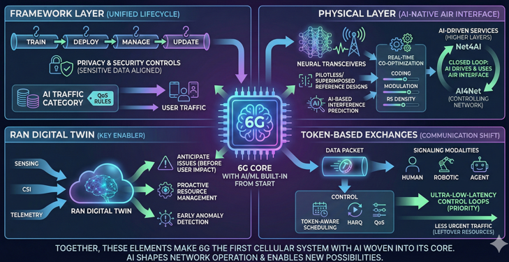
Together, these elements make 6G the first cellular system with AI woven into its core. AI shapes both how the network operates and what it can enable.
6G AI/ML framework — unified LCM; operator-visible data; separate AI traffic.- Standardize model lifecycle hooks.
- Align privacy/security for data collection.
AI-native air interface — neural Rx/Tx; pilotless/superimposed pilots; anomaly/interference prediction.- Co-optimize PHY blocks with learning.
- Adapt RS/pilot density on demand.
AI/ML-driven services — Net4AI & AI4Net; support model updates and token traffic.- Expose AI data/control planes distinctly from UP/CP.
- Prioritize latency/jitter for AI loops.
RAN digital twin — local→network-wide twins for optimization and services.- Fuse sensing/CSI/telemetry streams.
- Drive proactive planning and anomaly detection.
Token communication — modality tokens; token-aware scheduling/HARQ/QoS.- Latency tiers (human/robot/agent) guide QoS.
- Handle streaming vs. burst token arrivals.
New Service Types & Verticals (IoT, XR, FWA, etc.)
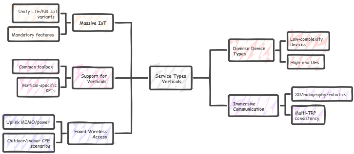
In 6G, service types and verticals are part of the core design, not afterthoughts added later. The goal is to build a single global framework that supports massive IoT from the start. This resolves the fragmentation left by LTE-M, NB-IoT, and NR IoT variants.
Mandatory IoT features like multicast and group messaging become native capabilities. So, low-cost devices can work seamlessly around the world. An IoT profile is planned with modest requirements: 3–5 MHz bandwidth, single-antenna HD-FDD operation, and 1–5 Mbps throughput. This keeps devices affordable and power-efficient while giving them a clear upgrade path from LTE Cat-M.
Device diversity is also a central focus. The design supports everything from tiny sensors and wearables to XR headsets and brain–computer interfaces. It scales from narrowband allocations to 400 MHz channels. Features like eDRX, wake-up radio, and extended maximum coupling loss keep small devices efficient and connected. At the same time, high-end UEs can use wider bandwidths and richer capabilities.
This approach applies to verticals as well. Instead of separate standards for IoT, XR, or RedCap, 6G offers one common toolbox. Vertical-specific KPIs can be configured, but the air interface stays unified.
Immersive services push these principles even further. XR, holography, and robotics need high uplink capacity and multi-TRP consistency to keep interaction stable and QoE high. Fixed Wireless Access (FWA) is also built in. Uplink MIMO and power are dimensioned for CPEs to handle asymmetric traffic patterns in homes and enterprises.
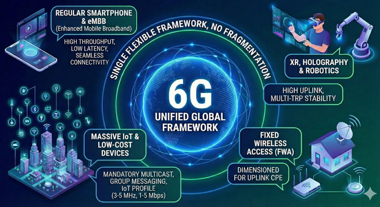
Together, these choices give 6G a single, flexible framework. It supports everything from basic sensors to demanding immersive applications, avoiding the fragmentation that slowed adoption in earlier generations.
6G massive IoT baseline — single global solution; mandatory features.- Unify fragmented LTE/NR IoT variants.
- Include multicast/group messaging support.
IoT migration profile — 3–5 MHz, 1–5 Mbps, single-antenna, HD-FDD.- Target LTE Cat-M migration path.
- Keep cost/energy within IoT constraints.
Diverse device types & IoT — low-complexity to high-end UEs; eDRX/WUR/extended MCL.- Scale bandwidth from 3 MHz to 400 MHz.
- Support wearables, XR, BCI, sensors.
Support for verticals — unified framework for IoT/RedCap/XR.- Common toolbox with vertical-specific KPIs.
- Avoid vertical-specific forks in the standard.
Immersive communication — XR/holography/robotics; UL-heavy KPIs; multi-TRP consistency.- Low-latency uplink for interaction loops.
- Stable QoE via coordinated TRPs.
Fixed Wireless Access — account for FWA traffic; UL MIMO/power for CPEs.- Dimension uplink for asymmetric loads.
- Optimize for outdoor/indoor CPE scenarios.
Integrated Sensing & Communication (ISAC/ISPC)
In 6G, Integrated Sensing and Communication (ISAC) is treated as a core air-interface function, not a side feature. The goal is to use the same spectrum, waveforms, and hardware for both communication and sensing, so networks don’t need separate infrastructure.
This shift starts at the physical layer. Monostatic designs—both full-duplex and pulsed—along with bistatic configurations are under study. The key idea is to share RF chains to lower cost and shrink the hardware footprint. Self-interference is the main technical challenge, especially in full-duplex sensing. Overcoming it is essential for stable ISAC operation.
A major enabler is reference signal reuse. Instead of adding heavy sensing-specific signaling, 6G leverages SSB, CSI-RS, and SRS in FR1 and FR3. Dedicated RS is reserved mainly for FR2, where higher angular resolution is required. Even user-to-user sensing is being explored under the same principle: minimize RS overhead while keeping communication reliable. This keeps the interface lean while maintaining sensing accuracy.
The ISAC vision goes beyond the PHY layer. Sensing-as-a-Service is expected to emerge as a new operator offering. Networks will expose detection, tracking, and situational awareness through standardized APIs. This creates new business opportunities, but it also requires strict privacy, policy, and security controls to protect sensing data.
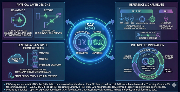
In short, ISAC in 6G is both a technical and service-layer innovation. It combines connectivity and environmental awareness into a single, efficient, and secure network capability.
ISAC design — monostatic (FD/pulsed) & bistatic; common waveform/hardware.- Share RF chains to reduce cost.
- Address self-interference for FD sensing.
Common RS for comms & sensing — SSB/CSI-RS/SRS in FR1/FR3; dedicated RS mainly in FR2; study U2U.- Minimize added RS overhead.
- Preserve communication performance.
Sensing-as-a-Service — operator exposure/monetization.- APIs for detection, tracking, situational awareness.
- Privacy and policy controls for shared data.
NTN (Non-Terrestrial Networks) Integration
For 6G, NTN integration is treated as a natural extension of terrestrial networks, not a separate track. Past experience with 5G showed that many NTN features—like coverage extensions, RACH-less handover, and extended HARQ—ended up benefiting terrestrial networks too. So, 6G begins with a unified TN/NTN design philosophy.
This means common mechanisms for search, initial access, HARQ, and even multi-satellite support. Only a few NTN-specific adaptations are added where absolutely necessary.
Several challenges shape this design. Delay and Doppler variations, especially from LEO satellites, require stronger uplink timing control, PRACH repetitions, and more robust random access. In GNSS-limited situations, terminals may need to run fully GNSS-free. So, frequency offset handling, time alignment, and beam or AoD–based mobility become critical.
Beamforming and mobility must also keep service continuous as satellites move in and out of view within minutes. The guiding idea is simple: reuse terrestrial mechanisms wherever possible, define lightweight NTN deltas, and keep one unified baseline.
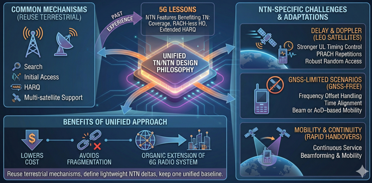
This approach lowers cost, avoids ecosystem fragmentation, and turns NTN into an organic extension of the 6G radio system instead of a parallel silo.
Unified TN/NTN design — unified search, IA, HARQ, bands; multi-satellite; CA; GNSS-less options.- Reuse TN mechanisms where feasible.
- Define minimal NTN-specific deltas.
NTN aspects — PRACH reps with FO/TA; AoD-based mobility; delay/Doppler handling.- Robust access in GNSS-limited scenarios.
- Mitigate mobility with beam/AoD support.
Device Types & Capability Frameworks
In 6G, device diversity is treated as a core design axis, not an afterthought. The standard is built as one modular framework that scales from basic sensors to advanced immersive headsets. The idea is simple: one common toolbox for all verticals, not fragmented RATs or separate profiles.
Features scale by capability tiers. Low-power IoT devices focus on coverage and battery life. High-tier UEs unlock full eMBB or URLLC performance. This keeps interoperability intact even as device complexity varies widely.
The design supports a broad range of channel bandwidths. IoT can run on as little as 3 MHz, while XR or brain–computer interfaces can use up to 400 MHz. Graceful degradation is a key principle. Low-tier devices operate efficiently without carrying the burden of high-end features. High-tier devices, on the other hand, can scale throughput and latency to match their hardware and use cases.
FR2 devices are a special focus. The framework expects single-panel UE designs to lower cost and simplify manufacturing. Power efficiency and reliability are balanced carefully. Even with leaner hardware, smart beam management and adaptive signaling keep mmWave links strong.
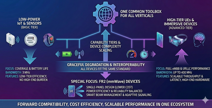
Altogether, the 6G device and capability framework brings forward compatibility, cost efficiency, and scalable performance into one ecosystem. It ensures that every device—from a tiny sensor to an advanced XR headset—fits into the same standard.
Scalable, modular design — min KPIs (massive IoT) → eMBB/URLLC; single toolbox.- One spec set for all verticals.
- Scale features by device capability tiers.
Diverse devices & channel bandwidth — 3–400 MHz CBW across AR/VR/wearables/BCI/IoT.- Balance power vs. throughput per device class.
- Enable graceful degradation on low-tier UEs.
FR2 device design — single-panel UE trade-offs for cost/power vs. reliability.- Reduce UE BOM and complexity.
- Maintain link robustness at mmWave.
Testing, Certification & Standardization Processes
In 6G, testing, certification, and standardization are being redesigned to avoid the fragmented, option-heavy model of past generations. The focus is on global minimum capability sets that every device and network must support. This creates a tighter baseline and ensures interoperability across regions and vendors.
Certification is treated as a binding process between networks and UEs. It checks not just standalone compliance but also how well devices and networks work together in real deployments. By making key features mandatory and tracking their adoption from the first release, 6G avoids the trap of optional features that never gain traction.
This disciplined approach shortens time-to-market and reduces fragmentation. It also gives operators and vendors more confidence that deployed features will actually be supported in the field.
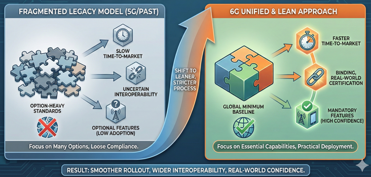
In short, 6G certification is leaner, stricter, and more globally harmonized. It ties standardization directly to practical deployment, ensuring smoother rollout and wider interoperability.
New testing & certification paradigm — global minimum capability sets; binding network/UE certification; avoid excessive options.- Track deployment of mandatory features.
- Improve interoperability and time-to-market.
Reference
- RAN1#122 (2025-08-25 - Bengaluru(IN))
- RP-251881 — New SID: Study on 6G Radio — NTT DOCOMO (Moderator)
- R1-2506303 — RAN1 workplan for Rel-20 Study of 6GR — NTT DOCOMO, China Mobile, AT&T, Vodafone
- R1-2505125 — Nokia Views on 6G Radio Air Interface — Nokia
- R1-2505143 — High level views on 6GR air interface — FUTUREWEI
- R1-2505170 — Spreadtrum overview on 6GR air interface — Spreadtrum, UNISOC
- R1-2505181 — Overview of 6GR air interface — Huawei, HiSilicon
- R1-2505263 — Overview of 6GR Air Interface — Google
- R1-2505285 — Discussion on the overview of 6GR air interface — TCL
- R1-2505295 — Outline and highlight of 6GR air interface — CATT, CICTCI
- R1-2505414 — Overall design considerations on 6GR air interface — vivo
- R1-2505461 — 6GR air interface design overview — Xiaomi
- R1-2505509 — High-level views on 6GR — ZTE Corporation, Sanechips
- R1-2505511 — Overview proposal of 6GR air interface — Panasonic
- R1-2505516 — Overview of 6GR air interface — China Telecom
- R1-2505519 — Overview of 6GR air interface — NVIDIA
- R1-2505582 — Design of 6GR air interface — Samsung
- R1-2505612 — Tiami Networks views on 6G Radio Interface — Tiami Networks
- R1-2505627 — Clarifying MRSS Requirement for 6G Waveforms — Cohere Technologies
- R1-2505648 — Overview of 6GR air interface — Pengcheng Laboratory, BUPT
- R1-2505650 — Overview of the 6G air interface — Ericsson Telecom S.A. de C.V.
- R1-2505655 — Views on 6GR air interface — Fainity Innovation
- R1-2505673 — Initial Views on 6GR Air Interface — Ofinno
- R1-2505755 — Overview of 6GR: A unified air interface with modular design — OPPO
- R1-2505763 — Overview of 6GR air interface — InterDigital, Inc.
- R1-2505771 — Intel’s view on 6GR air interface — Intel
- R1-2505790 — Overview of 6GR air-interface — Lenovo
- R1-2505798 — Overview of 6GR air interface — KT Corp.
- R1-2505813 — Overview of 6GR air interface — Fraunhofer IIS, Fraunhofer HHI
- R1-2505854 — Views on overall design and techniques for 6GR air interface — LG Electronics
- R1-2505865 — 6G Radio Access Needs Overview — T-Mobile USA Inc.
- R1-2505911 Revised in R1-2506396 — Overview of 6GR air interface — Apple
- R1-2505933 — Overview of 6GR air interface — NEC
- R1-2505957 — Overview on 6G Air interface — Tejas Network Limited
- R1-2505967 — Fujitsu’s view of 6GR air interface — Fujitsu
- R1-2505982 — Overview of 6GR air interface — Sharp
- R1-2506002 — Discussion on overview of 6GR air interface — HONOR
- R1-2506018 — Overview of 6GR air interface — MediaTek Inc.
- R1-2506063 — Overview of the 6GR air interface — ETRI
- R1-2506095 — Overview of 6GR air interface — CMCC
- R1-2506116 — Overview of 6GR air interface — Sony
- R1-2506139 — Discussion on the Overview of 6GR Air Interface — Rakuten Mobile, Inc
- R1-2506150 — Views on overview of 6GR air interface — SK Telecom
- R1-2506156 — Physical-layer security considerations for 6G Radio (6GR) — ST Engineering iDirect, Philips
- R1-2506164 — Discussion on 6G Radio — TOYOTA Info Technology Center
- R1-2506216 — Overview of 6GR air interface — Qualcomm Incorporated
- R1-2506238 — Views on 6GR Air Interface Design — AT&T, Ericsson
- R1-2506262 — Views on 6G AI-native System Design — CAICT
- R1-2506304 — Discussion on overview of 6GR air interface — NTT DOCOMO, INC.
- R1-2506323 — Overview of 6G Radio air interface — WILUS Inc.
- R1-2506325 — General aspects of 6G IoT and NTN — Nordic Semiconductor ASA
- R1-2506326 — Discussion on Overview of 6GR air interface — China Unicom
- R1-2506327 — Overview of 6GR air interface — THALES
- R1-2506335 — Views on 6GR air interface — CSCN
- R1-2506358 — Overview of 6G Air Interface — CEWiT
- R1-2506365 — Overview of 6GR air interface — KDDI Corporation
- R1-2506368 — Views on 6GR air interface design criteria — NICT
- R1-2506394 — Views on 6G PHY choices — BT, Orange, Vodafone, Deutsche Telekom, Turkcell, KPN
- RAN1#123 (2025-11-17 - Dallas(US)
- R1-2508314 — LS on 6GR system parameter evaluations — RAN4, Huawei
- R1-2508320 — More high level views on the 6GR air interface — FUTUREWEI
- R1-2508321 — Evaluation assumptions for 6GR air interface — FUTUREWEI
- R1-2508334 — Nokia Views on Selected Aspects of 6G Radio Air Interface — Nokia
- R1-2508335 — On Evaluation Assumptions for Study of 6G Radio Air Interface — Nokia
- R1-2508352 — Overview of the 6G air interface — Ericsson
- R1-2508386 — Overview of 6GR air interface — Spreadtrum, UNISOC
- R1-2508392 — Discussion on AIML in 6GR interface — Spreadtrum, UNISOC
- R1-2508430 — Overview of 6GR air interface — vivo
- R1-2508431 — Evaluation methodology and assumptions for 6GR air interface — vivo
- R1-2508453 — Overview of 6GR air interface — CMCC
- R1-2508454 — Discussion on evaluation assumptions for 6GR air interface — CMCC
- R1-2508472 — Overview of 6GR air interface — THALES
- R1-2508473 — Discussion on Evaluation Assumptions and Performance Evaluation for ISAC — Tiami Networks
- R1-2508474 — Discussion on Overview of 6GR Air Interface — Tiami Networks
- R1-2508476 — Overview of 6GR air interface — Fraunhofer IIS, Fraunhofer HHI
- R1-2508515 — AI/ML for 6G Air Interface — InterDigital, Inc.
- R1-2508523 — Overview of 6GR air interface — TCL
- R1-2508524 — Discussion on evaluation assumptions for 6GR air interface — ZTE Corporation, Sanechips
- R1-2508560 — Overview of 6GR air interface — NEC
- R1-2508562 — Feature Lead summary #1 on 6G waveform — Moderator (Nokia)
- R1-2508563 — Feature Lead summary #2 on 6G waveform — Moderator (Nokia)
- R1-2508564 — Feature Lead summary #3 on 6G waveform — Moderator (Nokia)
- R1-2508579 — Outline and highlight of 6GR air interface — CATT, CICTCI
- R1-2508580 — Discussion on evaluation assumptions for 6GR air interface — CATT
- R1-2508582 — AI/ML in 6GR interface — CATT, CICTCI
- R1-2508613 — Discussion on ISAC evaluation assumptions and performance evaluation — China Telecom
- R1-2508614 — Overview of 6GR air interface — China Telecom
- R1-2508618 — Evaluation assumptions and performance evaluation for ISAC — EURECOM
- R1-2508619 — Overview of 6GR air-interface — Lenovo
- R1-2508620 — Evaluation assumptions for 6GR air interface — Lenovo
- R1-2508625 — Waveform for 6GR Air Interface — Shanghai Jiao Tong University.
- R1-2508627 — Discussion on 6G Evaluation Requirements — NEC
- R1-2508631 — Waveform for 6GR air interface — InterDigital, Inc.
- R1-2508632 — Evaluation assumptions for 6GR air interface — InterDigital, Inc.
- R1-2508637 — High-Level Considerations for the 6GR Air Interface Design — AT&T
- R1-2508638 — Evaluation Assumptions for 6GR Air Interface — AT&T
- R1-2508643 — AI/ML use cases and framework for 6GR Air Interface — AT&T
- R1-2508682 — 6GR air interface design overview — Xiaomi
- R1-2508683 — Discussion on evaluation assumptions for 6GR air interface — Xiaomi
- R1-2508725 — Overview of 6GR air interface — OPPO
- R1-2508726 — Evaluation assumption for 6GR air interface — OPPO
- R1-2508732 — AIML use cases for 6GR air interface — OPPO
- R1-2508733 — Overview of 6GR air interface — Huawei, HiSilicon
- R1-2508734 — Evaluation assumptions for 6GR air interface — Huawei, HiSilicon
- R1-2508735 — Waveform for 6GR air interface — Huawei, HiSilicon
- R1-2508741 — Overview of 6GR air interface — InterDigital, Inc.
- R1-2508798 — Discussion on ISAC evaluation assumptions and performance evaluation — Samsung
- R1-2508800 — Design of 6GR air interface — Samsung
- R1-2508801 — Evaluation assumptions for 6GR — Samsung
- R1-2508824 — Overview on 6G Air interface — Tejas Network Limited
- R1-2508825 — Evaluation Assumptions for 6GR Air Interface — Tejas Network Limited
- R1-2508855 — High-level views on 6GR — ZTE Corporation, Sanechips
- R1-2508856 — Views on the waveform for 6G — ZTE Corporation, Sanechips
- R1-2508862 — Features for 6GR Air Interface — National Spectrum Consortium
- R1-2508865 — Evaluation assumptions for 6GR — Intel
- R1-2508874 — Overview of 6GR air interface — Amazon Web Services
- R1-2508878 — Study on 7 - 24 GHz frequency range for NR — Spark NZ Ltd
- R1-2508880 — Overview proposal of 6GR air interface — Panasonic
- R1-2508918 — Fujitsu’s view of 6GR air interface — Fujitsu
- R1-2508934 — Evaluation Assumptions for 6GR Air Interface — Tejas Network Limited, CEWiT, IIT Madras
- R1-2508936 — Overview of 6GR air interface — NVIDIA
- R1-2508937 — Evaluation assumptions for 6GR air interface — NVIDIA
- R1-2508945 — Overview of 6GR Air Interface — Google
- R1-2508971 — Overview of the 6GR air interface — ETRI
- R1-2508972 — Discussion on evaluation assumptions for 6GR air interface — ETRI
- R1-2508993 — Discussion on overview of 6GR air interface — HONOR
- R1-2509026 — Discussion on 6GR Air Interface — Ofinno
- R1-2509052 — On Evaluation Assumptions for the 6GR air interface — Google
- R1-2509055 — NTN Characteristics for the Evaluation Assumptions for 6GR air interface — ESA, Thales, Viasat, Eutelsat, Airbus, SES, Hispasat
- R1-2509061 — Overview of 6GR air interface — Sharp
- R1-2509062 — Discussion on 6GR evaluation assumptions — Sharp
- R1-2509072 — Overview of 6GR air interface — Sony
- R1-2509073 — Evaluation assumptions for 6GR air interface — Sony
- R1-2509108 — Overview of 6GR air interface — Apple
- R1-2509109 — Evaluation assumptions for 6GR air interface — Apple
- R1-2509117 — Evaluation assumptions for 6GR — Ericsson AB.
- R1-2509132 — Discussion on Evaluation assumptions for 6GR air interface — Ofinno
- R1-2509133 — Discussion on waveform for 6GR air interface — Ofinno
- R1-2509134 — General aspects of 6G IoT — Nordic Semiconductor ASA
- R1-2509139 — Overview of 6GR air interface — KT Corp.
- R1-2509141 — Overview of 6GR air interface — MediaTek Inc.
- R1-2509142 — Evaluation assumptions for 6GR air interface — MediaTek Inc.
- R1-2509170 — Discussion on 6G Radio for NTN — TOYOTA Info Technology Center
- R1-2509229 — Overview of 6GR air interface — Qualcomm Incorporated
- R1-2509230 — Evaluation assumptions for 6GR air interface — Qualcomm Incorporated
- R1-2509256 — Draft reply LS on 6GR system parameter evaluations — NTT DOCOMO, INC.
- R1-2509288 — FL summary#1 on overview of 6GR air interface — Moderator (NTT DOCOMO)
- R1-2509289 — FL summary#2 on overview of 6GR air interface — Moderator (NTT DOCOMO)
- R1-2509290 — FL summary#3 on overview of 6GR air interface — Moderator (NTT DOCOMO)
- R1-2509291 — FL summary#4 on overview of 6GR air interface — Moderator (NTT DOCOMO)
- R1-2509292 — FL summary#5 on overview of 6GR air interface — Moderator (NTT DOCOMO)
- R1-2509333 — Discussion on 6GR air interface — IIT Kanpur
- R1-2509335 — Views on evaluation assumptions for 6GR air interface — CSCN
- R1-2509337 — Views on 6GR air interface — CSCN
- R1-2509339 — Overview of 6GR air interface — KDDI Corporation
- R1-2509348 — Overview of 6G Air Interface — CEWiT
- R1-2509355 — Overview of 6G Radio air interface — ITL
- R1-2509360 — Discussion on 6G energy efficiency — Google
- R1-2509361 — Energy Efficiency in 6G Radio — ITL
- R1-2509366 — Discussion on the Overview of 6GR Air Interface — Rakuten Mobile, Inc
- R1-2509379 — Discussion on coverage enhancement — DENSO CORPORATION
- R1-2509382 — Overview of 6G Radio air interface — WILUS Inc.
- R1-2509385 — FLS#1 on evaluation assumptions for 6GR air interface — Moderator (Huawei)
- R1-2509386 — FLS#2 on evaluation assumptions for 6GR air interface — Moderator (Huawei)
- R1-2509387 — FLS#3 on evaluation assumptions for 6GR air interface — Moderator (Huawei)
- R1-2509388 — FLS#4 on evaluation assumptions for 6GR air interface — Moderator (Huawei)
- R1-2509389 — FLS#5 on evaluation assumptions for 6GR air interface — Moderator (Huawei)
- R1-2509390 — FLS#6 on evaluation assumptions for 6GR air interface — Moderator (Huawei)
- R1-2509413 — OSDM for 6GR — University of Sheffield
- R1-2509415 — Maintenance for 7—24 GHz channel model — Ericsson
- R1-2509455 — Overview of 6GR air interface — Sharp
- R1-2509520 — Maintenance for 7—24 GHz channel model — Ericsson