CSI is one of the areas where 6G cannot simply extend 5G NR by adding more report types, larger codebooks, or more frequent measurements. In 5G, CSI already became a heavy part of PHY and MAC operation. In 6G, this burden becomes even larger because the system is expected to support larger antenna arrays, wider bandwidth, higher frequency bands, more dynamic beams, distributed MIMO, RIS-assisted links, NTN scenarios, and possibly sensing-assisted communication. In this environment, the question is not only how accurately the UE can measure the channel. The more important question is how much channel information should be reported, how often it should be updated, where it should be processed, and how much overhead the system can afford.
As antenna size, bandwidth, and beam dimension increase, full CSI reporting becomes less realistic. If the network asks the UE to report too much CSI, the uplink feedback overhead becomes too high and UE power consumption also increases. If the network receives too little CSI, beamforming, scheduling, MIMO layer selection, precoding, MCS selection, and interference control lose accuracy. So the main challenge of 6G CSI is not just to improve measurement accuracy. It is to find the right balance among accuracy, overhead, latency, UE complexity, energy consumption, and actual system-level gain. In other words, the target is not to report everything. The target is to report only the information that is useful for network decision making.
This is why AI/ML becomes an important topic in 6G CSI discussions. AI/ML may help compress CSI feedback, predict missing channel information, reconstruct a richer channel state from limited measurements, or infer future channel behavior from past observations. However, AI/ML does not automatically solve the CSI problem. It creates another layer of design questions. For example, what kind of input should be given to the model, what output should be standardized, where the model should run, how large the model can be, how the model is trained, how robust it is under mobility or interference, and how different vendors can interoperate. So AI/ML-based CSI should not be viewed only as a performance enhancement technique. It should be viewed as a new CSI framework that needs clear boundaries between what is standardized and what is implementation-specific.
Another important change is that CSI timing may become more flexible. In 5G, CSI reporting is usually understood in terms of periodic, semi-persistent, and aperiodic reporting. In 6G, this may evolve into a more context-aware operation. Some CSI may be very short-term and tightly related to PHY-layer beamforming or link adaptation. Some CSI may be more long-term and may be better handled by higher-layer control or network-side prediction. Some CSI may not need to be reported again if the network can predict it with enough confidence. This means CSI reporting may become more event-driven, demand-driven, or intelligence-assisted rather than being only timer-driven.
For this reason, CSI accuracy alone is not enough to judge a 6G CSI scheme. A method may look attractive if it improves channel reconstruction accuracy or reduces NMSE. But that is only one part of the story. The same method should also be evaluated in terms of feedback bits, processing delay, UE power, memory size, training cost, inference complexity, robustness, and actual throughput or coverage gain. A CSI scheme that gives slightly less accurate channel reconstruction may still be better if it gives the scheduler enough useful information with much lower overhead and lower UE burden.
Eventually, the network does not need CSI as raw information. It needs CSI to make better decisions. It needs to choose beams, layers, precoders, MCS, scheduling resources, interference strategies, and possibly sensing or positioning actions. Therefore, the best CSI design may not be the one that gives the most complete channel description. It may be the one that gives the most actionable channel knowledge with the least cost. In this sense, 6G CSI is moving from simple channel reporting toward channel intelligence, where the UE, gNB, and possibly AI/ML functions cooperate to build a useful and efficient view of the radio environment.
- CSI-RS Design and Enhancements
- Expansion of maximum CSI-RS antenna ports up to 128, 256, 512
- Enhancements to CSI-RS pattern designs and larger CDM group sizes
- Mitigation of CSI-RS PAPR and false PMI phenomena
- Flexible CSI-RS resource allocation and resource sharing for MRSS and network energy savings
- Cell-specific precoded and network-assisted beamformed CSI-RS frameworks
- CSI Framework and Reporting Mechanisms
- Simplification of the CSI resource configuration framework
- Decoupling of CSI measurement triggering and CSI reporting to address out-of-order scheduling constraints
- Signaling container considerations for CSI reporting comparing L1-UCI and L2 MAC CE
- Introduction of UE-initiated and event-triggered CSI reporting
- Asynchronous CSI reporting and dynamic parameter updating
- Decoupled RI and PMI/CQI computation and reporting
- Alternative CSI Acquisition and Feedback Strategies
- DMRS-based CSI acquisition and feedback for PDSCH and PDCCH
- Early CSI acquisition for mobility and state transitions
- UE-assisted Channel Property Information (TDCP, FDCP, SDCP) and Interference Plus Noise (IPN) feedback
- AI/ML, Prediction, and Compression
- AI/ML and non-AI-based spatial, frequency, and time-domain CSI prediction
- CSI-RS overhead reduction strategies for massive antenna arrays
- AI/ML-based CSI compression utilizing JSCM (Joint Source, Channel Coding, and Modulation) and downloadable codebooks
- Codebook Enhancements and Adaptation
Executive Summary
|
Area |
Main Topics Covered |
Summary |
Design Implication for 6G CSI |
|---|---|---|---|
|
CSI-RS design and enhancements |
|
6G CSI-RS must scale from the 5G baseline toward much larger arrays while controlling overhead, coverage loss, UE search complexity, and interference sensitivity. The page treats 256 ports as a practical middle point in many discussions, while 512 ports gives more spatial resolution but creates heavier overhead and power-density problems. |
CSI-RS should become more flexible, with larger multiplexing groups, better sequence separation, partial or shared sounding options, and beamformed/network-assisted designs that preserve measurement usefulness without always exposing every antenna-domain detail. |
|
CSI framework and reporting mechanisms |
|
The reporting framework has to become less rigid than the 5G model. CSI measurement, CSI computation, and CSI transmission may need different timing, different payload containers, and different update rates depending on urgency, report size, and channel variation. |
6G should separate CSI preparation from report delivery, allow faster parameter updates than full RRC reconfiguration, and choose between UCI and MAC CE based on latency and payload needs. Decoupling RI from PMI/CQI can reduce unnecessary computation and feedback when rank changes more slowly. |
|
Alternative CSI acquisition and feedback |
|
Not all useful channel knowledge has to come from a conventional CSI-RS cycle. DMRS can give fresher link-specific information, early CSI can reduce blind scheduling after mobility or idle/inactive transitions, and channel-property feedback can guide density and granularity decisions without full CSI reports. |
The network should be able to combine conventional CSI-RS reports with lightweight, event-linked, or property-level feedback so that scheduling and link adaptation are based on timely information rather than only periodic measurements. |
|
AI/ML, prediction, and compression |
|
AI/ML and non-AI prediction are considered as ways to infer missing CSI when full measurement is too expensive or too slow. Compression and learned codebooks aim to preserve useful channel information while reducing uplink feedback size and UE search burden. |
Prediction and compression should be evaluated by system-level benefit, not only reconstruction accuracy. Delay, traffic burstiness, UE complexity, model coordination, and periodic full-port reference measurements all affect whether sparse CSI-RS or learned feedback improves real throughput. |
|
Codebook enhancements and adaptation |
|
6G codebooks need to match more diverse deployment geometry and less ideal hardware. Multi-panel and multi-TRP operation can create additional spatial degrees of freedom, while uncalibrated or passive radio chains can break assumptions used by standard DFT-based codebooks. |
Codebook design should support geometry-aware feedback for WSMP/M-TRP gains and include practical adaptations for polarization-dependent phase errors. Allowing a different oversampled beam in the second polarization can recover throughput without replacing the whole codebook family. |
|
Overall direction |
|
The page presents 6G downlink CSI acquisition as a tradeoff between richer channel knowledge and the cost of obtaining it. The central theme is not simply adding more CSI-RS ports or more report bits, but making CSI acquisition adaptive to antenna scale, channel dynamics, traffic timing, deployment type, and UE capability. |
6G CSI should move toward a modular framework where reference signals, triggering, feedback container, prediction, compression, and codebook behavior can be selected according to the actual measurement purpose and system condition. |
CSI-RS Design and Enhancements
CSI-RS is the starting point of the downlink CSI story because the UE can only report useful channel information after it has measured the channel with enough quality. In 6G, this becomes harder than in 5G because the network wants much larger antenna arrays, wider deployment options, and better energy behavior at the same time. This section follows the design pressure from the physical reference signal itself: how many ports to expose, how to multiplex them, how to avoid waveform and interference problems, and how to make beamformed or shared CSI-RS practical.
Expansion of maximum CSI-RS antenna ports up to 128, 256, 512
The first question in 6G CSI-RS design is simply how large the measurement framework should become. More antenna ports can give the network more spatial resolution and more beamforming gain, but every extra port also consumes radio resources, spreads transmit power thinner, and makes the UE search problem harder. So this topic is not just about choosing a bigger number. It is about finding the point where massive antenna arrays become useful in practice without making CSI measurement and reporting too heavy for the system.
To compensate for the increased signal pathloss in the newly targeted FR3 bands (e.g., 7 to 15 GHz) and to fully exploit spatial degrees of freedom, 6G networks will deploy massive antenna arrays with hundreds or thousands of elements. Consequently, the 3GPP RAN1#124-bis agreement is currently evaluating three alternatives for the maximum number of Channel State Information Reference Signal (CSI-RS) ports: Alt 1 (128 ports), Alt 2 (256 ports), and Alt 3 (512 ports).
Below is a detailed breakdown of each alternative along with their respective pros and cons.
- Alt 1: 128 Ports (The Legacy Baseline) This option maintains the maximum number of CSI-RS ports established in 5G Rel-19.
- Pros:
- Requires the least amount of CSI-RS physical resource overhead among the alternatives
- It also avoids exponential increases in UE Precoding Matrix Indicator (PMI) search complexity, remaining highly feasible for existing UE chipsets.
- Cons:
- This limit is considered insufficient to properly support the massive antenna arrays envisioned for 6G. It fails to fully exploit the available spatial degrees of freedom and cannot achieve the array gain necessary to compensate for the severe propagation pathloss inherent to FR3 bands.
- Alt 2: 256 Ports (The Balanced Approach) This option expands the maximum port count to 256, which multiple industry proposals actively advocate as the optimal limit for 6G.
- Pros:
- The enhanced MU-MIMO (Multi-User MIMO) transmission capabilities provided by 256 ports yield superior cell-center and cell-edge spectral efficiency, successfully compensating for the increased overhead
- Furthermore, system-level simulations reveal that as network load increases, 256 ports actually surpass the performance of 512 ports
- It strikes an optimal balance between maximizing spatial multiplexing and keeping UE implementation complexity realistic.
- Cons:
- Upgrading to 256 ports doubles the CSI-RS resource occupancy compared to the 128-port baseline, requiring twice the overhead
- Because transmit power must be distributed across more ports, it degrades Power Spectral Density (PSD) per port, necessitating new coverage-enhancing designs like larger CDM group sizes (e.g., CDM-16) or relying on AI/ML-based partial-port prediction to manage overhead.
- Alt 3: 512 Ports (The Extreme Scale) This option pushes the CSI-RS framework to support up to 512 simultaneous ports.
- Pros:
- Under low traffic load conditions, 512 ports demonstrate slightly better cell-center and cell-edge performance than both 128 and 256 ports.
- Cons:
- The performance benefits vanish under heavier traffic, where 512 ports are outperformed by 256 ports. Most critically, supporting 512 ports requires an exponentially large PMI search complexity that is deemed entirely impractical for real-world UE chipset implementations. It also introduces a massive physical resource overhead that would be difficult to mitigate.
Enhancements to CSI-RS pattern designs and larger CDM group sizes
Once the number of CSI-RS ports becomes very large, the next problem is how to place those ports on the time-frequency grid without losing coverage or wasting too many resource elements. Larger CDM groups are attractive because they allow more ports to be packed into a limited area, but the orthogonality must still survive the real channel. This section therefore looks at CSI-RS pattern design as a balance between compact multiplexing, cell-edge reliability, and the propagation behavior expected in FR3 bands.
The Need for Larger CDM Group Sizes
Configuring a massive number of CSI-RS ports (e.g., 128 or 256) for 6G introduces a significant risk of coverage loss, particularly for cell-edge users, because the base station's total transmit power must be distributed across a much larger number of ports.To recover this coverage loss, 3GPP is evaluating new, larger Code Division Multiplexing (CDM) group sizes, such as CDM-16, to complement or replace the legacy 5G NR maximum of CDM-8.
< R1-2604533 : Figure 5: Different 128-port CSI-RS resource configurations >
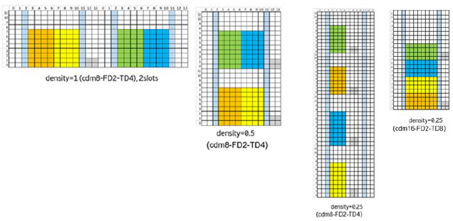
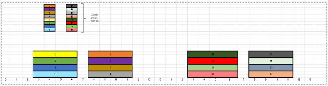
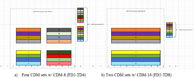
< R1-2603525 : Figure 2. Example of 128-AP single resource CSI-RS configuration, d=1, w/ 4 CDM sets w/ 4 CDM-8 (FD2-TD4) groups in each set. >
< R1-2603525 : Figure 3. Two examples of 128-AP single resource CSI-RS configuration, d=1/2>
< R1-2603525 : Figure 4. Example of 128-AP single resource CSI-RS configuration, d=1/4, w/ 4 CDM sets w/ 4 CDM-8 (FD2-TD4) groups in each set.>
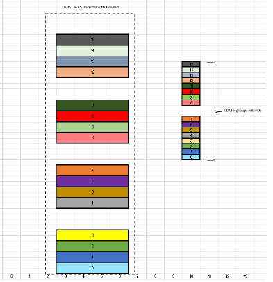
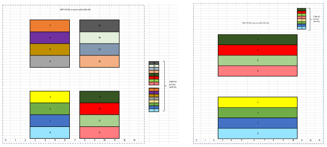
< R1-2603525 : Figure 5. Example of 256-AP single resource CSI-RS configuration, d=1, w/ 4 CDM sets w/ 4 CDM groups in each set, CDM-16 (FD4-TD4)>
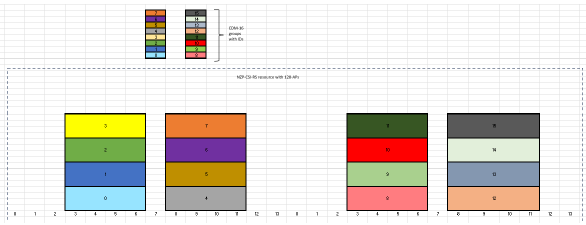
< R1-2603525 : Figure 6. Two examples of 256-AP single resource CSI-RS configuration with d=1/2>
Multiplexing Efficiency and Processing Gains
Increasing the CDM size allows a greater number of antenna ports to be orthogonally multiplexed within a limited number of Resource Elements (REs). This structural enhancement provides two primary benefits:
- Enhanced Coverage: Larger CDM groups facilitate higher transmit power boosting levels across the multiplexed ports and yield greater processing gains, which significantly enhances the received SINR and overall channel estimation quality at the cell edge.
- Compact Resource Allocation: By utilizing new CDM-16 structures—such as FD4-TD4 or FD2-TD8 alongside density adaptations (e.g., density = 1 or 1/2)—a massive 256-port CSI-RS can be efficiently configured within just one or two consecutive time slots. This compact allocation helps reduce both transmission latency and physical resource overhead.
Enhancing Frequency-Domain OCC for FR3 Bands
A fundamental challenge of increasing the CDM size is that spreading Orthogonal Cover Code (OCC) sequences over a wider time and frequency range can degrade channel estimation accuracy, as long OCC sequences are traditionally sensitive to time and frequency variations in the channel. However, this is mitigated by the specific propagation traits of the higher frequency bands targeted for 6G (e.g., FR3). The channel delay spread in FR3 is expected to be relatively small compared to legacy FR1 and FR2 bands. Because of this reduced delay spread, extending the OCC sequence length in the frequency domain becomes a feasible approach. Consequently, new CDM types featuring extended frequency-domain OCCs (e.g., FD-4 or FD-8) are proposed to successfully accommodate larger CDM sizes (like CDM-16) while effectively managing the impacts of frequency selectivity in FR3 environments.
Mitigation of CSI-RS PAPR and false PMI phenomena
CSI-RS is usually discussed as a measurement signal, but its sequence design can create very practical transmitter and receiver problems. A mapping that looks harmless in a small-port system can produce high PAPR when precoding is applied, and the same lack of port distinction can make a UE lock onto the wrong PMI under strong neighbor-cell interference. The key idea in this section is that a small change in how CSI-RS sequences are separated across ports can remove two different failure modes at once.
The High PAPR Problem with Precoded CSI-RS
Under the legacy 5G NR sequence-to-resource mapping, a high Peak-to-Average Power Ratio (PAPR) occurs when CSI-RS is precoded and more than two CSI-RS antenna ports from different Code Division Multiplexing (CDM) groups are configured within the exact same OFDM symbol. This significant PAPR increase at the tail of the transmitted signal distribution degrades the base station's Power Amplifier (PA) efficiency, degrades signal leakage properties, and complicates antenna virtualization. Ultimately, this issue has restricted the practical deployment of precoded CSI-RS in existing NR networks.
The False PMI Phenomenon at the Cell Edge
A secondary issue is the "false PMI" phenomenon, which is observed when transmitting a large number of non-precoded CSI-RS ports. UE with simple receiver processing at the cell edge experiences severe interference from the CSI-RS of neighboring base stations. As a result of this interference, the UE calculates and reports an incorrect Precoding Matrix Indicator (PMI), which misdirects the network to transmit the downlink signal in erroneous directions that do not align with the UE's actual location.
Root Cause and Per-Port Sequence Mitigation
Both the high PAPR and false PMI phenomena share the same root cause: the legacy NR design uses the exact same CSI-RS sequence for all transmitted ports.
To resolve this, the documents propose implementing per-port sequence differentiation. By allocating port-specific CSI-RS sequences—such as through per-port scrambling modifications or CDM-group-specific sequence generation—both issues can be significantly mitigated or completely eliminated without altering the underlying NR Gold sequence-based design.
Performance Benefits over Alternative Mitigations
- PAPR Mitigation: Applying per-port scrambling fully suppresses the PAPR spike for precoded CSI-RS, keeping it equal to the reference non-precoded levels.
- False PMI Mitigation: Eliminating the neighbor-cell CSI-RS interference strictly improves channel estimation. System-level simulations demonstrate clear throughput improvements across all load levels and metric types (average, peak, and cell-edge throughput).
- Comparison to Rate Matching: Using per-port sequences is proven to be vastly superior to the alternative mitigation strategy of utilizing non-colliding CSI-RS with PDSCH rate matching. The rate-matching approach requires planned CSI-RS resources with a reuse factor of 3, which triples the CSI-RS overhead and can actively degrade peak performance
Flexible CSI-RS resource allocation and resource sharing for MRSS and network energy savings
Massive CSI-RS cannot be treated as a fixed block that is dropped into one narrow part of the slot. It has to coexist with DMRS, TRS, different UE capabilities, multi-RAT operation, and energy-saving modes where only part of the antenna array may be active. The common theme here is flexibility: the same reference-signal framework should allow dense full-array sounding when needed, partial sounding when sufficient, and shared resources when several UE classes must be supported together.
Flexible Resource Allocation to Avoid Collisions
Configuring a massive number of CSI-RS ports (e.g., up to 256) inherently leads to a dense occupation of Resource Elements (REs) within a single slot. This dense occupation creates a critical risk of resource collisions and potential severe interference with other essential reference signals, such as DMRS and Tracking Reference Signals (TRS).
To prevent these collisions, the documents propose relaxing the rigid legacy 5G NR allocation rules, which currently rely on restricted symbol locations and fixed Resource Block (RB)-level allocation patterns. Instead, a more flexible time and frequency resource allocation scheme should be adopted. This adaptable configuration would allow massive CSI-RS patterns to be defined flexibly across single or multiple slots and across multiple RBs, fundamentally distributing the dense resource footprint to coexist seamlessly with other channels.
Hierarchical CDM Designs for Resource Sharing (MRSS)
To further minimize the total CSI-RS overhead, it is proposed that a single massive CSI-RS resource be shared among User Equipment (UEs) with varying measurement capabilities. In this scenario, the base station transmits a massive CSI-RS resource (e.g., 256 ports) for high-capability UEs or AI/ML-based predictors, while a "partial port sounding" feature allows low-capability or legacy UEs to measure only a specific subset of those ports.
However, if the massive CSI-RS uses a large Code Division Multiplexing (CDM) size, low-capability UEs face a fundamental limitation: they cannot process the entire long Orthogonal Cover Code (OCC) sequence. This inability causes a severe loss of orthogonality, resulting in crippling intra-resource interference from the unmeasured ports within the same CDM group.
To resolve this, a hierarchical CDM design is proposed within the single CSI-RS resource. Under this design, the OCC sequences are structurally nested or partitioned. Advanced UEs can process the entire resource using the overarching large CDM sequence (e.g., length-8 OCC) to extract all ports, while low-capability UEs can safely measure a smaller CDM subset (e.g., using length-4 or length-2 OCC) to extract just their required port subset. This prevents OCC interference from the unmeasured ports and natively supports Multi-RAT Dual Connectivity (MRSS) and legacy UE coexistence.
Density Adaptations for Network Energy Savings (NES)
Network Energy Savings (NES) techniques allow the base station to dynamically adjust the number of active antenna ports for transmission depending on actual traffic conditions, which requires evaluating CSI for partial transmit arrays.
Both sparse reference signaling (used for general overhead reduction) and spatial-domain NES techniques require flexible and dynamic configuration mechanisms. These mechanisms allow the network to share CSI-RS resources on the same set of physical resources by adapting the density of the reference signal in both the spatial domain (e.g., transmitting/measuring only subsets of antenna ports) and the frequency domain. Striving for a common port subset handling framework for both NES port muting and general overhead reduction allows networks to effectively reduce energy consumption while maintaining reliable link adaptation
Cell-specific precoded and network-assisted beamformed CSI-RS frameworks
Non-precoded CSI-RS is simple, but it becomes less attractive when a large array must cover users with limited per-port power. Beamformed CSI-RS can recover much of this coverage by focusing energy, yet it also hides part of the antenna-domain channel from the UE and can force the UE to choose from coarse beam directions. This section explains how 6G may keep the coverage benefit of beamformed CSI-RS while giving the UE enough information to make a more precise PMI decision.
The Coverage Challenge and Cell-Specific Precoded CSI-RS
In conventional 5G NR deployments, CSI-RS are typically non-precoded, meaning the base station transmits them isotropically and distributes its total transmit power across all configured antenna ports. As 6G scales up to massive arrays (e.g., 256 ports), this isotropic distribution causes a severe degradation in the Power Spectral Density (PSD) per port, severely limiting reliable CSI measurement accuracy for cell-edge users.
Configuring dedicated, precoded CSI-RS resources for every individual UE to solve this coverage gap is impractical because it creates excessive resource utilization overhead. To resolve this, a cell-specific precoded CSI-RS framework is proposed. By applying beamforming weights to the CSI-RS transmission, the network can combine the transmit power of multiple antennas to compensate for the PSD loss, while still transmitting the signal cell-specifically so that multiple UEs can share and measure the exact same physical resource, simultaneously improving coverage and minimizing overhead.
The Straddling Loss Problem in Beamformed CSI-RS
While beamforming the CSI-RS concentrates power and limits overhead, it introduces a new performance penalty known as "straddling loss". This occurs when a UE's optimal angle of departure does not perfectly align with the exact center of any of the transmitted CSI-RS beams. Because the UE is forced to report a Precoding Matrix Indicator (PMI) corresponding strictly to one of the available beam directions, the slight misalignment degrades performance compared to non-beamformed CSI-RS. Traditionally, networks would fix this by transmitting a denser, overlapping grid of beams, but this approach requires non-orthogonal precoders and defeats the purpose of reducing CSI-RS overhead.
Network-Assisted CSI Acquisition and Codebook Oversampling
To eliminate the straddling loss without increasing beam density, a network-assisted beamformed CSI-RS approach is proposed. Under this framework:
- Explicit Precoder Signaling: The network explicitly signals the exact CSI-RS precoder information (the spatial filtering weights used to form the beams) to the UE.
- Antenna Domain Reconstruction: Using the known precoder, the UE mathematically "undoes" the beamforming applied to the received signal. It converts the estimated beam-domain channel back into a reconstructed antenna-domain channel.
- Finer Granularity via Oversampling: Because the UE can now observe the underlying channel within the spatial range of the transmitted beams, it can evaluate candidate precoders that lie between the actually transmitted CSI-RS beam directions. During its PMI calculation, the UE applies codebook oversampling (e.g., an oversampling factor of 4), enabling it to report a highly precise, oversampled beam direction that perfectly aligns with its location.
System-level evaluations demonstrate that this network-assisted oversampling effectively neutralizes straddling loss, yielding significant average user throughput gains over legacy beamformed CSI-RS.
Port Decoupling Requirement
To implement this in standardization, the 6G framework must decouple Channel Measurement Resource (CMR) ports from CSI/PMI calculation ports
. In legacy non-precoded NR, these are tightly coupled (a one-to-one mapping between the measured port and the physical antenna)
. For a UE to apply standard Type-I or Type-II codebooks to a precoded CSI-RS, the specification must separate the observed precoded beams (CMR ports) from the full logical antenna dimensions required for PMI calculation
CSI Framework and Reporting Mechanisms
After the UE measures the channel, the next question is how the network configures the measurement and how the UE reports the result. A powerful CSI-RS design is not enough if the control-plane structure is too heavy, if reporting is forced onto the wrong timing, or if the report container does not match the amount and urgency of the information. This section looks at CSI as a procedure, focusing on how 6G can make configuration, triggering, and reporting more flexible without losing scheduler control.
Simplification of the CSI resource configuration framework
As CSI-RS, CSI-IM, multi-TRP, and energy-saving configurations become more diverse, the control-plane structure itself can become a source of overhead. If the network needs many reports and many resource assumptions, a deeply nested RRC model makes every configuration heavier than the radio feature it is trying to support. This section focuses on simplifying the framework so that 6G can add richer CSI behavior without carrying an unnecessarily complex signaling structure.
The Legacy 3-Level RRC Structure and Signaling Overhead
In 5G NR, channel measurement and interference measurement resources are configured using parallel 3-level Radio Resource Control (RRC) structures. For channel measurements, a CSI-ReportConfig Information Element (IE) points to a CSI-ResourceConfig, which in turn points to an NZP-CSI-RS-ResourceSet containing individual NZP-CSI-RS-Resource configurations. An independent, parallel 3-level structure is used to configure Interference Measurement (CSI-IM) resources.
This 3-level framework is overly complex and results in very high RRC configuration overhead. Analysis shows that approximately 80% of the ASN.1 signaling is related to configuring this CSI framework. The overhead problem becomes particularly severe when the network needs to configure multiple CSI-ReportConfigs to a UE to receive different types of feedback simultaneously (e.g., configuring separate reports for Type I CSI, eType II CSI, and eType II Coherent Joint Transmission (CJT) for multi-TRP setups).
Proposed 2-Level Simplification
To streamline the framework for 6G and support the addition of multi-TRP nodes more efficiently, transitioning to a 2-level structure is proposed. In the legacy NR framework, the intermediate CSI-ResourceConfig IE only contains a few fields, such as lists of resource sets, Bandwidth Part ID (BWP-Id), and resource type. The proposed simplification eliminates this intermediate level by moving the lists of resource sets directly into the CSI-ReportConfig IE, and moving the BWP-Id and resource type fields directly into the resource set level.
Joint Configuration of NZP-CSI-RS and CSI-IM
Further simplification is proposed by removing the requirement to configure independent resource sets for channel and interference measurements. When a CSI report requires both channel and interference measurements, the framework should allow NZP-CSI-RS and CSI-IM resources to be jointly configured within a single combined resource set, avoiding the redundant parallel structures used in NR.
Addressing Complexities in NES Sub-Configurations
The cumbersome nature of the legacy configuration framework is also a major bottleneck for Network Energy Savings (NES). The Rel-18 NES feature utilizes sub-configurations within the CSI-ReportConfig framework to handle different spatial or power domain adaptation scenarios. Under this design, the UE is required to measure, calculate, and report CSI for each sub-configuration completely separately.
If the network wants to obtain CSI reports for a more diverse set of NES assumptions, the number of required sub-configurations grows. Maintaining multiple independent CSI measurement processes simultaneously imposes a substantial computational burden on the UE, and separately reporting them vastly increases signaling overhead. A streamlined CSI configuration framework is necessary to ensure these demanding NES use cases can be supported without unsustainable inefficiencies.
Decoupling of CSI measurement triggering and CSI reporting to address out-of-order scheduling constraints
In many cases, measuring the channel and sending the report do not need to happen as one tightly coupled action. The UE may need more time to compute CSI than ordinary uplink data needs, and forcing both onto the same scheduling timeline can block otherwise valid transmissions. The main idea here is to separate the moment when the UE starts CSI processing from the moment when the network asks for the completed report, so CSI can be prepared in the background and used when it is actually needed.
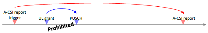
< R1-2604743 : Figure 5-2: OoO scheduling of DCI-to-PUSCH � A-CSI reporting case >
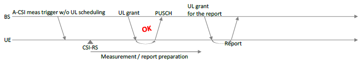
< R1-2604743 : Figure 5-3: Decoupling between A-CSI meas. trigger and PUSCH scheduling for the corresponding A-CSI report >
The Problem in 5G NR: Synchronous Triggering and Out-of-Order Restrictions
In legacy 5G NR, an Aperiodic CSI (A-CSI) report is triggered via a single UL DCI, which synchronously schedules the CSI report alongside potential uplink data on the PUSCH. However, A-CSI computation requires a significantly longer and more relaxed processing timeline compared to standard PUSCH data transmissions.
This creates a major bottleneck due to strict "out-of-order" (OoO) scheduling restrictions mandated in the TS 38.214 specifications. Under these rules, once an A-CSI report is triggered, the network is strictly prohibited from providing any subsequent UL grant to schedule a PUSCH transmission that would occur *beforethe completion of the delayed A-CSI report. Because high-resolution CSI computation timelines (such as Type II CJT) can be extremely long, a substantial amount of intermediate uplink resources become blocked and unavailable to the UE.
Impact on Performance and Latency
The combination of synchronous A-CSI reporting and OoO restrictions severely limits PUSCH and PDSCH scheduling flexibility. This restriction forces increased delays for regular PUSCH scheduling and HARQ-ACK feedback reporting, as the UE is forced to deliver the A-CSI report before other uplink transmissions can clear. Consequently, this degrades peak data rates and notably increases uplink tail latency, particularly for cell-edge users.
The Proposed 6G Solution: Decoupled Triggering
To overcome these scheduling limitations, it is proposed to split the A-CSI reporting process into two decoupled steps, removing the strict time relation between measurement and reporting:
- Step 1 (Measurement Trigger): The base station issues a first trigger (e.g., via a DL DCI) that solely instructs the UE to measure the CSI-RS resource and compute the CSI, without scheduling the corresponding uplink reporting resource.
- Step 2 (Reporting Trigger): After the UE performs the measurement and computation, the base station sends a second, decoupled trigger (e.g., an UL DCI) that provides the UL grant to actually transmit the PUSCH carrying the CSI report.
Benefits of Decoupling
By removing the synchronous scheduling constraint at the moment of the initial trigger, the reporting resource is no longer scheduled well in advance. Therefore, the network is completely free to schedule regular UL-SCH data transmissions during the time the UE is busy computing the CSI. Furthermore, because the UE has already finished computing the CSI by the time the second UL grant arrives, the time gap between receiving the UL grant and transmitting the PUSCH carrying the CSI report can be significantly reduced. Ultimately, this framework alleviates PUSCH scheduling restrictions, avoids unnecessary data transmission delays, and substantially reduces uplink latency.
Signaling container considerations for CSI reporting comparing L1-UCI and L2 MAC CE
CSI reporting is not only about what information the UE sends, but also about where that information is carried. L1-UCI gives tight timing and direct scheduler control, while MAC CE can be more flexible for larger or less time-critical payloads. This section compares those containers from the viewpoint of latency, reliability, resource usage, and how much freedom 6G should give the network when different CSI report types have different urgency.
Signaling Container Options for CSI Reporting: L1-UCI vs. L2 MAC CE
The transition to 6G requires evaluating the optimal signaling medium for CSI reporting. The discussion largely centers on restricting CSI reporting to the PUSCH and choosing between Layer 1 UCI(L1-UCI) and Layer 2 MAC CE (L2 MAC CE).
Arguments Favoring L1-UCI (PUSCH)
Proposals supporting L1-UCI highlight its predictability, efficiency, and lack of cross-layer complexity:
- Controlled Latency and Reliability: L1-based reporting provides a strictly controlled timeline. Its latency remains unchanged when scheduled on PUSCH, whereas MAC CE reporting may suffer from additional MAC processing delays and HARQ retransmission delays if the initial transmission fails. L1-UCI also natively supports varying reliability levels using existing NR mechanisms.
- Efficiency and Fixed Overhead: L1-UCI maintains the same efficiency as legacy 5G NR, where payload size is determined exactly by the CSI content. In contrast, L2 MAC CE requires parsing CSI contents into octets, resulting in additional overhead from MAC sub-headers and potential padding or reserved bits.
- Simpler Cross-Layer Implementation: L1-UCI avoids the cross-layer processing complexity that occurs between L1 and L2 at both the UE and the network.
- Congestion Control: Because L1-UCI reporting instances are fully controlled and scheduled by the network, it avoids the congestion risks associated with asynchronous MAC CE reporting, especially in cells with a large number of UEs.
Arguments Favoring L2 MAC CE
Conversely, proposals advocating for L2 MAC CE argue that the synchronous, tailor-made channels in NR contribute to immense system complexity, which MAC CE naturally resolves.
- Handling Varying and Large Payloads: L2 MAC CE natively supports varying CSI payload sizes without requiring the network to know the exact payload beforehand, making it highly suitable for UE-initiated CSI reporting. For exceptionally large payloads—such as advanced AI/ML-based CSI or Joint Sensing and Communication (ISAC) reports—L2 can seamlessly handle segmentation via the transport protocol. Under L1-UCI, maximum payloads are strictly capped by the limits of Polar codes (e.g., 1706 bits), whereas L2 is limited only by the maximum Transport Block Size (TBS).
- Reduced Multiplexing and Priority Complexity: L2 MAC CE eliminates the need for complicated L1 UCI multiplexing rules, as multiple reports are easily concatenated as MAC CEs. It also removes the need to define strict CSI priority rules, as each report payload is self-contained.
- Flexible Timeline and Asynchronous Reporting: Utilizing L2 removes the need to standardize rigid, pessimistic, worst-case CSI processing timelines, allowing the UE to report CSI asynchronously whenever processing finishes.
- Simplified Cross-Carrier Operation: L2 reporting drastically simplifies sending CSI for higher-frequency downlinks (e.g., FR2) via lower-frequency uplinks (e.g., FR1) without painful UCI multiplexing rules, easily supporting carrier aggregation with non-ideal transport delays.
- Rebuttal to Overhead and Latency Concerns: Proponents of L2 argue that the overhead from MAC sub-headers is negligible (e.g., 1.7% to 3.7% efficiency loss) when the CSI is piggybacked onto a typical PUSCH data transmission, such as a TCP-ACK. Furthermore, the added MAC processing latency (roughly 1ms) and potential HARQ retransmission delays result in negligible downlink throughput degradation (less than 2%).
Introduction of UE-initiated and event-triggered CSI reporting
Periodic CSI reporting is easy to manage, but it can waste resources when the channel is stable and can still be too slow when the channel changes suddenly. UE-initiated and event-triggered reporting changes the viewpoint: the UE reports when it detects that the old CSI is no longer useful or when a meaningful channel event has occurred. The challenge is to get this responsiveness without letting the UE and network drift into different assumptions about what should be reported and when.
The Concept of UE-Initiated and Event-Triggered CSI Reporting
In legacy 5G NR systems, CSI is typically reported in a periodic manner with a fixed rate. However, radio channels can vary rapidly for some users due to mobility or interference, while remaining relatively stable for others. Under fixed periodic reporting, the network receives excessive, redundant CSI reports when the channel is stable, which wastes uplink physical resources and drains the UE battery. Field data analysis indicates that up to 41% of periodic CSI reports can be entirely redundant because the channel does not change significantly between reporting intervals.
To address this inefficiency, UE-initiated (or event-triggered) CSI reporting is proposed. Under this framework, the UE monitors the channel autonomously and ties the transmission of a CSI report—or the selection of a new CSI reporting configuration—to specific channel conditions rather than a fixed time pattern.
Triggers and Event Conditions
The events that trigger a CSI report can be based on several metrics:
- CSI Quantities: Variations in metrics such as CQI, Rank Indicator (RI), or Precoding Matrix Indicator (PMI). For example, the UE may trigger a report only when it detects a sufficient variation between the currently calculated PMI (or the wideband part of the PMI) and the last reported PMI.
- Channel Property Metrics: Threshold crossings related to Time, Frequency, or Spatial Domain Channel Properties (TDCP, FDCP, SDCP).
- Network Instructions: Non-measurement events, such as the activation of a Secondary Cell (SCell).
Performance Benefits: Overhead Reduction
System-level simulations demonstrate that event-triggered CSI reporting provides significant efficiency gains. In urban macro scenarios, tying CSI reporting to variations in the PMI successfully reduced the uplink CSI feedback overhead by roughly 40%. Despite this massive reduction in feedback, the mean User Perceived Throughput (UPT) was maintained within approximately 2% of the legacy periodic CSI baseline across various network load levels. This confirms that event-triggered mechanisms can successfully suppress unnecessary reports while still reacting fast enough to channel variations to preserve link adaptation performance.
Debates and Concerns: Complexity and Network Misalignment
Despite the demonstrated overhead reductions, the necessity and feasibility of implementing UE-initiated CSI reporting are heavily debated due to several technical challenges:
- PMI Event Definition Challenges: While it is relatively straightforward to trigger reports based on beam quality or CQI/RI changes, extending this to the PMI is highly complex. The PMI relies on instantaneous channel states and is quantized by indices mapping to specific codebook matrices, making it technically difficult to define a stable, proper event trigger for PMI variations.
- Misalignment with Network Logic: Allowing the UE to autonomously decide when to report CSI may not always align with the base station's overarching scheduling, interference management, and resource allocation strategies.
- Increased UE Burden: Shifting the trigger decision to the UE requires the device to continuously maintain local channel estimation and evaluate complex trigger logic. This requirement fundamentally increases the UE's computational complexity and power consumption, potentially offsetting the battery savings gained from transmitting fewer uplink reports.
Asynchronous CSI reporting and dynamic parameter updating
CSI becomes less useful as it ages, and this aging problem becomes worse when the report must wait for a rigid uplink opportunity or when key reporting parameters can only be changed through slow RRC signaling. Asynchronous reporting and dynamic parameter updates try to make CSI handling more elastic. The goal is to let the UE send useful CSI closer to the time it is computed and let the network adjust important reporting assumptions without rebuilding the whole configuration.
The Problem with Legacy Synchronous CSI Timelines (Forced Aging)
In 5G NR, CSI triggering operates synchronously, meaning the network must provision a reporting offset that strictly adheres to fixed CSI computation timelines (defined as Z and Z' values) hardcoded in the specifications. These rigid timelines were established based on the expected worst-case processing capabilities of UEs. Consequently, even if a highly capable UE finishes computing the CSI early—or lacks parallel processing tasks—it is forced to wait until the defined worst-case timeline expires before it can report the data. This creates an inherent and artificial "CSI aging" component, degrading MIMO performance by forcing the network to rely on delayed channel state information. Furthermore, these legacy timelines have expanded arbitrarily across releases (e.g., a 128-port Type I CSI may require 288 symbols, while a more complex Type II CJT CSI requires only 141 symbols), leading to severe scheduling challenges and capability fragmentation.
The Proposed Solution: Asynchronous CSI Reporting
To resolve this bottleneck in 6G, replacing these rigidly standardized, pessimistic timelines with an asynchronous reporting framework is proposed. Instead of a fixed point in time, the network would define an asynchronous time window. The UE can process the CSI at its own pace and report it dynamically whenever the computation finishes, taking advantage of the next available uplink transmission opportunity (such as an upcoming PUSCH grant) within that window.
Benefits of Asynchronous Reporting
- Reduced CSI Latency: Rather than a fixed worst-case delay, the CSI reporting delay becomes a statistical time distribution, allowing capable UEs to report much earlier than legacy timelines would permit.
- Future-Proofing Chipset Evolution: It removes the need for standardized worst-case specifications, allowing future, faster chipset generations to inherently reduce CSI latency without requiring specification updates.
- Efficient Resource Utilization: Because the UE can report whenever ready, the report can easily piggyback on existing PUSCH transmissions (e.g., those carrying TCP-ACKs), which are highly common, bypassing the need for the network to use dedicated control channels just to schedule the CSI report.
The Problem with Static RRC Parameter Configurations
In current networks, CSI report parameters are configured semi-statically via RRC signaling. Because RRC reconfigurations are slow and costly, they cannot adapt to short- or mid-term channel variations. To bypass this limitation, networks are currently forced to configure a UE with multiple, separate static CSI report configurations corresponding to different parameter combinations (e.g., four different parameter sets for an eType-II codebook). The network must then experiment by triggering these different reports to identify the optimal parameter combination, which generates excessive signaling overhead and forces the UE to juggle measurements and computations across multiple configurations.
Dynamic Parameter Updating
To streamline this process, 6G proposes supporting dynamic parameter updating. Instead of configuring multiple static reports, the network configures only a single CSI report. The specific parameter combinations within that report can then be dynamically updated by the network on the fly, guided by channel property information received from the UE (such as Spatial Domain Channel Property, or SDCP, feedback). This fully avoids the RRC signaling overhead of maintaining multiple configurations, makes tracking the active report simpler for the network, and significantly reduces the UE's computational burden, as the UE only needs to measure and compute for a single parameter combination at any given time.
Decoupled RI and PMI/CQI computation and reporting
Rank, precoder, and CQI are related, but they do not always need the same update rate or the same measurement window. Rank often changes more slowly, while PMI and CQI may need to follow faster channel and interference variations. By decoupling these parts of CSI, 6G can reduce unnecessary reporting and computation, but it must also manage the risk that one part of the report becomes inconsistent with the others.
Decoupled RI and PMI/CQI Computation and Reporting
- The Problem of PMI Search Complexity : In 5G NR, CSI reports were expanded to support up to 128 ports, and 6G is expected to push this limit even higher to 256 ports. This massive number of ports drastically increases the number of candidate precoders, which raises the PMI search complexity at the UE to potentially unbearable levels. If the complexity is too high, the UE may be forced to perform sub-optimal PMI searches, ultimately degrading network performance.
- The Different Time-Scales of RI and PMI/CQI : The RI captures the preferred transmission rank, which typically remains stable over relatively long time intervals. In contrast, the CQI and PMI capture instantaneous channel quality and spatial structure, which fluctuate rapidly and require much more frequent updates.
- Issues with Coupled Reporting :When RI computation and reporting are strictly tied to the CSI-RS periodicity (and thus coupled directly with PMI/CQI), it creates inefficiencies. If the CSI-RS periodicity is short, the UE wastes processing power and battery life computing and reporting the RI more often than necessary. Conversely, if the periodicity is long, the RI updates may become too infrequent to properly align with the actual rank dynamics of the channel.
- Benefits of Decoupling : To resolve this, it is proposed to decouple the computation and reporting of RI from PMI/CQI:
- For the UE (Skipping Hypothesis Testing): The UE can report RI at a much larger periodicity (e.g., 2 to 5 times the PMI/CQI periodicity). For the frequent PMI/CQI reports in between, the UE simply conditions its calculations on the latest reported RI (or a specific RI requested by the network). This completely removes the need for the UE to perform exhaustive rank hypothesis testing during those intermediate PMI searches, saving significant computation and energy.
- For the Network (Simplified Decoding): Because the RI is not dynamically changing in every PMI/CQI report, the payload variation of those reports is significantly smaller. This simplifies network-side decoding by avoiding the complex "two-part decoding" typically required for highly variable CSI payloads.
- Performance Impact: System-level simulations in an Urban Macro (UMa) scenario at 4 GHz demonstrate that decoupling RI computation and reporting with an appropriate periodicity results in a very small performance difference (e.g., 2-5% throughput loss) compared to conventional joint reporting, proving it is a highly efficient trade-off.
Alternative CSI Acquisition and Feedback Strategies
- DMRS-based CSI acquisition and feedback for PDSCH and PDCCH
- PDSCH DMRS: Legacy NR relies on sparse CSI-RS transmissions (e.g., 20ms periodicity) for link adaptation, which is often too slow to track real-time channel conditions for bursty traffic, resulting in conservative and inaccurate MCS selections. Utilizing PDSCH DMRS allows the UE to assess the actual link quality of an ongoing data transmission and provide real-time CQI updates. This tracks CQI variations between the sparse CSI-RS occasions, improving average throughput by up to 11% while removing the need for dense periodic CSI-RS.
- PDCCH DMRS: Link adaptation for the PDCCH is traditionally performed by applying a fixed back-off (e.g., 3 dB) to the PDSCH SINR. However, the control region experiences drastically different interference and loading than the data region—especially in uplink-heavy traffic where the control region is congested but the data region is sparse. Using PDCCH DMRS to compute and report CSI (such as L1-SINR) specifically for the control region significantly improves PDCCH link adaptation, keeping CCE usage efficient and preventing massive success rate drops under high traffic loads.
- Early CSI acquisition for mobility and state transitions
- When a UE transitions from IDLE/INACTIVE to CONNECTED, activates a Secondary Cell (SCell), or undergoes a cell switch, the network initially lacks prior channel knowledge. Consequently, the network is forced to rely on fallback transmission schemes with conservative MCS and no closed-loop precoding, degrading initial throughput.
- To mitigate this, early CSI acquisition mechanisms trigger reference signal measurement and reporting before or during the transition. This can be achieved by mandating simple early CQI reporting based on DMRS via Msg3 during initial access without requiring UE capability indication. Additionally, AI/ML-based temporal prediction can be utilized to predict and report the future CSI of a target cell before a cell switch actually occurs, allowing the network to apply optimal precoding immediately upon transition.
- UE-assisted Channel Property Information (TDCP, FDCP, SDCP) and IPN feedback
- Channel Property Information (CPI): Instead of just instantaneous CSI, the UE can report long-term channel statistics.
- Time Domain (TDCP):Tracks temporal correlation to help the network choose between low-overhead Type I or delay-sensitive Type II codebooks.
- Frequency Domain (FDCP):Tracks inter-subband correlation to optimize the frequency density of CSI-RS or subband reporting sizes, achieving ~60% overhead reduction with only minor throughput loss.
- Spatial Domain (SDCP):Tracks long-term spatial covariance and dominant beam indices. This assists the network in configuring precoded CSI-RS, determining the number of DFT beams, or performing interference-aware coordinated scheduling across multiple Transmission Reception Points (TRPs), which has shown to provide a 26% throughput gain.
- Interference Plus Noise (IPN) Feedback: In reciprocity-based TDD networks, the base station acquires the downlink channel via uplink SRS, but it still lacks accurate UE-side interference information required for proper MCS and rank selection. Legacy NR workarounds (like configuring a redundant Type I PMI/CQI report or relying on non-PMI reports) suffer from high overhead, excessive delay, and precoder mismatch. Introducing a standalone subband IPN report provides the exact scalar interference information needed, significantly improving reciprocity-based downlink transmissions and enabling highly accurate frequency-selective scheduling.
Alternative CSI Acquisition and Feedback Strategies
Not every useful CSI value has to come from a conventional CSI-RS report. Some information can be inferred from DMRS, some can be obtained early during mobility or state transitions, and some can be reported as channel properties rather than as a full channel estimate. This section collects these alternatives because they all address the same practical issue: the network often needs fresher or more targeted channel knowledge than a normal CSI-RS cycle can provide.
DMRS-based CSI acquisition and feedback for PDSCH and PDCCH
CSI-RS gives planned channel measurements, but it may not always reflect the exact channel condition seen by the scheduled data or control transmission. DMRS is already embedded in PDSCH and PDCCH, so it can provide a more immediate view of the link that the UE actually experienced. This section considers DMRS-based feedback as a way to refine link adaptation with fresh scalar information, especially when CSI-RS density is limited or the channel changes quickly.
The Limitation of Legacy Sparse CSI-RS
In 5G NR, link adaptation relies on periodic CSI-RS and CSI-IM resources to evaluate the downlink channel. In practical deployments, these reference signals are often configured sparsely in time, such as with a 20 ms periodicity, to avoid consuming excessive downlink resources. However, this sparse transmission creates a slow control loop that struggles to track real-time channel fluctuations, especially for short, bursty traffic. Consequently, the network is often forced to make conservative and inaccurate MCS selections. While increasing the transmission frequency of CSI-RS would solve this, it would drastically increase signaling overhead, increase interference, and reduce the physical resources available for actual data transmission.
PDSCH DMRS for Real-Time Rate Adaptation
To bridge the gap between sparse CSI-RS occasions without increasing overhead, 6G proposes leveraging the DMRS inherently associated with PDSCH transmissions. Because DMRS is already transmitted alongside downlink data for basic demodulation, using it for intermediate channel estimation requires zero additional radio resource allocation.
By assessing the actual link quality of an ongoing PDSCH transmission via DMRS, the UE can provide real-time, intermediate CQI updates to the network. This gives the scheduler true, real-time insight into how close the current link adaptation is to the desired target, significantly improving MCS selection for bursty traffic. System-level evaluations demonstrate that complementing baseline CSI-RS with PDSCH DMRS-based CQI updates provides consistent gains of up to 11% in average user throughput and up to 14% in 5-percentile (cell-edge) throughput.
Focus on Scalar Metrics (CQI/L1-SINR)
Because DMRS configurations (such as port mapping and density) are dynamically scheduled and can vary drastically from one PDSCH transmission to another, DMRS lacks the stable spatial resolution and diversity of dedicated CSI-RS. Therefore, DMRS-based CSI acquisition should focus strictly on scalar, CQI-like metrics (such as CQI or L1-SINR) that provide a direct measure of overall channel quality, rather than spatial metrics like Rank Indicator (RI) or Precoding Matrix Indicator (PMI), which cannot be reliably estimated using DMRS alone.
PDCCH DMRS for Control Region Link Adaptation
Link adaptation for the PDCCH such as choosing the correct aggregation level is traditionally performed using measurements taken from the data region (e.g., CSI-RS) by applying a fixed back-off (e.g., 3 dB) to the estimated PDSCH SINR.
However, the interference and loading conditions in the control region often differ drastically from those in the data region. For example, when a network serves many UEs with small data packets or during uplink-heavy traffic, the data region remains sparsely loaded while the control region becomes highly congested. In these scenarios, relying on data-region CSI-RS leads to sub-optimal, statistically skewed PDCCH link adaptation. By utilizing PDCCH DMRS to measure and report a CSI quantity (like L1-SINR) specifically for the control region, the network can accurately track this unique interference loading. Simulations show that this dedicated PDCCH feedback achieves more efficient Control Channel Element (CCE) usage at medium loads and prevents massive drops in the PDCCH success rate (BLER) under high traffic loads.
Early CSI acquisition for mobility and state transitions
When a UE moves between cells or returns from a low-activity state, the network often needs channel knowledge before the normal CSI process has caught up. Without early CSI, the scheduler may fall back to conservative settings, which protects reliability but costs throughput and delay. The purpose of this section is to show how 6G can obtain usable CSI earlier, either through procedure-linked reporting or prediction, so the first transmissions after a transition are not blind.
The Challenge: Fallback Degradation During Transitions
When a UE undergoes state transitions—such as moving from RRC_IDLE/RRC_INACTIVE to RRC_CONNECTED, transitioning a Secondary Cell (SCell) from a deactivated or dormant state to an active state, or performing a cell switch—the network initially lacks accurate prior channel knowledge. Because it does not know the optimal transmission parameters, the network is forced to rely on fallback transmission schemes immediately after the transition. This typically involves using highly conservative MCS selections and transmitting without closed-loop precoding (which is especially detrimental for large massive MIMO antenna arrays), resulting in severely degraded throughput during the initial transmission phase.
Mandatory Early CQI Reporting via Msg3
To mitigate this degradation and enable the network to apply closed-loop precoding and higher MCS immediately upon connection setup, early CSI acquisition mechanisms are required. However, specifying multiple optional early CSI features may lead to low adoption in real deployments due to UE capability fragmentation.
To guarantee that early CSI is widely utilized in 6G, it is proposed to establish a minimum set of early CSI features that are mandatory for all 6G UEs to support. A primary candidate for this is simple, early CQI reporting based on DMRS or other available reference signals. Because early CQI calculation requires low computational complexity for the UE, it can be made mandatory without requiring any UE capability indication signaling. Under this framework, the UE could automatically compute and include this early CQI report directly within Msg3 during the initial access (RACH) procedure, providing the network with immediate channel insight.
AI/ML-Based Temporal Prediction for Cell Switching
For mobility scenarios (such as L1/L2-triggered mobility or L3 handovers), AI/ML-based temporal-domain CSI prediction offers an advanced mechanism for early CSI acquisition. Instead of waiting to measure the target cell after switching, the UE can utilize AI/ML predictors to forecast the future CSI of candidate cells before the cell switch actually occurs.
Specifically, predicting and reporting the future CQI or Interference Plus Noise (SINR) of candidate cells prior to the transition provides two major benefits:
- Target Cell Selection: It assists the network in evaluating and deciding which candidate cell is the optimal target for the mobility procedure.
- Immediate Link Adaptation: It enables the target cell to apply optimal link adaptation instantaneously after the switch.
Initial evaluations demonstrate that AI/ML-based temporal-domain predictors for cross-cell early CSI acquisition are highly accurate, achieving SINR prediction errors of only 0.5 to 0.6 dB.
Dependency on Transition Procedures
While recognized as a crucial feature, initiating the detailed design of 6G early CSI acquisition is currently challenging because the fundamental 6G procedural frameworks for Initial Access, RACH, and mobility have not yet been fully defined. Consequently, early CSI acquisition will be treated as a key use-case category that must be integrated once those general transition procedures are established.
UE-assisted Channel Property Information (TDCP, FDCP, SDCP) and Interference Plus Noise (IPN) feedback
The network does not always need a full channel report to make a better scheduling or CSI configuration decision. Sometimes it only needs to know how fast the channel varies in time, how selective it is in frequency, how concentrated it is in space, or how interference changes across subbands. UE-assisted property feedback gives the network this higher-level view, allowing it to tune reference-signal density, reporting granularity, and interference handling without asking the UE to send a complete channel description every time.
UE-Assisted Channel Property Information (TDCP, FDCP, SDCP)
- Concept of Channel Property Information (CPI): Instead of only providing instantaneous channel state feedback tightly coupled to a specific data transmission, the UE can report long-term channel statistics and properties, collectively termed Channel Property Information (CPI). These metrics assist the network in optimizing reference signal densities, codebook parameters, and coordinated scheduling.
- Time Domain Channel Properties (TDCP): Originally introduced in 5G NR Rel-18 based on periodic Tracking Reference Signals (TRS), TDCP captures the temporal variability of the channel. The network utilizes this information to adapt DMRS configurations, switch between SU-MIMO and MU-MIMO operations, and decide whether to configure low-overhead (Type I) or delay-sensitive, high-resolution (Type II) CSI reporting. Additionally, TDCP can assist in time-domain CSI prediction by tracking the cyclic variation of channel prediction quality, allowing the network to target prediction occasions when the accuracy is highest.
- Frequency Domain Channel Properties (FDCP): FDCP captures the degree of frequency selectivity or inter-subband correlation across the reporting bandwidth. The network leverages FDCP to configure the optimal frequency density of CSI-RS resources, PRB bundling sizes, subband reporting sizes, or the compression ratio of frequency domain basis vectors in eType II codebooks. System-level evaluations demonstrate that utilizing FDCP reporting can reduce CSI feedback overhead by approximately 60% with only a minor average throughput loss of roughly 4%.
- Spatial Domain Channel Properties (SDCP): SDCP captures long-term spatial correlation characteristics, helping the network determine Line-of-Sight (LOS) versus Non-LOS conditions, angular spread, and the appropriate number of DFT beams to configure for CSI feedback. SDCP enables two major advanced operations:
- Interference-Aware Coordinated Scheduling: A UE can measure signals from non-serving (interfering) Transmission Reception Points (TRPs) and generate SDCP reports containing the strongest interfering directions and their associated power levels. The serving TRP uses this SDCP information to update its precoder, steering spatial nulls toward the reported interfering directions of UEs served by other TRPs. This approach has demonstrated a 26% average throughput gain in multi-TRP scenarios.
- Long-Term Covariance Reporting: The UE can report its long-term spatial covariance matrix (second-order channel statistics) via SDCP, potentially utilizing compressed transform-domain representations, such as beamspace projection. With this long-term prior, the network can configure cell-specific precoded CSI-RS resources shared among multiple UEs, bypassing the need for UE-specific CSI-RS transmissions. This achieves a CSI-RS overhead reduction of approximately 50% with a negligible throughput difference of about 1%.
Standalone Interference Plus Noise (IPN) Subband Report
- The Problem in Reciprocity-Based Downlink: In Time Division Duplex (TDD) networks leveraging channel reciprocity, the base station effectively acquires the downlink channel estimate by measuring uplink SRS. However, the network still lacks reliable and accurate knowledge of the interference conditions experienced at the UE receiver, which is strictly required to perform optimal Rank and MCS selection.
- Limitations of Legacy Approaches: To obtain this interference data, legacy 5G NR networks must rely on inefficient workarounds. The network can configure a redundant Type I PMI/CQI report, but this introduces unnecessary overhead and suffers from a mismatch because the reported CQI is based on the reported PMI rather than the SRS-derived precoder. Alternatively, the network can rely on non-PMI reporting using UE-specific beamformed CSI-RS, but this procedure is impractical due to high complexity and excessive CSI acquisition delays.
- The Subband IPN Solution: To resolve this, a standalone IPN report with subband granularity is proposed. By directly providing scalar interference information, the IPN report facilitates highly accurate reciprocity-based downlink transmissions and enables frequency-selective scheduling, allowing the network to avoid allocating bad subbands to a UE. Simulations show that the IPN-based approach achieves up to a 19.5% average throughput gain over legacy CQI adjustment methods, whereas the legacy non-PMI approach suffers severe degradation due to latency.
AI/ML, Prediction, and Compression
AI/ML enters the CSI discussion mainly because 6G channel information can become too large, too frequent, or too slow to collect by direct measurement alone. Prediction tries to fill in missing CSI across space, frequency, or time, while compression tries to send the most useful part of the channel with fewer uplink resources. This section separates the promise from the practical constraints by looking at reconstruction accuracy, acquisition delay, UE complexity, and how much coordination is needed between UE and network vendors.
AI/ML and non-AI-based spatial, frequency, and time-domain CSI prediction
Prediction is one of the main ways to reduce CSI overhead, but it is useful only if the missing CSI can be estimated accurately enough for scheduling and precoding. AI/ML methods can learn complex spatial, frequency, or time-domain relationships, while non-AI methods may be simpler and easier to specify. This section compares these directions around the same practical question: when the network sends less reference information today, can the UE or network still infer the channel state needed for tomorrow's transmission decision?
The Concept of CSI Prediction for Overhead Reduction
As 6G networks scale to massive antenna arrays (e.g., 128 or 256 ports), transmitting CSI-RS across all ports continuously generates excessive physical resource overhead. To mitigate this, networks can transmit "sparse" CSI-RS by sounding only a subset of the antenna ports (spatial domain reduction) or a subset of subcarriers/resource blocks (frequency domain reduction). To recover the missing data, the UE utilizes spatial and frequency-domain CSI prediction algorithms to accurately restore the full-dimensional channel estimates from these partially sounded measurements.
Transformer-Based UE-Sided AI Predictors
For AI-based spatial and frequency CSI prediction, the UE deploys an AI/ML model—typically based on a Transformer architecture - that takes the sparse, noisy CSI-RS samples as input and acts as a non-linear interpolator, extrapolator, and denoiser.
- Performance Gains: Evaluations show that Transformer-based AI predictors achieve significant Mean Squared Error (MSE) reductions compared to traditional linear interpolation baselines based on Least Squares (LS) estimation. The AI model improves MSE by approximately 3 dB and outperforms classical baselines even when the CSI-RS density is halved or reduced to just 1/4 of the total ports.
- System-Level Impact: In terms of Spatial Generalized Cosine Similarity (SGCS), AI/ML predictors achieve a highly accurate SGCS of approximately 0.9 even when only 1/4 of the antenna ports are measured. Conversely, applying simple linear interpolation without AI severely degrades user perceived throughput, making it an unviable approach for highly sparse grids.
Non-AI Based Prediction Alternatives
While AI/ML shows superior performance, non-AI-based prediction techniques are also studied as reliable, lower-complexity alternatives that do not require advanced neural network processing. Because simple linear interpolation performs poorly, advanced non-AI methods utilize Linear Minimum Mean Square Error (LMMSE) estimation to exploit spatial and frequency correlation structures. For example, the network can transmit an infrequent full-port CSI-RS to allow the UE to calculate a long-term wideband spatial covariance matrix. The UE then uses this matrix alongside LMMSE to accurately predict and interpolate the missing ports during the frequent, sparse CSI-RS transmissions.
Time-Domain AI Prediction for Mobility and Early CSI
Time-domain CSI prediction focuses on forecasting future channel states to overcome scheduling delays and minimize throughput degradation during mobility procedures, such as cell switching.
- Cross-Cell SINR Prediction: For early CSI acquisition, the UE can utilize AI/ML temporal predictors to evaluate and predict the future SINR or CQI of candidate target cells prior to a handover.
- Accuracy vs. Baselines: AI/ML-based cross-cell prediction demonstrates high accuracy, achieving an average SINR prediction error of only 0.5 to 0.6 dB. This vastly outperforms the traditional Sample-and-Hold (SaH) baseline, whose prediction error increases rapidly over time. By predicting the target cell's channel accurately, the network can apply optimal closed-loop link adaptation immediately upon cell switching.
- Model Fine-Tuning: Because propagation environments change randomly, relying solely on static offline training can degrade prediction performance. To address this, online fine-tuning is evaluated as a Life Cycle Management (LCM) procedure, allowing the UE to fast-adapt its local time-domain AI model to the specific, real-time channel measurements using few-shot learning techniques.
CSI-RS overhead reduction strategies for massive antenna arrays
For very large arrays, always sounding every port and every useful frequency location can consume too much of the downlink resource grid. Sparse CSI-RS is therefore attractive, but sparse measurement is only helpful if the missing channel can be reconstructed before the scheduling decision loses its value. This section highlights the important difference between reconstruction accuracy in an ideal sense and the actual user throughput after waiting time, traffic burstiness, and periodic full-port measurements are included.
The CSI-RS Overhead Challenge
As 6G networks scale to massive antenna arrays (e.g., up to 256 ports), transmitting CSI-RS on all active antenna ports continuously results in massive physical resource overhead, leaving very few time-frequency resources available for actual data transmission. To mitigate this, networks can employ sparse CSI-RS transmission strategies.
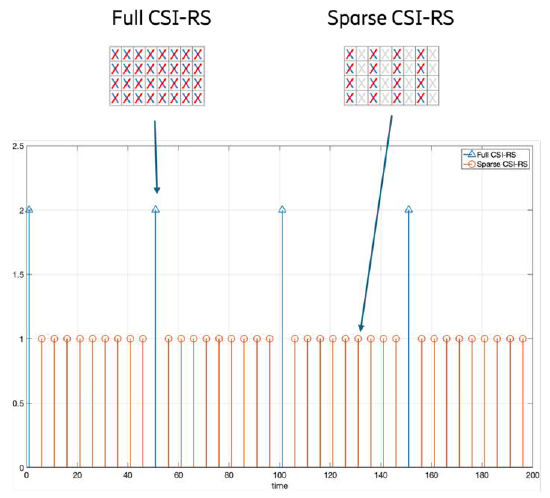
< R-2604533 : Figure 8: Combining full and sparse CSI-RS transmissions to reduce CSI-RS overhead >
Spatial and Frequency Domain Sparsity
- Spatial Domain Reduction: The network transmits CSI-RS only on an active subset of the antenna array, effectively muting the remaining ports (e.g., sounding only half or a quarter of the total ports).
- Frequency Domain Reduction: The network transmits CSI-RS on only a subset of frequency resources, such as alternating PRBs or subcarriers. Densities can be reduced to 1/2, 1/4, or even down to 1/8 RE/RB/port.
Non-AI/ML Approaches for Channel Reconstruction
When CSI-RS is transmitted sparsely, the UE must reconstruct the missing channel information for the unmeasured ports. Two primary non-AI techniques are evaluated:
- Linear Interpolation: The UE applies simple linear interpolation, where the channel of an unmeasured port is estimated using the nearest measured ports based on CSI-RS port indexing. Alternatively, the UE can simply set the channel estimate to zero for the missing ports. However, system-level simulations reveal that standard linear interpolation performs very poorly on highly sparse, vectorized antenna grids, resulting in extremely low throughput.
- Combining Partial and Full-Port Transmissions: To recover the spatial resolution lost by port muting, networks can combine frequent sparse CSI-RS transmissions (e.g., with a 10ms periodicity) with infrequent full-port CSI-RS transmissions (e.g., with a 50ms periodicity). The UE utilizes the infrequent full-port transmission to estimate the wideband spatial covariance between every CSI-RS port pair. The UE then uses this estimated spatial covariance to apply Linear Minimum Mean Square Error (LMMSE)-based interpolation to accurately reconstruct the channel for the muted ports during the frequent sparse transmissions.
The Trade-off: User Throughput vs. Acquisition Delays
While the combined partial and full-port sounding method achieves very high actual channel reconstruction accuracy, it suffers from a severe CSI acquisition delay.
If a UE arrives and receives a partial-port CSI-RS first, it must wait for the next periodic full-port transmission to obtain the spatial covariance matrix required to predict the full-port CSI. This waiting period introduces a significant delay before the start of the downlink transmission, which is particularly detrimental for bursty traffic (such as FTP1 models) where a UE may only have a single packet to transmit.
Because of this delay, the actual User Perceived Throughput (UPT) severely degrades. When accounting for these scheduling and acquisition delays, the overall throughput performance of the combined scheme drops to levels similar to a baseline where all ports are transmitted continuously, effectively nullifying the benefits of the highly accurate LMMSE channel reconstruction.
AI/ML-based CSI compression utilizing JSCM (Joint Source, Channel Coding, and Modulation) and downloadable codebooks
CSI feedback can become too large when the channel dimension grows, so 6G has to look beyond simply adding more report bits. One direction is to learn a compact representation that survives the uplink channel itself, and another is to let the network download a better basis so the UE can search a smaller and more relevant codebook. The common purpose is to preserve useful channel information while reducing UE complexity, feedback overhead, and the amount of cross-vendor AI coordination required.
The JSCM Framework and Cliff Effect Mitigation
Traditional 5G NR networks utilize Separated Source and Channel Coding (SSCC), which involves a sequential chain of compression, quantization, coding, and modulation. Joint Source, Channel Coding, and Modulation (JSCM) replaces this chain by treating CSI feedback as a single learned transmit-receive mapping. Under JSCM, the UE compresses the target CSI directly into a low-dimensional latent vector of modulated symbols, which are then mapped directly to the uplink physical resource blocks.
System evaluations demonstrate that by jointly optimizing the source and channel processing, JSCM improves feedback reliability and alleviates the "cliff effect"—a phenomenon where classical SSCC schemes experience a rapid performance drop when the actual channel SNR falls below the configured rate adaptation. Consequently, JSCM significantly outperforms legacy schemes in the low-SNR region. To ensure these directly mapped symbols meet practical RF transmitter requirements (such as Peak-to-Average Power Ratio, or PAPR), the JSCM symbols can be constrained or quantized to discrete standard NR constellations (e.g., 16-QAM to 1024-QAM) during training, which incurs only a minor performance loss.
Kronecker-Based Learnable Projection Matrix
JSCM can be implemented using a linear projection matrix at the UE, which is a lower-complexity alternative to deploying a full neural network encoder. However, a standard fully learnable linear projection matrix requires an immense number of parameters (e.g., 119,808 parameters for a configuration of 32 ports, 13 subbands, and 72 allocated Resource Elements).
To drastically reduce this parameter footprint, a Kronecker-based model is proposed, which replaces the large original matrix with the Kronecker product of two smaller matrices.
- Parameter Reduction: By sharing learnable parameters between the real and imaginary parts of the complex-valued CSI, a fully learnable Kronecker model reduces the parameter count to just 462, while incurring a negligible Spatial Generalized Cosine Similarity (SGCS) performance drop of approximately 0.02 compared to the massive 119,808-parameter matrix.
- Further Simplification: Employing a partially learnable model (where one matrix is learned and the other is fixed) reduces the count to just 78 parameters.
- Quantization: Because these parameters must be downloaded from the network to the UE, they can be further compressed using 4-bit or 8-bit scalar quantization, maintaining performance that consistently outperforms fixed baselines.
Downloadable Codebooks and Bypassing Inter-Vendor Collaboration
Deploying full two-sided AI/ML models (an encoder at the UE and a decoder at the network) introduces severe inter-vendor collaboration complexities regarding model training, performance monitoring, and RAN4 conformance testing.
To bypass these complexities, the "downloadable codebook" framework is proposed as a prioritized, one-sided solution. Under this framework, the network utilizes cell, site, or UE-specific channel characteristics to learn an optimized Spatial Domain (SD) and/or Frequency Domain (FD) basis. The network then downloads these optimized bases to the UE.
Simplifying the UE's PMI Search
Once the UE receives the downloaded basis, it computes the Precoding Matrix Indicator (PMI) using the exact same operations used for fixed DFT-basis PMI calculations. Because the downloaded basis is highly optimized and much smaller than a massive generic codebook, it significantly reduces the UE's computational complexity. The UE no longer has to perform an exhaustive search evaluating complex sum-power combinations across numerous oversampled DFT beams. Initial link-level simulations under idealized scenarios indicate that a downloadable codebook can provide a 3% to 12% User Perceived Throughput (UPT) gain compared to the standard NR Rel-19 Type I Mode B codebook.
Codebook Enhancements and Adaptation
A codebook connects the measured channel information to the precoder that the network may actually use.
In 6G, this connection becomes more difficult. Networks may use multi-panel sites, coordinated TRPs, and different types of radio hardware. Because of this, one fixed codebook may not work well in every situation.
Codebook design needs to adapt to two main changes.
First, the deployment geometry is changing. Wider antenna apertures and multiple panels can create new chances to use higher-rank transmission.
Second, the hardware may not be perfect. Calibration errors between panels or radios can reduce the gain, even when the channel measurement itself looks accurate.
This section explains how codebook design should evolve to handle both new deployment structures and real hardware limitations.
Codebook enhancements for S-TRP, M-TRP, and widely-spaced multi-panel (WSMP) scenarios
A codebook that works well for one compact transmission point may not work well in every deployment.
In 6G, the network may use multiple panels or multiple TRPs. In some cases, these panels or TRPs may also be widely separated. As a result, they can create a much larger virtual antenna aperture.
Because of this larger aperture, the channel can gain more spatial degrees of freedom. This is especially useful for users in a strong LoS path. In a compact antenna setup, this kind of LoS channel may be strong, but it may still support only limited rank. However, with widely spaced panels, the same user may see more spatial separation. Therefore, higher-rank transmission may become possible.
For this reason, 6G codebooks need to follow the deployment geometry.
For WSMP scenarios, the codebook may need enough resolution to capture the extra spatial gain created by the wide panel spacing. However, high-resolution feedback should not always be used. If the channel does not have enough spatial structure, detailed feedback only increases overhead without giving much benefit.
Therefore, this section explains how codebook design can adapt to S-TRP, M-TRP, and WSMP deployments. The goal is to use more detailed codebooks when the geometry can provide real gain, while avoiding unnecessary feedback when the channel does not justify it.
Baseline Codebooks for S-TRP and M-TRP Scenarios
To support the massive MIMO deployments expected in 6G, existing 5G NR codebooks can be used as the starting point. These codebooks already provide a useful baseline for different levels of CSI feedback.
- For Single-TRP, or S-TRP, the Rel-19 Type-I Single Panel Mode A/B codebooks can be used as the baseline for low-resolution CSI feedback. In this case, the feedback is relatively simple and has lower overhead. On the other hand, when more detailed channel information is needed, the Rel-19 eType-II codebook can be used as the baseline for high-resolution CSI feedback.
- For Multi-TRP, or M-TRP, and multi-panel deployments, the situation is more complex. Since transmission may be coordinated across separated panels, the codebook needs to support feedback across multiple transmission points or panels. Therefore, the Rel-19 Type-I Multi-Panel codebook can be used as the baseline for low-resolution feedback. Meanwhile, for high-resolution feedback and more advanced joint transmission, the Rel-18 eType-II Codebook Joint Transmission codebook can be used as the baseline.
In this way, 6G codebook design does not need to start from zero. Instead, it can build on existing 5G NR codebooks and extend them according to the deployment scenario and CSI resolution requirement.
WSMP Codebook Design for LoS-Dominant High-SINR UEs
WSMP codebook design is motivated by a practical limitation of conventional centralized antenna deployments. In many hotspot or cell-center scenarios, the UE may have very high SINR because the channel is dominated by a strong LoS path. However, this strong LoS channel often concentrates most of its power into one dominant spatial direction, so the channel becomes rank-limited even though the signal quality is high. WSMP addresses this problem by placing multiple panels several meters apart and creating a larger virtual aperture. This changes the spatial structure of the channel, balances the eigenvalue distribution, and makes higher-rank transmission more feasible. Therefore, the WSMP codebook should exploit the additional spatial degrees of freedom created by the wide panel spacing, while still avoiding unnecessary high-resolution feedback when a simpler low-resolution CJT structure is enough.
Overall, high level logic of WSMP codebook design goes as follows :
- In legacy centralized antenna deployments, UEs located near the cell center or in hotspot areas often experience very high SINR. This is mainly because their channels are dominated by a strong Line-of-Sight path.
- However, high SINR does not always mean high spatial multiplexing gain. In many LoS-dominant channels, most of the channel power is concentrated in the strongest spatial direction. As a result, the first eigenvalue (i.e, the largest eigenvalue of the channel covariance-like matrix (Diagonal Matrix of SVD) of the channel matrix H)) becomes dominant, while the remaining eigenvalues are much weaker. This creates a strong eigenvalue imbalance.
- Because of this imbalance, the channel becomes rank-limited. Therefore, even though the UE has good signal quality, it may not fully benefit from multi-layer transmission. This limits spatial multiplexing and reduces the possible spectral efficiency gain.
- To address this problem, Widely-Spaced Multi-Panel, or WSMP, intra-site deployment can be used. In this deployment, multiple antenna panels are placed several meters apart. For example, this can be applied in upper mid-band deployments around 7 GHz. By separating the panels in this way, the base station can create a much larger virtual antenna aperture.
- This larger virtual aperture changes the spatial structure of the channel. Instead of seeing only one dominant spatial direction, the UE can see more spatially distinguishable paths from the separated panels. As a result, the channel can gain more spatial degrees of freedom.
- Because of these additional spatial degrees of freedom, the eigenvalue distribution becomes more balanced. In other words, the channel no longer depends mainly on only the first eigenvalue. Therefore, hotspot and cell-center UEs can support higher-rank transmission more effectively.
- This is the main benefit of WSMP. It can enable full-rank transmission for many LoS-dominant high-SINR UEs, which is difficult to achieve with conventional centralized antenna deployments. As a result, WSMP can improve peak spectral efficiency, especially in hotspot scenarios where many UEs already have strong signal quality but are limited by channel rank.
- However, this does not mean that the UE always needs a very high-resolution codebook. In WSMP scenarios, the LoS component may still carry most of the channel capacity. Therefore, applying a complex high-resolution codebook, such as a full legacy eType-II CJT codebook, may be unnecessarily expensive in terms of UE processing complexity and CSI feedback overhead.
- For this reason, WSMP is well suited for low-resolution Codebook Joint Transmission, or CJT. A low-resolution CJT codebook can still capture the main spatial structure created by the widely spaced panels. At the same time, it can reduce UE complexity and CSI feedback overhead.
- One possible approach is to extend the Rel-19 Type-I Multi-Panel codebook for WSMP operation. Another approach is to restrict the legacy CJT codebook so that only one spatial beam is used per layer. This keeps the codebook simple while still preserving the main benefit of the WSMP geometry.
- To further reduce feedback overhead, the WSMP codebook can also allow a panel-specific Spatial Domain basis to be reused across multiple layers. However, when multiple layers share the same spatial basis, they need to be separated properly to avoid interference. This can be done by applying wideband multiplexing codes within the subband co-phasing coefficients.
In this way, the WSMP codebook design follows the actual deployment geometry. It uses enough codebook structure to exploit the larger virtual aperture, but it avoids unnecessary high-resolution feedback when the channel is mainly LoS-dominant and can be represented with a simpler structure.
Codebook adaptations for uncalibrated radios and phase errors
Not every 6G network will be built only from perfectly calibrated active antenna systems. Many practical deployments still include passive or classical radio chains where random phase offsets break assumptions that standard DFT codebooks quietly depend on. The adaptation discussed here is important because it protects codebook performance in those real deployments by giving the UE more freedom to handle polarization-dependent phase behavior without replacing the whole codebook family.
The Calibration Problem in Classical Radios
Classical radios equipped with passive antenna arrays (such as traditional 4 Tx configurations) are still widely deployed in real-world networks. Unlike modern integrated radios (such as Active Antenna Systems, or AAS), these classical setups utilize feeder cables of varying lengths and lack dedicated circuitry for closed-loop calibration. Consequently, the antenna ports are not calibrated, leading to random phase offsets between the different ports.
Failure of Legacy DFT Codebooks
This physical limitation breaks a fundamental assumption of legacy 5G NR codebooks. Standard NR DFT-based codebooks assume that a common DFT beam can be applied simultaneously across both polarizations. Because of the random phase errors inherent to uncalibrated passive arrays, this assumption fails, and applying current standard DFT codebooks directly to these classical radios introduces a notable performance loss.
Codebook Adaptation: Independent Oversampled Beams
To resolve this and ensure 6G codebooks perform optimally on passive arrays, an adaptation is proposed to allow the use of a different oversampled beam in the second polarization.
- Alternative 1 (Different Beam in Second Polarization): By employing an independent oversampled beam (e.g., using a 4X oversampling factor) for the second polarization, the codebook can effectively correct for the phase offsets. This solution requires minimal changes to the underlying codebook specifications but provides significant benefits: system-level simulations show it yields a 4% to 10% gain in average throughput and a substantial 13% to 25% gain in cell-edge throughput across different network loads. These gains remain consistent for both wideband and subband CSI reporting scenarios.
Further Enhancements via Increased Oversampling
- Alternative 2 (Higher Oversampling Factor):To push performance even further, a second alternative proposes combining the independent second-polarization beam with a significantly increased codebook oversampling factor (e.g., increasing the factor by four, effectively reaching $O_1 = 16$). This finer spatial granularity provides an additional 1% to 4% gain in average throughput and an extra 2% to 7% gain at the cell edge on top of the Alternative 1 improvements.
Ultimately, evaluations confirm that adopting a DFT codebook with a different oversampled beam in the second polarization can deliver up to a 14% improvement in average User Perceived Throughput (UPT) and up to a 32% improvement in cell-edge UPT for uncalibrated radios.
Reference
The points summarized in this page are based on the listed RAN1 TDoc discussions on downlink-based CSI acquisition for 6G. These references are useful for tracing the detailed proposals behind the high-level design directions, especially where several alternatives are still being compared rather than finalized.
- R1-2603525 : 3GPP TSG RAN WG1 Meeting #125 - On downlink-based CSI acquisition in 6GR
- R1-2604533 : 3GPP TSG RAN WG1 Meeting #125 - Views on aspects of downlink-based CSI Acquisition
- R1-2604743 : 3GPP TSG RAN WG1 Meeting #125 - Discussion on Aspects of downlink-based CSI acquisition