Synchronization in 6G initial access is no longer just a prerequisite step for communication. It becomes a central design problem that shapes the overall system efficiency. In previous generations, synchronization signals were designed mainly for robust detection and wide-area coverage. In 6G, this assumption breaks down. Extremely directional transmission, wider bandwidth variation, and stronger energy constraints force synchronization design to evolve into a more adaptive and context-aware mechanism.
One of the key challenges comes from beam-based operation. At higher frequencies, especially mmWave and beyond, reliable communication depends on precise beam alignment. This means synchronization is no longer omni-directional by default. Instead, it is tightly coupled with beam discovery. As a result, synchronization and beam management cannot be treated as separate procedures. They must be co-designed. This fundamentally changes the role of synchronization signals. They are no longer just “always-on references,” but part of a dynamic search and prediction process.
Another important shift is the need to balance coverage and efficiency. Traditional designs relied on frequent transmission of synchronization signals to ensure accessibility. However, in 6G, continuous transmission leads to excessive energy consumption and unnecessary overhead. Therefore, the design moves toward sparse, event-driven, or adaptive synchronization. This requires mechanisms that can maintain reliability even when signals are not continuously present. The system must ensure that a UE can still detect and align with the network under intermittent transmission conditions.
Consistency across system components also becomes critical. Synchronization is no longer an isolated physical layer feature. It must align with frame structure, numerology, and bandwidth part configuration. Using consistent subcarrier spacing and timing structures across synchronization and data channels simplifies UE processing and avoids unnecessary switching overhead. This reflects a broader design principle in 6G, where reducing fragmentation across layers improves both performance and implementation efficiency.
Finally, synchronization design in 6G must anticipate the integration of intelligence into the system. Instead of blindly scanning all possibilities, the UE and network can leverage prediction, historical context, and environmental awareness. This shifts synchronization from a reactive process to a proactive one. The system begins to “guide” the UE toward the correct timing and spatial alignment. As a result, initial access becomes faster, more reliable, and more energy efficient.
In summary, synchronization in 6G initial access is not just about detecting a signal. It is about designing a coordinated mechanism that integrates beam management, energy efficiency, system consistency, and intelligence into a single cohesive framework.
- What is the overall objective of 6G initial access design?
- What is the role of synchronization signals and channels?
- How should time-frequency resources for synchronization be designed?
- How should synchronization signals (PSS/SSS) be designed?
- How should PSS be designed?
- How should SSS be designed?
- How should synchronization coexist with NR (MRSS scenarios)?
- What information should be delivered via PBCH/MIB?
- How should PBCH be designed for performance?
- How should synchronization periodicity and patterns be designed?
- How does beam-based operation impact synchronization?
- How should broadcast channels be delivered?
- How can coverage be extended for broadcast channels?
- What additional signals are needed for synchronization?
- How should mobility measurements be supported?
- How can AI/ML be integrated into 6GR initial access?
Executive Summary
|
Area |
Main Topics Covered |
Summary |
Design Implication for 6G Synchronization |
|---|---|---|---|
|
Overall initial access and synchronization philosophy |
|
6G synchronization is a system-level initial access problem rather than an isolated signal-detection task. Less frequent always-on transmission can reduce network energy consumption, but it increases UE search time, processing effort, and access latency. The preferred operating point also changes with deployment type and device capability. |
The design should use a common, economical baseline and introduce scenario-specific flexibility only where required. Network energy saving must be evaluated together with UE power, search complexity, latency, and coverage so that efficiency is not shifted from the network to the device. |
|
Time-frequency resources and synchronization-signal structure |
|
Wider synchronization bandwidth can improve captured energy and shorten the time-domain footprint, but it raises sampling, processing, and frequency-search requirements. Under a fixed PSD constraint, wider bandwidth does not automatically deliver the expected detection gain. Multiple bandwidths also risk creating separate UE implementations. |
6G should favor a unified synchronization structure that supports different bandwidth capabilities, for example through puncturing with repetition or power compensation where needed. Bandwidth and numerology should be selected jointly with raster design, low-tier UE capability, detection performance, and beam-sweep latency. |
|
PSS and SSS sequence design |
|
PSS and SSS are detected under large timing and frequency uncertainty, so sequence behavior directly controls blind-search complexity and UE power. PSS must provide reliable timing and coarse identification with manageable CFO hypotheses. SSS must expand cell identity while preserving low cross-correlation, frequency-offset tolerance, and useful RSRP measurement behavior. |
Early synchronization signals should carry only the information needed for detection and basic identification; additional information should be deferred to PBCH or later signaling. Sequence selection should prioritize robust correlation, low false-alarm probability, limited CFO hypotheses, cell-edge performance, and measurement consistency over unnecessary signaling capacity. |
|
NR coexistence and MRSS operation |
|
Aligning NR and 6G synchronization structures can reduce search effort and enable reuse of UE processing, but overlapping or nearby signals increase interference and RAT-misdetection risk. Frequency proximity within the CFO range can further blur the distinction between NR and 6G signals. |
MRSS should reuse NR timing or raster structure only when the search-complexity benefit exceeds the ambiguity cost. 6G sequences and resource placement must remain distinguishable from NR under realistic CFO, interference, and detection thresholds, including the behavior of legacy NR UEs. |
|
PBCH/MIB content and performance |
|
PBCH/MIB must provide enough bootstrap information for the UE to refine alignment and acquire subsequent system information, while avoiding payload growth and blind decoding. Coverage depends on both resource allocation and effective combining, which is easier when repeated PBCH payload and scrambling remain stable across occasions. |
The MIB should contain the minimum information required to locate and decode later control and system information. Optional feature indicators should be added only when they remove greater downstream cost. PBCH occasions should support practical combining and configurable repetition without imposing unnecessary latency or resource overhead. |
|
Periodicity, SSB patterns, and beam-based operation |
|
Long periodicity reduces always-on energy and overhead, but increases discovery latency and can degrade measurement freshness. Clustering improves combining and allows concentrated wake periods, while consuming contiguous resources. Higher frequencies require more broadcast beams, and analog beamforming usually prevents those beams from being multiplexed freely with data. |
6G should support adaptive periodicity and a small set of predictable SSB patterns rather than many fragmented cases. Clustering should be used where its coverage and wake-time benefits justify resource concentration. Beam count, SCS, sweep duration, and data-resource loss must be optimized together, especially around 7 GHz and in FR2. |
|
System information delivery, coverage extension, and auxiliary synchronization |
|
Continuous broadcast is simple and accessible but limits deep network sleep. On-demand or fixed allocation can reduce energy and UE blind decoding, while coverage-limited LPWA and NTN cases may require repetition of both control and data. Very long periodicity increases the importance of one-shot detection, accurate wake timing, and auxiliary synchronization before paging or random access. |
A minimal bootstrap path should remain universally available, with on-demand delivery used where the UE can request or predict additional information reliably. Coverage enhancements and auxiliary synchronization should be scenario-specific and coordinated with WUS, paging, RACH, and carrier aggregation so that energy savings do not create circular access dependencies. |
|
Mobility measurement and AI/ML assistance |
|
Reusing synchronization signals for mobility measurements limits overhead and keeps procedures consistent across idle, inactive, and connected states. CSI-RS can add early channel knowledge where needed. AI/ML can reduce exhaustive beam scanning and SI waiting by predicting likely beams and transmission timing from context and history. |
Synchronization and mobility measurement should share signal definitions and filtering behavior wherever practical, with CSI-RS added for targeted accuracy or early handover preparation. AI/ML should complement a fully functional conventional baseline, reuse mature beam-management frameworks, and provide fallback behavior when prediction confidence is low. |
What is the overall objective of 6G initial access design?
The overall objective of 6G initial access design is to enable reliable, efficient, and scalable network entry for a wide range of devices and deployment scenarios. The document emphasizes that this is no longer just a detection problem. It is a system-level optimization problem. The design must balance energy efficiency at the network, computational complexity at the UE, and performance requirements such as latency and coverage. These aspects are tightly coupled. Improving one often degrades another. Therefore, the goal is to find a balanced solution that works across diverse environments and device capabilities.
Why is initial access important in 6G systems?
Initial access is the first interaction between the UE and the network. It determines how quickly and reliably the UE can connect. This step directly impacts user experience, power consumption, and system efficiency. In 6GR, where energy saving and flexibility are key goals, initial access becomes even more critical. It sets the foundation for all subsequent communication procedures.
Energy efficiency is one of the main drivers in 6GR design. The document highlights that reducing always-on transmissions is essential for lowering network power consumption. However, reducing transmissions increases UE search effort. Therefore, initial access must minimize transmission overhead while maintaining detection reliability. This creates a trade-off between network energy saving and UE complexity. The design must carefully balance these two aspects.
UE complexity directly affects device cost, power consumption, and feasibility. The document emphasizes that reducing signaling increases the burden on the UE. The UE must search across time and frequency with multiple hypotheses. This increases processing load and energy usage. Therefore, initial access mechanisms must be designed to limit the number of hypotheses. This ensures that even low-tier devices can perform detection efficiently.
What are the limitations of NR initial access that motivate 6G improvements?
NR introduced improvements over LTE, but it still has limitations when viewed from 6GR requirements. In particular, energy efficiency, UE complexity, and flexibility across deployment scenarios are not fully optimized. These limitations motivate the need for redesign in 6GR.
Always-on signals ensure reliable detection, but they consume energy continuously. The network must transmit these signals even when no UE is present. This limits the ability to implement deep sleep modes. In dense deployments, continuous transmission also increases interference. Therefore, always-on signaling becomes inefficient in terms of both energy and performance.
Increasing periodicity reduces transmission frequency and improves energy efficiency. However, it increases access latency because the UE may need to wait longer for the next signal. It also increases UE complexity because the detection window becomes larger. The UE must search across more timing and frequency hypotheses. This creates a trade-off between energy saving, latency, and UE processing effort.
How do different deployment scenarios (standalone vs multi-cell vs NTN) change initial access requirements?
6GR must support multiple deployment scenarios, each with different characteristics. Standalone, multi-cell, and NTN deployments impose different requirements on synchronization, signaling, and UE behavior. Therefore, initial access design must be flexible and adaptable.
In standalone scenarios, both latency and coverage are important. The UE must connect quickly while maintaining reliable detection. In multi-cell scenarios, some latency can be tolerated because cells can assist each other. In NTN scenarios, coverage becomes the dominant requirement. Signals must reach very large areas, and longer latency may be acceptable. Therefore, the design must adapt to different optimization priorities.
In NTN, the UE experiences large Doppler shifts and long propagation delays. This increases frequency and timing uncertainty. The UE must handle wider detection windows and more frequency hypotheses. It may also rely on one-shot detection due to long periodicity. These conditions are very different from terrestrial networks. Therefore, UE behavior and detection strategies must be adapted accordingly.
How do economy-of-scale considerations influence initial access design choices?
6GR must support a large and diverse ecosystem of devices. This includes both low-cost and high-performance devices. Therefore, design choices must consider scalability and cost efficiency. The goal is to enable widespread adoption without excessive implementation complexity.
Different devices have different capabilities. Low-tier devices have limited processing power and bandwidth. They require simple detection mechanisms. High-end devices can support more advanced features and optimizations. Therefore, the design must scale across device classes. A common framework should be used, with optional enhancements for more capable devices.
Every design choice affects both cost and performance. Reducing complexity lowers device cost and enables large-scale deployment. However, improving performance often requires more processing and higher complexity. Therefore, standardization must balance these factors. The goal is to achieve acceptable performance while keeping implementation practical. This balance is essential for a successful ecosystem
What is the role of synchronization signals and channels?
Synchronization signals and channels are the foundation of initial access. They allow the UE to detect the presence of a cell, align with the network in time and frequency, and acquire essential system information. The document highlights that these signals are critical not only for detection but also for controlling UE complexity. Their design directly impacts detection reliability, processing effort, and system efficiency. Therefore, synchronization signals must be carefully designed to balance robustness and complexity.
What does synchronization mean at the physical layer?
At the physical layer, synchronization refers to aligning the UE with the network in both time and frequency domains. Without proper synchronization, the UE cannot correctly decode OFDM signals. Therefore, synchronization is the first step before any data communication. It involves detecting signal timing, correcting frequency offset, and establishing symbol alignment.
The UE performs time synchronization by detecting known signal patterns such as PSS. It searches across time to find the correct alignment point. This is typically done using correlation techniques. Once the correct timing is identified, the UE aligns its internal clock with the received signal. This ensures proper symbol boundary detection. Accurate timing is essential for OFDM demodulation.
Frequency synchronization is achieved by estimating and correcting frequency offset between the UE and the network. This offset is caused by oscillator mismatch and Doppler effects. The UE uses synchronization signals to estimate this offset. It then compensates for it to align subcarriers correctly. Without frequency synchronization, inter-carrier interference occurs. This degrades signal quality and decoding performance.
What roles do PSS, SSS, and PBCH play in NR?
PSS, SSS, and PBCH form the core components of initial access in NR. Each signal has a specific role in the detection and configuration process. Together, they provide a structured and hierarchical mechanism for synchronization and system information acquisition.
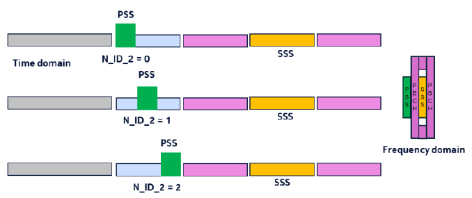
PSS is the first signal detected by the UE. It is designed for robust detection under uncertainty. The UE performs blind search over time and frequency to find PSS. Once detected, it provides coarse timing alignment and partial cell identification. This reduces the search space for subsequent steps. PSS detection is critical because it determines the starting point of the entire process.
After detecting PSS, the UE processes SSS to refine timing and frequency synchronization. SSS provides additional information required to determine the full physical cell ID. Because the UE already has partial synchronization, SSS detection requires fewer hypotheses. This makes it less complex than PSS detection. Together, PSS and SSS enable reliable cell identification.
PBCH carries the Master Information Block (MIB), which provides essential system parameters. This includes timing configuration, control channel information, and system bandwidth details. After decoding PBCH, the UE knows how to locate further system information such as SIB1. PBCH acts as a bridge between synchronization and higher layer procedures. Without PBCH, the UE cannot proceed to full access.
What additional information (e.g., cell type such as TN vs NTN) should be embedded in synchronization signals?
The document suggests that additional information may be included in synchronization signals to support new scenarios. This includes identifying cell types such as terrestrial (TN) or non-terrestrial (NTN). However, adding information must be carefully considered. It increases functionality but may also increase detection complexity.
At the initial detection stage, only essential information should be provided. This includes timing reference, coarse cell identification, and basic configuration indicators. Providing too much information at this stage increases complexity. Therefore, non-essential information should be deferred to later stages such as PBCH decoding. This keeps initial detection efficient.
Embedding additional information into synchronization signals increases processing requirements. The UE must decode more bits during the initial stage. This may require more complex detection algorithms. It can also increase the number of hypotheses. As a result, UE complexity and power consumption increase. Therefore, there is a trade-off between functionality and simplicity.
How should time-frequency resources for synchronization be designed?
Time-frequency resource design for synchronization directly impacts UE capability, detection performance, and system efficiency. The document highlights that bandwidth selection, signal placement, and transmission structure must be carefully designed. A wider bandwidth can improve detection performance, but it also increases UE complexity. At the same time, design must support different device capabilities and deployment scenarios. Therefore, time-frequency resource design becomes a key trade-off between performance, complexity, and flexibility.
What are the candidate bandwidth options for 6G initial access?
The document discusses candidate bandwidths such as 3 MHz and 5 MHz for initial access. These options reflect different trade-offs between UE capability and detection performance. The choice of bandwidth directly affects how easily the UE can detect synchronization signals.
A smaller bandwidth such as 3 MHz reduces UE requirements. It allows simpler RF design and lower processing complexity. However, it may reduce detection performance due to lower signal energy. A larger bandwidth such as 5 MHz provides better detection robustness. It increases the amount of signal energy captured by the UE. Therefore, the choice depends on the target device capability and deployment scenario.
Wider bandwidth requires higher sampling rate and more processing power. This increases hardware complexity and power consumption. Low-tier devices may not support large bandwidths efficiently. Narrow bandwidth reduces these requirements. Therefore, bandwidth selection must consider the lowest capability devices in the system. This ensures broad compatibility.
How does synchronization signal bandwidth affect complexity?
Synchronization signal bandwidth determines how much frequency space must be processed by the UE. Larger bandwidth improves detection but increases complexity. Smaller bandwidth reduces complexity but may reduce robustness. This creates a key design trade-off.
When synchronization signals occupy a larger bandwidth, more frequency space must be covered across the band. To ensure coverage, more raster points may be needed. This increases the number of possible frequency locations. As a result, the UE must search more candidates. This increases overall search complexity.
The UE must process all candidate frequency locations within the bandwidth. Larger bandwidth increases the amount of data to process. It also increases the number of hypotheses. This leads to more correlation operations and longer detection time. Therefore, wider bandwidth directly increases UE processing load.
What techniques can unify designs across bandwidths?
The document discusses the need to support multiple bandwidth options with a unified design. This avoids having completely different implementations for different bandwidths. Techniques such as puncturing can help achieve this goal.
Puncturing removes certain subcarriers from a wider bandwidth signal to emulate a narrower bandwidth. This allows the same base design to be reused. The UE can process a subset of the signal. This reduces complexity while maintaining compatibility. It enables a unified structure across different bandwidth configurations.
Removing subcarriers reduces signal energy and may degrade detection performance. This loss can be compensated using techniques such as repetition or power boosting. The design can also optimize sequence properties to improve robustness. These methods help maintain detection reliability even with reduced bandwidth.
How does fixed power spectral density (PSD) influence the trade-off between bandwidth and detection performance?
The document considers scenarios where transmit power is limited by PSD constraints. In such cases, increasing bandwidth spreads the same power over a larger frequency range. This affects detection performance and design flexibility.
Wider bandwidth allows the UE to capture more total signal energy. This can improve detection performance if power is not strictly limited. However, under PSD constraints, power per subcarrier decreases. Therefore, the benefit depends on how power is allocated. The relationship between bandwidth and SNR must be carefully evaluated.
When power is constrained by PSD, increasing bandwidth does not increase total transmit power. Instead, power is distributed over more subcarriers. This reduces per-subcarrier power. As a result, detection performance may not improve. This limits the ability to use bandwidth as a tool for improving robustness. Therefore, design flexibility is constrained.
How does synchronization signal bandwidth impact beam sweep duration?
In beam-based systems, synchronization signals are transmitted across multiple beams. The bandwidth of the signal affects how long each transmission takes. This influences the overall beam sweep duration.
Wider bandwidth typically allows shorter symbol duration in time domain. This can reduce the time required for each transmission. However, the overall structure of the synchronization block also matters. The relationship between bandwidth and time footprint must consider both frequency and time domain parameters.
Beam sweeping requires transmitting synchronization signals across multiple directions. If each transmission takes longer, total sweep duration increases. This increases access latency. If transmissions are shorter, sweeping can be faster. Therefore, bandwidth and signal design directly affect beam sweeping latency and overall access time.
How should synchronization signals (PSS/SSS) be designed?
Synchronization signal design is a central component of initial access in 6GR. The document highlights that PSS and SSS must enable reliable detection while controlling UE complexity. These signals are processed under high uncertainty in time and frequency. Therefore, their design must minimize the number of hypotheses while maintaining robustness. At the same time, they must support scalability and future extensibility. This creates multiple design trade-offs that must be carefully balanced.
What information should synchronization signals carry?
Synchronization signals provide the first information that the UE receives from the network. This information must be sufficient for detection and basic identification. However, including too much information increases complexity. Therefore, only essential information should be included at this stage.
In NR, PSS and SSS together provide the full PCI. This approach allows hierarchical detection. Including full PCI enables the UE to uniquely identify the cell early. However, it also increases the number of hypotheses. Therefore, the design must balance early identification with detection complexity. Partial identification followed by refinement may be preferred.
The system must support a large number of cells, especially in dense deployments. This requires sufficient ID space. However, increasing the number of IDs increases detection complexity. The sequence design must support scalability without degrading performance. Therefore, ID space and complexity must be jointly optimized.
Why use multiple synchronization signals?
Using multiple signals such as PSS and SSS allows the detection process to be divided into stages. This reduces complexity compared to detecting everything at once. The document highlights that hierarchical detection is an effective method to manage UE processing load.
Hierarchical detection divides the problem into smaller steps. PSS provides coarse detection with a limited set of hypotheses. SSS then refines the result. This avoids testing all combinations at once. As a result, the total number of hypotheses is reduced. This significantly lowers processing complexity.
By separating information across multiple signals, each step focuses on a subset of possibilities. For example, PSS may identify a group of cells, and SSS identifies the exact cell. This reduces the search space at each stage. The UE processes fewer hypotheses at a time. This improves efficiency and reduces power consumption.
What is the minimum necessary information that must be available at the earliest stage of cell detection?
At the initial detection stage, the UE operates under high uncertainty. Therefore, only essential information should be included. Additional information can be provided later through PBCH. This approach minimizes complexity while maintaining functionality.
Non-critical configuration information can be deferred to PBCH. This includes detailed system parameters and higher layer configuration. By deferring this information, the synchronization signals remain simple. This reduces detection complexity. It also improves robustness under uncertainty.
Providing key information early can reduce the number of search steps. For example, partial identification can narrow down candidate cells. This reduces the need for repeated searches. However, too much early information increases complexity. Therefore, only the most impactful information should be included.
Should synchronization signals support extensibility for future features?
6GR must support future evolution and new features. Therefore, synchronization signal design should consider extensibility. However, adding flexibility must not significantly increase complexity or break compatibility.
Reserved bits or flexible structures can be included in the signal design. These can be used for future extensions. This allows new features to be introduced without redesigning the signal. However, these additions must be carefully designed to avoid impacting current performance.
Extensibility must not break compatibility with existing devices. New features should be optional and backward compatible. Legacy devices should still be able to detect and process the signals. Therefore, extensibility must be implemented in a controlled manner. This ensures long-term stability of the system.
How should PSS be designed?
PSS design is one of the most critical aspects of initial access in 6GR. The document emphasizes that PSS detection dominates UE complexity because it is performed under high uncertainty. The UE does not know exact timing or frequency offset at this stage. Therefore, PSS must be designed for robust detection while minimizing computational effort. The goal is to reduce the number of hypotheses and correlation operations required during blind search.
What are the key requirements for PSS sequences?
PSS sequences must enable reliable detection under challenging conditions. They must be robust to noise, interference, and frequency offset. At the same time, they must support efficient correlation-based detection. These requirements directly impact UE complexity and detection performance.
At the initial detection stage, the UE does not have frequency synchronization. This means that the received signal may have significant frequency offset. The PSS sequence must maintain good correlation properties under this offset. If the sequence is sensitive to CFO, the UE must test more frequency hypotheses. This increases complexity. Therefore, CFO robustness is a key requirement for PSS design.
PSS detection is typically performed using time-domain correlation. The UE slides a known sequence across the received signal to find a match. This process must be efficient because it is repeated many times. Strong correlation properties allow reliable detection with fewer operations. Poor correlation properties increase false detection or missed detection. Therefore, sequence design must support efficient time-domain correlation.
What are the trade-offs between sequence types?
Different sequence types offer different advantages. The document highlights trade-offs between Zadoff-Chu sequences and m-sequences. The choice of sequence affects correlation performance, CFO robustness, and implementation complexity.
Zadoff-Chu sequences have ideal correlation properties under perfect synchronization. However, they are sensitive to frequency offset. In NR, m-sequences were adopted because they provide better robustness under CFO. This makes them more suitable for practical scenarios. The trade-off is that correlation properties are not perfect. Therefore, sequence selection depends on operating conditions.
Although m-sequences are more robust than Zadoff-Chu under CFO, they are not immune to degradation. Correlation peaks may spread or reduce in magnitude. This can make detection less reliable in extreme conditions. Therefore, additional processing or hypotheses may still be required. This highlights the importance of careful sequence design.
What PSS sequence options are being considered?
The baseline option is to keep the NR-style m-sequence. This is attractive because it avoids the correlation peak shift problem that LTE Zadoff-Chu based PSS can experience under CFO. It gives stable timing detection, but the correlation peak itself can still weaken when the residual CFO is large. Therefore, the UE may still need to test several frequency hypotheses during initial search.
The main benefit is timing stability. The correlation peak tends to stay at the same timing position even when frequency offset is present. This makes timing acquisition more reliable, especially when the UE is still doing blind search. The drawback is that detection reliability may depend on checking enough CFO hypotheses, which increases UE processing.
Another option is to shorten the PSS so that it occupies only about one third of the OFDM symbol. Concentrating the sequence in a shorter time interval can improve tolerance to frequency error and may reduce the density of CFO hypotheses. This can lower the initial search burden. However, if multiple PSS locations or multiple PSS sequences are used, some of the complexity may move to SSS detection or symbol-position hypotheses.
< R1-2603518 : Figure 3. PSS Design with 1/3 Symbol Duration >
The trade-off is between PSS detection complexity and downstream synchronization complexity. A full-symbol NR-style design is simple and timing-stable, but it may require more CFO searching. A shorter PSS can improve frequency-error tolerance, but the design must avoid creating additional ambiguity for SSS detection and cell identification.
Should the number of PSS sequences be reduced?
The document suggests that reducing the number of PSS sequences can significantly reduce UE complexity. Each sequence adds another dimension to the search space. Therefore, minimizing the number of sequences is beneficial. However, this must be balanced with the need for sufficient cell identification.
Fewer sequences mean fewer correlation operations. The UE does not need to test as many candidates. This reduces processing load and detection time. It also reduces power consumption. Therefore, limiting the number of sequences is an effective way to reduce complexity.
Reducing the number of sequences may reduce the ability to distinguish between cells. This can increase the risk of ambiguity or collision. Additional mechanisms may be needed to resolve this. Therefore, reducing sequences must be balanced with maintaining sufficient identification capability.
How does PSS design influence the number of required CFO hypotheses?
CFO uncertainty is a major contributor to detection complexity. The number of frequency hypotheses depends on how sensitive the PSS sequence is to frequency offset. Therefore, sequence design directly influences the required number of hypotheses.
If the PSS sequence maintains strong correlation under frequency offset, fewer hypotheses are needed. The UE can detect the signal even with imperfect frequency alignment. This reduces the need to test multiple CFO values. As a result, complexity decreases significantly.
Reducing the number of CFO hypotheses directly reduces the number of correlation operations. This lowers processing load and speeds up detection. It also reduces power consumption. Therefore, sequence robustness has a direct impact on UE efficiency.
How does PSS design affect UE power consumption during blind search?
Blind search is one of the most power-intensive operations in the UE. PSS design directly affects how much processing is required during this stage. Therefore, it has a strong impact on UE power consumption.
Correlation complexity scales with the number of time samples, frequency hypotheses, and sequence candidates. As any of these increases, processing effort increases. Efficient sequence design can reduce one or more of these dimensions. This helps control overall complexity.
Longer search duration means the UE remains active for a longer time. During this period, processing units consume power continuously. If detection takes too long, battery life is affected. Therefore, reducing search duration is important for energy efficiency. PSS design plays a key role in achieving this.
How should SSS be designed?
SSS design complements PSS in the synchronization process. While PSS is responsible for initial detection under high uncertainty, SSS operates after partial synchronization is achieved. The document highlights that SSS must provide reliable cell identification while maintaining good correlation properties. It must also support scalability and measurement functions. Therefore, SSS design focuses more on reliability and stability rather than reducing blind search complexity.
Why are Gold sequences used for SSS?
Gold sequences are widely used because of their good correlation properties and flexibility. The document indicates that SSS design benefits from sequences that can support a large number of IDs while maintaining detection performance. Gold sequences provide a practical balance between performance and implementation complexity.
Gold sequences have good autocorrelation properties, which help in detecting the correct timing position. They also have low cross-correlation between different sequences. This reduces interference between cells using different IDs. As a result, detection reliability improves in multi-cell environments. These properties make Gold sequences suitable for large-scale deployments.
What are the limitations of SSS under frequency offset?
Although SSS is processed after PSS detection, it is still affected by residual frequency offset. The document highlights that SSS detection assumes some level of synchronization. However, imperfect correction can degrade performance.
Residual CFO can distort the received SSS sequence. This reduces correlation peak strength and increases noise in detection. As a result, the probability of detection decreases. In severe cases, incorrect cell identification may occur. Therefore, SSS performance depends on the accuracy of frequency correction achieved during PSS processing.
What assumptions are needed for reliable SSS detection?
SSS detection assumes that the UE has already achieved partial synchronization. This includes coarse timing and frequency alignment. Without these conditions, SSS detection would require more hypotheses and become more complex.
The UE must achieve sufficient timing alignment to locate the SSS within the correct symbol. Frequency offset must also be reduced to a manageable level. If these conditions are met, SSS detection can be performed with a limited number of hypotheses. This ensures efficient processing. Therefore, PSS performance directly impacts SSS reliability.
How does SSS design impact mobility measurements (e.g., RSRP accuracy)?
SSS is not only used for detection but also for measurement. The document suggests that synchronization signals may support mobility functions. Therefore, SSS design must consider measurement accuracy in addition to detection.
Good sequence properties lead to stable correlation results. This improves consistency in signal strength measurements such as RSRP. Stable measurements are important for mobility decisions. Poor sequence quality may lead to fluctuations. This can degrade handover performance.
Residual CFO can affect amplitude and phase of the received signal. This introduces errors in measurement. The UE may underestimate or overestimate signal strength. Accurate frequency correction helps improve measurement reliability. Therefore, synchronization quality directly affects measurement performance.
How does SSS robustness affect cell-edge performance?
Cell-edge conditions are characterized by low signal strength and high interference. In these conditions, SSS detection becomes more challenging. The document implies that robust sequence design is important for maintaining performance at the edge.
Interference from neighboring cells can distort the received SSS signal. This reduces correlation peak clarity. As a result, detection becomes less reliable. Strong cross-correlation properties help mitigate this effect. Therefore, sequence design plays an important role in interference resilience.
Fading causes variations in signal amplitude and phase. This affects correlation results. In deep fading conditions, the signal may become difficult to detect. Robust sequence design and possible repetition can help mitigate this. Therefore, SSS must be designed to handle realistic channel conditions.
How should synchronization coexist with NR (MRSS scenarios)?
In MRSS scenarios, NR and 6GR systems operate in the same or nearby spectrum. The document highlights that coexistence must be carefully designed to avoid interference and excessive UE complexity. Synchronization signals from different RATs may overlap in time and frequency. Therefore, the design must ensure that UEs can distinguish between NR and 6GR signals reliably. At the same time, reuse of existing structures may improve efficiency. This creates trade-offs between compatibility, complexity, and performance.
Should 6G reuse NR synchronization raster?
Reusing NR synchronization raster can simplify UE design. It allows the UE to search for both NR and 6GR signals using a common structure. However, this also introduces challenges in distinguishing between the two systems.
If NR and 6GR use the same raster locations, the UE can reuse search results. This reduces scanning effort and simplifies implementation. However, signals from different RATs may overlap. This increases the risk of misdetection. Therefore, additional mechanisms are needed to distinguish between them.
How can interference with NR devices be avoided?
Coexistence requires minimizing interference between NR and 6GR signals. The document suggests that signal design and resource allocation must ensure separation or orthogonality where possible. This helps maintain detection reliability.
Sequences used in 6GR synchronization signals should have low cross-correlation with NR sequences. This reduces interference during detection. Orthogonality can be achieved through careful sequence design. This ensures that signals from different RATs can be distinguished. As a result, detection performance improves.
What is the impact of alignment on UE complexity?
Alignment between NR and 6GR structures affects UE search strategy. It can either reduce or increase complexity depending on how it is implemented. The document highlights that alignment must be carefully designed.
If both systems share similar timing and frequency structures, the UE can reuse detection results. This reduces the number of independent searches. As a result, processing load decreases. This improves efficiency.
When signals overlap, the UE may confuse one RAT for another. This increases the risk of false detection. Additional processing may be required to resolve ambiguity. This can offset the complexity benefits of alignment.
What mechanisms prevent false detection of 6GR signals by legacy NR UEs?
Legacy NR UEs should not falsely detect 6GR synchronization signals as valid NR signals. The document highlights the need for mechanisms to ensure backward compatibility and prevent interference.
6GR sequences can be designed to have low correlation with NR sequences. This reduces the probability that an NR UE will falsely detect them. Careful selection of sequence sets is required. This ensures compatibility between systems.
Detection algorithms can use thresholds to decide whether a signal is valid. By adjusting these thresholds, false detection can be reduced. This may involve tuning based on expected signal properties. Proper threshold design helps maintain reliability.
How does partial frequency proximity (within CFO range) affect coexistence?
When NR and 6GR signals are close in frequency, CFO effects can blur the distinction between them. This creates challenges in detection and separation. The document highlights that frequency proximity must be considered in design.
Frequency offset causes spreading of signal energy across subcarriers. When two signals are close in frequency, this spreading can cause overlap. The UE may not clearly distinguish between them. This increases detection difficulty.
Overlap and interference reduce correlation peak clarity. This increases the probability of missed detection or false detection. Detection algorithms must account for this effect. Therefore, sequence design and frequency planning must consider CFO impact.
What information should be delivered via PBCH/MIB?
PBCH/MIB provides the first layer of system information after synchronization. The document highlights that this information must be minimal yet sufficient for the UE to proceed with access. It must enable timing alignment, frequency alignment, and acquisition of further system information. At the same time, increasing MIB size increases decoding complexity and latency. Therefore, PBCH/MIB design must carefully balance functionality and simplicity.
What essential information must UE obtain during initial access?
During initial access, the UE must obtain a small set of critical parameters. These parameters allow the UE to align with the network and prepare for further decoding. The document emphasizes that only essential information should be included at this stage.
Timing information allows the UE to align its frame and symbol boundaries with the network. This includes parameters such as frame timing and subframe structure. The UE uses this information to correctly interpret subsequent transmissions. Without accurate timing, further decoding is not possible. Therefore, timing information is one of the most critical elements in MIB.
Frequency alignment is initially achieved using synchronization signals. However, PBCH provides additional configuration that refines this alignment. This may include information about subcarrier spacing and frequency resources. The UE uses this to ensure correct demodulation. Accurate frequency alignment is required for reliable decoding.
What configuration is needed for system information acquisition?
After decoding MIB, the UE must locate and decode additional system information such as SIB1. This requires specific configuration parameters. These parameters guide the UE on where and how to find the next information.
MIB provides information about the location and scheduling of SIB1. This may include time and frequency resources where SIB1 is transmitted. The UE uses this information to monitor the correct resources. Without this guidance, the UE would need to perform a blind search. Therefore, this information is essential for efficient access.
The UE needs to know how to decode control channels that carry scheduling information. This includes parameters related to PDCCH configuration. These parameters allow the UE to interpret scheduling grants. Without this, the UE cannot receive further system information. Therefore, basic control channel configuration must be included.
Should additional features be supported?
The document considers whether additional features should be included in MIB. These features may improve energy efficiency or coverage. However, adding features increases complexity and MIB size. Therefore, inclusion must be carefully justified.
Energy saving features may require additional configuration information. For example, parameters for reduced monitoring or on-demand signaling may be included. This allows the UE to operate in a more power-efficient manner. However, adding such information increases MIB size. Therefore, only essential parameters should be included.
Coverage extension may require additional repetition or configuration parameters. These parameters help the UE detect signals under weak conditions. Including such information can improve cell-edge performance. However, it also increases complexity. Therefore, trade-offs must be considered.
How should information be split between SS, PBCH, and DMRS?
The document suggests that information should be distributed across different signals and channels. This helps balance complexity and performance. Early signals should remain simple, while more detailed information can be provided later.
Synchronization signals primarily provide timing and coarse identification. PBCH carries essential configuration information. DMRS supports channel estimation for decoding. This separation allows each component to focus on a specific function. It also simplifies processing at each stage.
Splitting information across stages introduces sequential processing. The UE must complete one step before proceeding to the next. This can increase latency. However, it reduces complexity at each step. Therefore, the design must balance latency and processing efficiency.
What information enables new delivery methods (e.g., on-demand SI, fixed PDSCH)?
The document discusses new methods for delivering system information. These methods require additional configuration. The UE must know how to access these new mechanisms.
The UE must know how to access system information channels. This includes scheduling patterns and resource locations. For on-demand delivery, the UE may need trigger conditions. Without this information, the UE cannot access the new delivery methods. Therefore, key parameters must be included in MIB.
Adding new parameters increases the size of MIB. Larger MIB requires more resources to transmit and decode. This increases latency and complexity. Therefore, only critical parameters should be included. Additional information can be delivered in later stages. This helps keep MIB efficient.
How should PBCH be designed for performance?
PBCH design directly impacts coverage, detection reliability, and access latency. The document highlights that PBCH must be decodable under challenging conditions, especially at the cell edge. At the same time, it must not introduce excessive delay or UE complexity. Therefore, PBCH design involves trade-offs between payload size, repetition, and combining efficiency. The goal is to maximize decoding probability while keeping latency and processing manageable.
How does PBCH allocation size affect coverage?
PBCH allocation size is another coverage-related design factor. If the PBCH occupies more symbols or more bandwidth, the coded information can be spread over more resources. This improves the SNR required for one-shot decoding, but it also consumes more SSB resources and may increase the number of allocation hypotheses that the UE has to consider.
< R1-2603518 : Figure 9. Illustration of considered PBCH allocation options >
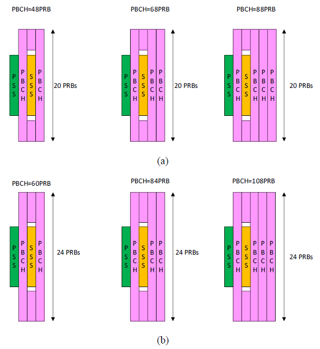
Increasing the PBCH allocation by one or two OFDM symbols gives a clear coverage benefit. For the 20 PRB case, moving from the NR-like 48 PRB allocation to 68 PRBs improves the required SNR by about 1.5 dB. Moving to 88 PRBs improves it by about 2.4 to 2.5 dB. This shows that symbol extension is effective when the goal is to improve one-shot PBCH reliability.
Increasing the PBCH bandwidth from 20 PRBs to 24 PRBs gives a smaller benefit when the number of symbols is unchanged. The SNR improvement is roughly 0.9 dB. However, combining wider bandwidth with additional symbols gives a larger gain. The 108 PRB case, based on 24 PRBs with two additional symbols, improves the required SNR by about 3 dB compared with the NR-like baseline.
Larger PBCH allocations improve coverage, but they make the SSB structure heavier. A wider PBCH such as 24 PRBs may also create many possible allocation hypotheses if the channel bandwidth is small and blind detection is assumed. Therefore, the benefit is not only an SNR question. The design must also consider UE search complexity, SSB size, and whether the PBCH location can be derived from the PSS/SSS structure without excessive hypotheses.
What is the role of PBCH payload size?
PBCH payload size determines how much information is delivered in the Master Information Block. A larger payload provides more functionality but increases decoding difficulty. A smaller payload improves robustness but limits flexibility. Therefore, payload size must be carefully chosen.
A larger payload requires more bits to be transmitted. This increases the required signal-to-noise ratio for successful decoding. As a result, coverage may decrease, especially at the cell edge. A smaller payload improves decoding probability under weak signal conditions. Therefore, reducing payload size can improve coverage performance.
What is PBCH combining and why is it important?
PBCH combining refers to combining multiple receptions of the same signal to improve decoding reliability. This is especially important in low SNR conditions. The document highlights that combining is a key technique for improving coverage.
Combining increases the effective signal energy by aggregating multiple transmissions. This improves the signal-to-noise ratio. As a result, decoding becomes more reliable. This is particularly useful at the cell edge where signal strength is low.
Efficient combining requires that multiple transmissions are sufficiently similar. This includes consistent channel conditions and timing alignment. If channel variation is too large, combining efficiency decreases. Therefore, transmission design must consider channel stability and coherence time.
Should PBCH payload be time-invariant?
The document considers whether PBCH payload should remain constant over time. A time-invariant payload simplifies combining and reduces UE complexity. However, it may limit flexibility in updating system information.
If the payload remains the same across repetitions, the UE can combine signals without additional processing. It does not need to track changes in content. This reduces complexity and improves decoding efficiency. Therefore, time-invariant payload supports simpler UE implementation.
How does PBCH repetition pattern affect latency vs coverage trade-off?
Repetition improves decoding reliability but increases transmission time. The document highlights that repetition must be carefully designed to balance coverage and latency. More repetitions improve coverage but delay access.
Each repetition provides another opportunity to receive the signal. The UE can combine multiple repetitions to improve SNR. This increases the probability of successful decoding. Therefore, repetition is an effective method to enhance coverage.
Repetition spreads the transmission over a longer time period. The UE may need to wait for multiple repetitions before decoding. This increases access latency. Therefore, increasing repetition improves reliability but delays access.
How does clustering of PBCH occasions impact combining efficiency?
The document discusses how the timing of PBCH transmissions affects combining. Clustering refers to placing multiple transmissions close in time. This can improve combining efficiency under certain conditions.
When transmissions are close in time, channel conditions are similar. This allows coherent combining. However, diversity gain may be limited because channel variation is small. If transmissions are spread out, diversity increases but combining becomes more complex. Therefore, timing affects the trade-off between coherence and diversity.
The UE must store received signals before combining. If transmissions are spread out, the UE must buffer data for a longer time. This increases memory requirements. If transmissions are clustered, buffering requirements are reduced. Therefore, clustering can simplify UE implementation.
How should synchronization periodicity and patterns be designed?
Synchronization periodicity and transmission patterns directly affect energy efficiency, access latency, and UE complexity. The document highlights that increasing periodicity is a key method to reduce always-on signaling. However, this introduces trade-offs in detection delay and processing effort. In addition, the structure of transmission patterns, such as clustering, affects combining efficiency and resource usage. Therefore, periodicity and pattern design must balance energy saving, performance, and resource efficiency.
What are the benefits of increasing SS/PBCH periodicity?
Increasing periodicity reduces how often synchronization signals are transmitted. This lowers network activity and improves energy efficiency. The document emphasizes this as a key goal in 6GR design.
When synchronization signals are transmitted less frequently, the network can remain idle for longer periods. This reduces transmit power usage. It also enables deeper sleep modes. Over time, this leads to significant energy savings. This is especially important in large-scale deployments.
What are the drawbacks?
Although increasing periodicity improves energy efficiency, it introduces several challenges. These include increased latency and higher UE complexity. Therefore, the design must carefully consider these trade-offs.
With longer periodicity, the UE may need to wait longer for the next synchronization signal. If the UE arrives just after a transmission, it must wait until the next one. This increases access delay. In worst cases, the delay equals the full periodicity. Therefore, latency becomes less predictable.
Longer periodicity increases uncertainty in timing. The UE must search over a wider time window. This increases the number of time hypotheses. Combined with frequency hypotheses, the search space grows. As a result, processing complexity increases. This also increases power consumption.
What is clustered transmission?
Clustered transmission refers to grouping multiple synchronization signal transmissions within a short time interval. Instead of spreading transmissions evenly, they are concentrated in a cluster. This structure can improve combining efficiency and reduce UE complexity in some cases.
Multiple transmissions within a short interval allow the UE to combine signals effectively. Since channel conditions are similar, combining is more efficient. This improves detection probability. It also reduces the need for long-term buffering. Therefore, clustering can enhance reliability.
Clustering reduces time diversity because transmissions occur close together. If channel conditions are poor, all repetitions may be affected. Spreading transmissions increases diversity but reduces combining efficiency. Clustering also increases short-term resource usage. Therefore, there is a trade-off between diversity and overhead.
How does synchronization periodicity affect measurement accuracy?
Synchronization signals are also used for measurements such as RSRP. Therefore, periodicity affects how often the UE can update measurements. The document highlights that sparse signaling may impact measurement accuracy.
With less frequent signals, the UE has fewer opportunities to update measurements. This makes tracking of channel conditions less accurate. Rapid changes in the channel may not be captured. This can affect link adaptation and synchronization maintenance. Therefore, measurement accuracy decreases with sparse signaling.
Mobility decisions rely on measurement reports. If measurements are infrequent or inaccurate, decisions may be delayed or incorrect. This can lead to suboptimal handovers. In extreme cases, connection quality may degrade. Therefore, periodicity must support reliable mobility performance.
How does clustering impact resource availability for data transmission?
Synchronization signals occupy time-frequency resources that could otherwise be used for data. Clustering affects how these resources are distributed over time. The document highlights that this has implications for system throughput.
When transmissions are clustered, a larger portion of resources is occupied in a short time. This creates a temporary reduction in available resources for data. Outside the cluster, resources are free. Therefore, resource usage becomes uneven over time.
Short-term clustering may reduce instantaneous throughput during transmission periods. However, longer idle periods allow efficient scheduling of data. Overall throughput impact depends on how resources are managed. Therefore, clustering must be designed to minimize negative impact on data transmission.
How should SSB candidate locations be patterned?
SSB candidate locations are important because the UE must know where synchronization opportunities may appear before it can search efficiently. In NR, these locations are fixed within a slot and help the UE establish timing. For 6GR, fixed candidate locations can still be useful, especially if PBCH combining or SSB beam-sweep combining is expected. Without predictable candidate locations, the UE may need to test more timing hypotheses, which increases complexity.
Fixed locations reduce uncertainty. They allow the UE to search only a limited set of symbol and slot positions instead of scanning a wider time window. This is useful when SSB periodicity is extended, because fewer SSB occasions are available and each missed opportunity has a larger latency impact. Therefore, fixed candidate locations can help preserve detection reliability while keeping UE processing manageable.
How should symbol-level SSB locations be simplified?
NR symbol-level SSB locations were selected with several constraints in mind, including DL control at the start of a slot, UL control near the end of a slot, mixed numerology, mini-slot operation, and different TDD cases. For 6GR, some of these constraints may be relaxed. For example, if mixed numerology is not a prerequisite in FR1, the reserved symbols for DL control and SSB placement can be reconsidered.
< R1-2603518 : Figure 10. Illustration of NR SSB candidate locations within a slots for μ={0,1,2,3,4} >
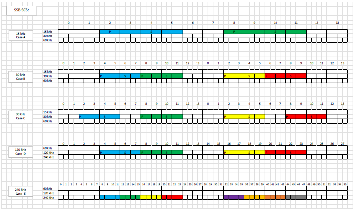
Using two SSB candidate locations in a slot can reduce beam sweep duration. This is useful when many beams must be transmitted and when the system wants to limit the total synchronization sweep time. Reserving a small number of symbols for DL control can still help multiplex SSB with other transmissions, but reserving UL control symbols at the end of every slot may not be needed in most slots.
A gap between SSB candidates does not appear necessary for many FR1 and FR2-1 cases. Avoiding unnecessary gaps can simplify the symbol pattern and make the candidate locations more compact. Special slots still need separate handling, because UL symbols and guard periods can reduce the number of usable SSB locations.
How should slot-level SSB patterns handle TDD constraints?
Slot-level SSB patterns must be aligned with the actual UL/DL slot structure. A pattern that works for one TDD configuration may collide with special slots or UL symbols in another configuration. Therefore, the relationship between SSB slot pattern and TDD UL/DL slot pattern needs to be considered explicitly in 6GR.
< R1-2603518 : Figure 11. Illustration of NR slot level SSB pattern for μ={0,1,2,3,4} >
< R1-2603518 : Figure 12. Illustration of required number of slots to reach actual number of possible SSB candidate locations, Lactual, equal to {16,32} with two alternative TDD patterns >
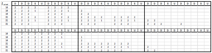
In NR, SSBs can be placed across a set of continuous slots. This is simple, but it may not align well with practical TDD patterns such as slots reserved for UL or special-slot operation. If some candidate locations cannot be used, the effective number of SSB occasions is reduced. This can limit the number of beams supported within a target time window such as 5 ms.
A TDD-agnostic SSB pattern is simpler from a specification perspective, but it may require more candidate locations to guarantee enough actually usable SSB occasions. A TDD-aware pattern can reduce unused candidates, but it depends on the configured UL/DL pattern and special-slot assumptions. Therefore, there is a trade-off between common design and efficient use of usable slots.
How do SSB repetitions affect combining and beam sweep duration?
If repetitions are transmitted before completing a beam sweep, the UE may be able to combine repeated SSBs more easily. However, this can extend the time required to cover all beams. If the beam sweep is completed first and then repeated, the measurement gap may be shorter, but the UE may need additional assumptions about repetition timing and candidate locations.
Inter-frequency measurements are sensitive to the total duration of the synchronization sweep. If SSB repetitions cause the sweep to exceed the available measurement gap, the UE may not be able to measure all beams efficiently. Therefore, the mapping between repetitions and SSB candidate locations must consider both combining gain and measurement feasibility.
How should clustered SSB transmissions be used?
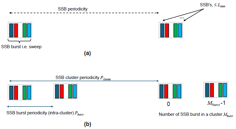
Clustered SSB transmission is a way to support long SSB periodicity while still giving the UE multiple synchronization opportunities within a shorter interval. Instead of spreading individual SSB occasions uniformly over time, the network can transmit a cluster at the start of a longer period. This can reduce the average latency for acquiring enough SSB occasions for measurements or PBCH decoding.
< R1-2603518 : Examples of Clustered SSB Transmission >
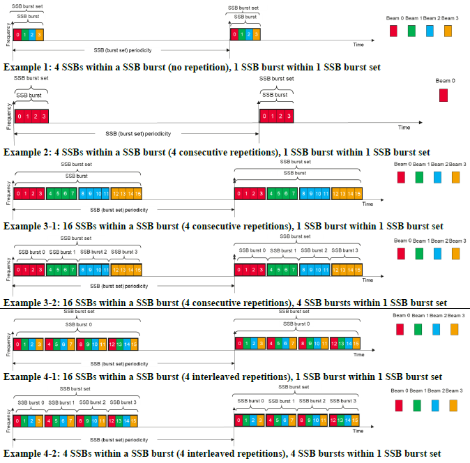
< R1-2603518 : Figure 14. Illustration of (a) legacy NR SSB transmission pattern and (b) clustered SSB transmission pattern >
< R1-2603518 : Figure 15. Illustration of possible combining over clusters and within a cluster based on Pcluster and Pburst >
The useful distinction is between an SSB burst, an SSB burst set, and repetitions within the burst set. A 6GR SSB burst can contain multiple 6GR SSBs, while a burst set can contain one or more bursts. Repetitions may occur consecutively or with time separation inside the cluster. These definitions help describe whether the UE is seeing different beams, repeated transmissions, or multiple burst groups.
When the SSB periodicity is extended to values such as 80 ms or 160 ms, a UE may otherwise wait a long time to collect enough SSB occasions. Clustering can place multiple occasions near the beginning of the period. This can reduce average acquisition latency, especially when the UE needs several SSB occasions for measurement, tracking, or PBCH combining.
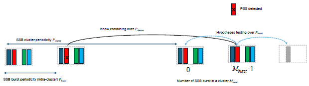
What UE assumptions are needed for clustered SSB operation?
Clustered operation should minimize the amount of prior information required by the UE. For PSS detection, the UE can still perform blind search without strict assumptions about the cluster. For SSS detection, the UE may use the detected PSS timing and then try SSS detection based on the expected SSB structure. For PBCH combining, more information is useful because the UE needs to know which SSBs can be combined.
The UE benefits from knowing the SSB cluster periodicity and the repetition periodicity within the cluster. With this information, it can combine PBCH over likely repetition candidates. Without it, the UE may need to test more hypotheses across SSB burst locations, which increases complexity. Therefore, clustered SSB operation should define enough timing structure to make combining practical.
Repeated synchronization signals and channels can help create self-detectable or decodable SS/PBCH occasions within a cluster. This is useful because the UE may not need full prior knowledge of every repetition if the repeated occasions can be detected from the signal structure itself. The design still needs to define how many repetitions are used, whether all repetitions are identical, and how far apart they are placed.
How does beam-based operation impact synchronization?
Beam-based operation is a fundamental feature of 6GR, especially at higher frequencies. The document highlights that synchronization must now be performed across multiple spatial directions. This significantly impacts how synchronization signals are transmitted and detected. Instead of omnidirectional transmission, signals are beamformed and swept across directions. This increases both transmission overhead and UE search complexity. Therefore, synchronization design must consider beam management as a core factor.
Why are more beams needed at higher frequencies?
At higher frequencies, signal propagation characteristics change. Path loss increases and signals become more directional. As a result, beamforming is required to maintain coverage. This leads to an increase in the number of beams that must be supported.
Higher frequencies allow more antenna elements to be packed into the same physical area. This enables narrow beamforming. Narrow beams provide higher gain but cover smaller spatial regions. Therefore, more beams are required to cover the entire cell. This increases the number of beam directions that must be scanned during synchronization.
How many SS/PBCH beams should be supported?
The number of SS/PBCH beams determines how many directions synchronization signals are transmitted. The document suggests that increasing beam count improves coverage but increases overhead. Therefore, the number of beams must be carefully chosen.
NR already supports beam sweeping for synchronization, especially in FR2. However, 6GR may require even more beams due to higher frequencies and narrower beams. This increases both transmission and detection complexity. Therefore, scaling beyond NR requires new optimizations.
How many broadcast beams may be needed around 7 GHz?
For new frequency ranges around 7 GHz, one objective is to keep a similar site grid to existing FR1 deployments. This requires enough antenna gain to compensate for the higher path loss compared with lower FR1 frequencies. If the physical array size remains similar, the number of antenna elements can increase, which narrows the beamwidth and increases the number of beams needed to cover the same area.
If the number of antenna elements is doubled in both horizontal and vertical dimensions, the number of possible beams can increase by about four times. Therefore, if FR1 supports up to eight SS/PBCH beams, a similar coverage target around 7 GHz may require support for 16 or 32 SS/PBCH beams. This improves coverage but also increases synchronization overhead and UE search effort.
How does subcarrier spacing affect beam transmission?
Subcarrier spacing affects symbol duration and transmission timing. This has implications for beam sweeping and synchronization overhead. The document highlights that higher SCS can reduce time-domain overhead.
Higher SCS results in shorter symbol duration. This allows faster transmission of synchronization signals. In beam sweeping, this reduces the total time required to cover all beams. Therefore, higher SCS improves efficiency in high-frequency scenarios.
Shorter symbols mean that each beam transmission occupies less time. When multiple beams are transmitted sequentially, total duration decreases. This reduces synchronization overhead. As a result, access latency can be improved.
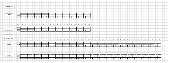
Why consider 240 kHz SCS for SS/PBCH in FR2-1?
For FR2-1 operation, especially when 120 kHz SCS would otherwise be used, 240 kHz SCS can reduce the time-domain footprint of SS/PBCH. This is useful for analog beamforming, where many SSB beams may need to be swept. If 64 SSB beams are transmitted, using 240 kHz SCS can reduce the burst duration compared with 120 kHz SCS.
< R1-2603518 : Figure 16. Mapping of SSBs with 120 and 240 kHz SCSs, respectively, in a 14-symbol slot defined by 120 kHz SCS >

< R1-2603518 : Figure 17. NR mapping of SSBs into 14 symbol slots with 120 and 240 kHz SCSs within 5 ms half-frame >
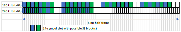
With 120 kHz SCS, fewer SSBs fit into a 14-symbol slot. With 240 kHz SCS, more SSBs can be mapped into the same slot duration because each symbol is shorter. As a result, the number of affected slots within a given time window can be reduced. This creates more opportunities for scheduling PDSCH and other downlink transmissions.
How does SS/PBCH SCS affect downlink resource overhead?
SSB transmissions are usually broadcast and periodic. They are intended to cover the cell even when there may not be active UEs under every beam. In analog beamforming, this can limit data multiplexing because the beam direction used for SSB may not match the beam direction needed for PDSCH. Therefore, the time-domain footprint of SSB directly affects available downlink resources.
FDM between SSB and PDSCH is not always practical with analog beamforming. The gNB may only be able to transmit data toward a beam direction aligned with one of the SSBs in the slot. For other SSB beams, the same symbols may effectively be unavailable for PDSCH scheduling. This makes the SSB footprint a real cell-level overhead, not only a physical resource mapping issue.
The numerical examples show that 240 kHz SCS can reduce the percentage of downlink resources affected by SSB compared with 120 kHz SCS. For a 64-beam, 20 ms SSB burst case, 120 kHz SCS affects about 32 out of 160 slots, while 240 kHz SCS affects about 16 out of 160 slots. This reduces SSB-related overhead and improves the amount of resource available for PDSCH.
| BW | Case 1 gain | Case 2 gain | Case 3 gain |
|---|---|---|---|
| 100 MHz | 3.16% | 5.34% | 11.9% |
| 200 MHz | 2.54% | 4.66% | 11.9% |
| 400 MHz | 2.23% | 4.33% | 11.9% |
For FR2-1 and possibly upper bands around 15 GHz, 240 kHz SCS for SS/PBCH can improve spectral efficiency by reducing the SSB time-domain footprint. The trade-off is that the design must still align with the SCS assumptions for other channels and signals in the band. Therefore, SS/PBCH SCS should be selected together with beam count, analog beamforming constraints, and downlink multiplexing assumptions.
How does analog beamforming limit multiplexing of SSB and data?
In analog beamforming, a single beam direction is typically used at a time. This limits the ability to transmit multiple signals simultaneously in different directions. The document highlights that this constraint affects how synchronization and data transmissions are scheduled.
Frequency division multiplexing assumes that different signals can be transmitted simultaneously in the same time slot. However, with analog beamforming, the antenna can only focus in one direction at a time. Therefore, transmitting synchronization and data simultaneously in different beams is not straightforward. This limits multiplexing flexibility.
Since only one beam direction can be active at a time, transmissions must be scheduled sequentially. This affects both synchronization and data transmission. The network must decide when to transmit synchronization signals versus data. This introduces scheduling constraints and potential inefficiencies.
How does beam count scaling affect synchronization overhead?
As the number of beams increases, synchronization overhead also increases. Each beam requires its own transmission opportunity. This affects both network resource usage and UE search effort.
Each beam requires a separate transmission of synchronization signals. As the number of beams increases, total transmission time increases. This consumes more time-frequency resources. As a result, less resource is available for data transmission.
The UE must search across all possible beam directions. This increases the number of hypotheses. Detection time increases as more beams are scanned. This also increases UE power consumption. Therefore, beam count directly impacts UE complexity and energy usage.
How should broadcast channels be delivered?
Broadcast channel delivery is a key part of initial access and system operation. The document highlights that traditional always-on broadcast mechanisms may not be efficient for 6GR. Instead, more flexible delivery methods are needed. These include periodic and on-demand approaches. The design must balance energy efficiency, latency, and UE complexity. It must also support different deployment scenarios and scalable system information delivery.
What are the options for system information delivery?
System information can be delivered using different methods depending on system requirements. The document discusses both periodic and on-demand approaches. Each method has its own advantages and trade-offs.
On-demand SIB1 is transmitted only when needed. The UE may request system information or receive it based on network triggers. This reduces unnecessary transmissions. As a result, network energy consumption decreases. However, it requires additional signaling and coordination. This may introduce additional latency.
Periodic SIB1 is transmitted at regular intervals regardless of UE demand. This ensures that the UE can access system information without requesting it. It simplifies UE operation. However, it leads to continuous transmission even when no UE is present. This reduces energy efficiency.
How does on-demand delivery improve energy efficiency?
On-demand delivery reduces unnecessary broadcast transmissions. The network transmits system information only when required. This aligns with 6GR goals of reducing always-on signaling. However, it introduces trade-offs in latency and complexity.
With on-demand delivery, the UE may need to wait for system information to be transmitted after a request. This increases access delay compared to periodic transmission. The delay depends on scheduling and signaling procedures. Therefore, energy efficiency is improved at the cost of increased latency.
What deployment scenarios must be supported?
Broadcast delivery must work across different deployment scenarios. The document highlights that standalone and multi-cell environments have different requirements. Therefore, the design must be flexible.
In standalone scenarios, the UE relies entirely on a single cell for system information. Therefore, broadcast delivery must be self-contained. In multi-cell scenarios, system information may be distributed across cells. One cell may provide synchronization, while another provides system information. This allows more flexible and efficient delivery. However, it requires coordination between cells.
How can area-specific system information be supported?
The document suggests that system information may vary across geographic areas. Therefore, mechanisms are needed to deliver area-specific information efficiently. This avoids unnecessary transmission of irrelevant information.
The network can divide coverage into smaller regions. Each region may have different system information. The UE must identify which region it belongs to. This allows it to receive only relevant information. This reduces overhead and improves efficiency.
The UE may use identifiers or indicators provided during initial access. These indicators point to the correct system information. The UE then monitors specific resources for relevant data. This avoids unnecessary decoding of unrelated information. As a result, UE processing load is reduced.
What mechanisms allow UE to request system information without anchor cells?
In flexible architectures, the UE may not rely on a fixed anchor cell. Instead, it may need to request system information dynamically. The document highlights the need for mechanisms to support this.
The UE may send a request signal indicating its need for system information. This signal must be simple and efficient. The network then schedules the delivery of requested information. This enables on-demand operation without continuous broadcasting.
Initial configuration must be provided through synchronization signals or minimal broadcast information. This allows the UE to know how to request further information. Without this, the UE cannot initiate the request process. Therefore, a minimal bootstrap mechanism is required.
How can coverage be extended for broadcast channels?
Coverage extension is a key requirement for 6GR, especially for scenarios such as LPWA and NTN. The document highlights that broadcast channels must be decodable even under very low signal conditions. This requires techniques that improve detection probability without excessive complexity. At the same time, these techniques must not significantly increase latency or resource usage. Therefore, coverage extension design involves trade-offs between robustness, efficiency, and delay.
What techniques enable coverage extension?
Several techniques can be used to improve coverage. These include repetition, power boosting, and simplified transmission structures. The document focuses on repetition as a primary method. However, the choice of technique depends on system constraints.
Repetition increases the probability that the UE successfully receives the signal. Multiple transmissions allow combining, which improves effective SNR. This is particularly useful at the cell edge. However, repetition increases transmission time and resource usage. Therefore, it improves coverage at the cost of latency and efficiency.
Both control and data channels may require repetition to ensure reliable decoding. Repeating only one may not be sufficient. For example, if PDCCH is not reliably decoded, the UE cannot access PDSCH. Therefore, both may need to be repeated in coverage-limited scenarios. This increases overhead but ensures end-to-end reliability.
When is fixed allocation preferable?
Fixed allocation refers to predefined resource locations for broadcast channels. This simplifies UE operation because it eliminates the need for dynamic scheduling. The document suggests that this can be beneficial in coverage-limited scenarios.
With fixed allocation, the UE knows exactly where to look for broadcast channels. This eliminates the need to decode control information first. It reduces the number of search steps. As a result, UE complexity and power consumption decrease. This is especially useful for low-power devices.
How does coverage extension differ between LPWA and NTN scenarios?
LPWA and NTN scenarios have different characteristics. Therefore, coverage extension techniques must be adapted accordingly. The document highlights differences in propagation conditions and delay constraints.
In LPWA scenarios, coverage extension is needed for indoor or deep coverage. Signal attenuation is moderate but persistent. In NTN scenarios, signals travel very long distances. Path loss and Doppler effects are significant. Therefore, NTN requires more robust techniques such as higher repetition or stronger signals. LPWA may rely more on simplified processing.
LPWA applications may tolerate higher latency due to low data rate requirements. NTN scenarios also tolerate delay due to long propagation time. However, the reasons differ. In NTN, delay is inherent to the system. In LPWA, delay is a design choice. Therefore, periodicity and repetition can be adjusted differently for each case.
How does extremely long periodicity (e.g., 160 ms) impact synchronization strategy?
The document considers very long periodicity as a way to reduce energy consumption. However, this introduces new challenges for synchronization and detection. The UE must adapt its behavior to handle such conditions.
With very long periodicity, the UE may only have a single opportunity to detect the signal within a long interval. It cannot rely on combining multiple closely spaced transmissions. Therefore, detection must succeed in one attempt. This requires strong signal design and robust detection algorithms.
The UE must carefully schedule its wake-up time to coincide with signal transmission. If it misses the transmission, it must wait for the next period. This increases latency. Accurate timing knowledge is required to avoid unnecessary wake-ups. Therefore, synchronization and scheduling become more critical.
What additional signals are needed for synchronization?
The document highlights that relying only on SS/PBCH may not be sufficient for all scenarios in 6GR. As periodicity increases and energy efficiency becomes a priority, additional synchronization signals may be needed. These signals can support specific functions such as paging, system information acquisition, and RACH. They can also enable more flexible and efficient operation. Therefore, the design must consider when and how to introduce additional signals without increasing unnecessary complexity.
When are on-demand synchronization signals useful?
On-demand synchronization signals are transmitted only when needed. This reduces continuous transmission and improves energy efficiency. The document suggests that such signals can be useful in specific procedures where synchronization must be refreshed.
Before paging, the UE may need to re-align with the network. On-demand synchronization signals can be transmitted just before paging occasions. This allows the UE to wake up and synchronize only when needed. As a result, UE power consumption is reduced. It also reduces the need for continuous monitoring of SS/PBCH.
When the UE needs to acquire system information, synchronization may need to be refreshed. On-demand signals can provide this support. This allows the UE to avoid continuous scanning. It also improves efficiency in idle or inactive states. Therefore, on-demand synchronization supports flexible system information delivery.
Are additional signals needed for RACH?
Random access requires accurate timing alignment. The document considers whether additional synchronization support is needed for this procedure. This depends on the limitations of existing mechanisms.
Msg1 is transmitted without full timing alignment. This can lead to timing uncertainty. In challenging conditions, this may reduce success probability. Additional synchronization signals can help refine timing before RACH. This improves reliability of initial access attempts.
How can synchronization be maintained in carrier aggregation?
In carrier aggregation, multiple carriers may be used simultaneously. Not all carriers may transmit SS/PBCH. Therefore, synchronization must be maintained across carriers using alternative methods.
In some cases, secondary cells may not transmit SS/PBCH. The UE relies on synchronization from the primary cell. Additional signals such as CSI-RS may be used to maintain synchronization. This reduces overhead on secondary carriers. However, it requires coordination between cells.
What is the trade-off between UE-triggered and network-triggered synchronization signals?
Synchronization signals can be triggered either by the UE or by the network. Each approach has advantages and disadvantages. The document highlights that the choice depends on system requirements.
UE-triggered signals are useful when synchronization is needed on demand. This reduces unnecessary transmissions. Network-triggered signals are useful for scheduled operations such as paging. They provide predictable timing. Therefore, each approach is suitable for different scenarios.
UE-triggered signals require additional signaling for request and response. This increases control overhead. Network-triggered signals avoid this overhead but may result in unnecessary transmissions. Therefore, there is a trade-off between flexibility and efficiency.
How does wake-up signal (WUS) interaction affect synchronization design?
Wake-up signals are used to reduce UE power consumption. They allow the UE to wake up only when needed. The document suggests that WUS must be coordinated with synchronization signals.
WUS allows the UE to remain in low-power mode most of the time. It wakes up only when necessary. This reduces continuous monitoring of synchronization signals. As a result, battery life is improved. This is especially important for low-power devices.
WUS timing must align with synchronization signal transmission. If SS periodicity is long, WUS must ensure that the UE wakes up at the correct time. This requires accurate scheduling. Proper coordination ensures that the UE does not miss synchronization opportunities. Therefore, WUS and SS design must be integrated.
How should mobility measurements be supported?
Mobility measurements are essential for cell selection, reselection, and handover. The design must ensure accurate, stable, and low-latency measurements across different UE states. It must also balance measurement accuracy with UE complexity and power consumption. Therefore, the system should reuse existing signals where possible and introduce new mechanisms only when necessary.
What signals are used for measurements in NR?
SSS provides cell identity information. It is robust and always transmitted as part of SS/PBCH. It allows reliable detection even in low SNR conditions. Therefore, it is well suited for initial detection and mobility measurements. It also simplifies UE implementation since it is always available.
CSI-RS is more flexible but also more complex. It may not always be present or configured. It requires additional signaling and processing. Therefore, it is less suitable for basic mobility. It is mainly used when more accurate channel information is needed, such as for beam management.
Should synchronization signals be reused for mobility?
Reusing synchronization signals simplifies the design. It avoids introducing additional measurement signals. This reduces overhead and UE complexity. The UE does not need to track multiple signal types. Measurement procedures become more consistent across states. As a result, implementation becomes simpler and more power efficient.
What measurement quantities are important?
SS-RSRP measures received signal power. It reflects coverage level. SS-RSRQ combines signal strength and interference. It reflects quality. SS-SINR measures signal-to-interference-plus-noise ratio. It reflects link reliability. Together, they provide a complete picture of radio conditions for mobility decisions.
How should measurements be consistent across RRC states?
Measurements should behave similarly in idle, inactive, and connected states. This avoids abrupt changes in behavior. It also improves prediction accuracy. Therefore, consistent measurement definitions and procedures are important.
How can early CSI acquisition be integrated into mobility procedures?
Early CSI acquisition allows the UE to gather channel information before handover. This can be done using pre-configured CSI-RS. The UE already has channel knowledge when the handover starts. This reduces uncertainty and improves link setup speed. As a result, handover success probability increases.
Without early CSI acquisition, the UE must measure the target cell after handover. This adds delay before stable communication can begin. With early acquisition, measurements are already available. Therefore, the UE can adapt more quickly and overall handover latency is reduced.
How does measurement design impact handover stability across RRC states?
Ping-pong occurs when measurements fluctuate around mobility thresholds. Consistent filtering, reporting, and decision logic reduce rapid changes in the measured result. This stabilizes handover decisions. As a result, unnecessary back-and-forth handovers can be avoided.
In idle state, reselection depends on measured signal strength and quality. Stable and accurate measurements help the UE choose the most suitable cell. This improves user experience and reduces unnecessary reselection attempts. It also lowers signaling overhead.
How can AI/ML be integrated into 6GR initial access?
AI/ML can enhance initial access by improving efficiency, reducing latency, and lowering UE complexity. It enables predictive and adaptive behavior instead of exhaustive search. The design must ensure that AI/ML integration does not increase signaling overhead or implementation complexity. Therefore, AI/ML should complement existing mechanisms rather than replace them.
How can AI/ML improve beam selection during initial access?
AI/ML can predict the most likely beam directions based on context such as location, history, and environment. This reduces the need for exhaustive beam sweeping. The UE can focus on a subset of candidate beams. As a result, search complexity and power consumption are reduced.
How can prediction models improve synchronization timing?
Spatial prediction allows the UE to estimate the best beam direction before receiving synchronization signals. This reduces the number of beams that need to be monitored. Therefore, synchronization overhead is reduced.
The UE or network can store past beam selections and mobility patterns. These patterns can be used to predict future beam directions. This is especially useful in repetitive environments such as daily commute routes. As a result, beam acquisition becomes faster and more reliable.
Instead of scanning all beams, the UE scans only predicted beams. This reduces the number of measurements required. It also reduces latency during initial access. Therefore, prediction directly improves efficiency.
How can temporal prediction reduce latency in system information acquisition?
AI/ML can learn periodic patterns of system information transmission. The UE can predict when SI will be transmitted. This allows the UE to wake up only at the expected time. As a result, waiting time is reduced.
Without prediction, the UE may wait for the next SI window. This can introduce delay. With prediction, the UE aligns its reception with the expected transmission time. Therefore, system information can be acquired faster.
Which Rel-19 AI/ML beam management techniques can be reused in 6GR?
Rel-19 introduces AI/ML-assisted beam management techniques. These include models for beam prediction, selection, and tracking. They are designed to improve performance while keeping signaling manageable.
These models can be extended to the initial access phase. Instead of using them only for connected mode beam management, they can guide synchronization and access procedures. This allows reuse of existing frameworks. As a result, standardization effort is reduced and interoperability is improved.
Reference
- R1-2600032 : TSG RAN WG1 #124 - On Synchronization Acquisition and Beam Measurement
- R1-2600051 : TSG RAN WG1 #124 - 6G Synchronization Acquisition and Beam Measurement
- R1-2603518 : TSG RAN WG1 #125 - On Synchronization Acquisition and Beam Measurement