|
Embedded System - Arduino |
|||||||||||||||||||||||||||||||||||||||||||||||||||||||||||
|
LCD 16 x 2
This is a tutorial to show you on how to operate LCD 16 x 2 (indicating the pannel with 2 lines of character string and each line can display 16 chars). At first, I didn't like much of this application mainly because it would take up too many I/O pins. I thought it would be a little bit of waste of the hardware resources just to operate this simple LCD pannel. So, at the beginning I tried to find the same LCD pannel that has I2C interface so that I can operate it with much small number of pins. But I couldn't find such a module at the local hardware shop... finally I decided to use the module with 16 pins as it is and I thought I would learn something.
The module that I purchased is LCD-01 from OSEPP. However, I couldn't find any detailed technical documentation on this module at OSEPP home page. However, it worked with Arduino default Sample sketch.
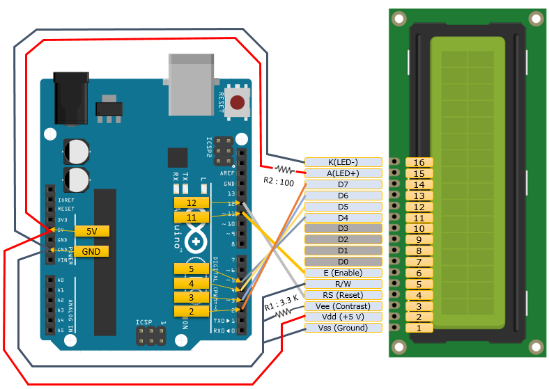
Following is the connection diagram between my Arduino and the LCD module (Sorry.. it is messy diagram.. but I didn't find any nicer way with no crossovers of wires. When you build real circuit, you would need to use a breadboard since many wires are connected to single pin GND and 5V in the diagram. It would not be possible to connect like this without using a breadboard unless you have brached wires).
NOTE : This connection diagram is a little bit different from the one shown in Arduino "Hello World" example page. It is because I forgot buying a variable resistor and I found I don't have the exact the same fixed value resistor as in the "Hello World" page. Fortunately, I got this drawing working after a little bit of struggly. The biggest difference is that I connected PIN 3 to ground (not to 5V). But you would need to put some resitor between PIN 3 and GND. I tried the direct connection without resistor.. but it didn't work (I saw some discussion page on the web suggested the direct connection to ground, but it didn't work for me). Another difference is the resistor value between PIN 15 and 5V. This is because I didn't have the exactly same resitor as in Hello World example. NOTE : Since Pin 15 and 16 is to turn on Backlight of the LCD pannel. The display would work even if you don't connect these two pins. It would be just a little difficult to read the characters since the screen gets too dark.
Running a Sample Program
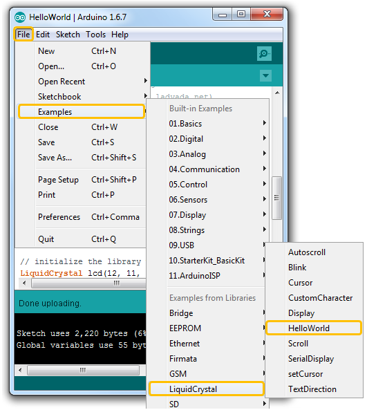
You may not need to download any special library from LCD manufacturer. I think the default LCD library and sample sketch would work with most of the LCD of this type. I just run the following sample sketch.
The source code of the sample sketch file is as shown below. The comments in color is my comment.
// include the library code: #include <LiquidCrystal.h>
// initialize the library with the numbers of the interface pins // Each of the parameter in the lcd constructor is LiquidCrystal(rs, enable, d0, d1, d2, d3); // Arduino Pin 12 is mapped to RS pin on LCD module // Arduino Pin 11 is mapped to Enable pin on LCD module // Arduino Pin 5 is mapped to d0 pin on LCD module // Arduino Pin 4 is mapped to d1 pin on LCD module // Arduino Pin 3 is mapped to d2 pin on LCD module // Arduino Pin 2 is mapped to d3 pin on LCD module LiquidCrystal lcd(12, 11, 5, 4, 3, 2);
void setup() { // set up the LCD's number of columns and rows: // This indicates that the LCD module has 16 columns (characters per line) and 2 lines lcd.begin(16, 2);
// Print a message to the LCD. lcd.print("hello, world!"); }
void loop() { // set the cursor to column 0, line 1 // (note: line 1 is the second row, since counting begins with 0): // The setCursor() is defined as void LiquidCrystal::setCursor(uint8_t col, uint8_t row). // This means set the cursor at line 1 (the second line) and column 0 (the first character) lcd.setCursor(0, 1); // print the number of seconds since reset: lcd.print(millis() / 1000); }
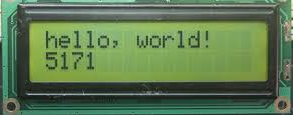
You should see something like follows when you run the sketch. I hope you can get this at the first trial :)
Understanding PINs
Once you got the first example working, you may want to read a little bit of the details of the PIN description. Strangely .. in many engineering things .. we don't usually read any document before we try .. we start reading only when we have any problem while trying.. or after making a couple things working in order to get deeper understanding. The minimum details that you need to know about this module is pin description as below.
Commonly Used Command Code
In the first example code, you don't need to care of this.. just calling a couple of function is enough. However, if you want to do some special things in addition to just to print out any text, you would need to understand the following commands. These commands are defined in LiquidCrystal.h in the library folder.
I don't think these short description would make clear sense to you. Don't get disappointed if you don't understand what these command really mean. The best practice in engineering is just to try it.
How ? Change the loop() part of the example as follows and see what's happening on the LCD and change the commands and figure out what it really does.
void loop() {
lcd.command(0x0E); delay(3000);
lcd.command(0x08); delay(3000); }
If you want to get some nicely made example of using these command rather than random 'try and see'. Look into the source code LiquidCrystal.cpp in the library folder and check the functions calling 'command()' function. For example, take a look at noblink(), blink() function.
If you want to change PIN mapping
If you would use LCD display only on your Arduino board, there wouldn't be any reason to change the pin connection from the example shown above. But if you want to add some other modules to the board and use it in combination with the LCD, you may want to change the pin connection to the LCD pin. There would be a couple of different modification for pin mapping and the control pin as follows. i) The pin on LCD is same as the example shown above and only the pin on Arduino board would change ii) The pin on LCD are same as the example show above and control R/W from Arduino program iii) You want to use all the d0~d7 pins, RS and Enable pin. iv) You want to use all the d0~d7 pins, RS, Enable and R/W pin Depending on which case you would take, you need to use different parameter settings when you create lcd object in your Arduino code. If you look into LiquidCrystal.cpp in the library folder, you would find following four different constructors. You have to chose one of these contstructors properly depending on your requirement listed above. For example, if your requirement is case i), use (D). If your requirement is case ii), use (C). If the case is iii), use (A) and if the case is iv), use (B).
(A) LiquidCrystal(uint8_t rs, uint8_t enable, uint8_t d0, uint8_t d1, uint8_t d2, uint8_t d3, uint8_t d4, uint8_t d5, uint8_t d6, uint8_t d7);
(B) LiquidCrystal(uint8_t rs, uint8_t rw, uint8_t enable, uint8_t d0, uint8_t d1, uint8_t d2, uint8_t d3, uint8_t d4, uint8_t d5, uint8_t d6, uint8_t d7);
(C) LiquidCrystal(uint8_t rs, uint8_t rw, uint8_t enable, uint8_t d0, uint8_t d1, uint8_t d2, uint8_t d3);
(D) LiquidCrystal(uint8_t rs, uint8_t enable, uint8_t d0, uint8_t d1, uint8_t d2, uint8_t d3);
What is the next step ?
Even though wiring between Arduino and LCD is pretty complicated, the programing is pretty simple if you use Arduino library. However, I would suggest you to dig further details on how LCD library works at low layer. The best way to dig into these details is to look into the library source code LiquidCrystal.cpp in the library folder and analyze all the APIs definged in the source code.
Reference :
[2] How 16×2 LCDs work | Build a basic 16×2 character LCD [3] A Note on Character LCD Displays [4] How to check whether 16x2 LCD Working or Not
|
|||||||||||||||||||||||||||||||||||||||||||||||||||||||||||


