|
Embedded System - Arduino |
||
|
Gyroscope
In this tutorial, I will show you an example of utilizing a Gyroscope. Actually this tutorial is double purposed. One is to provide you an example of Gyroscope and the other one is to show an example of I2C. Because of this double purposed tutorial, I purchased the Gyroscope supporting I2C. It is pretty expensive sense module :). The wiring of the sensor module to Arduino Uno board is as follows.
You can get the information of this device in the following web site. However, one thing that shocked me is that I don't find any detailed documents about the module except what you see in the front page and one page of schematics. I spent pretty long time to figure out the connection shown above. I was very nervous if I would blow up the sensor or Arduino board itself by connecting it in wrong way. I hope the manufacturer post more detailed documents when you are visiting this page. (However, I always recommend you to visit the web site of the module manufacturere and check if you can get the details information about the module. In some case, you may get in trouble after you buy it if you don't get the detailed information anywhere).
https://www.osepp.com/electronic-modules/sensor-modules/61-gyroscope-sensor-module
What is Slave Address for this module ?
When you buy any I2C device, make it sure that you know the slave address assigned to the device. In many case, the address is programmable and they may not write down the address information in the document or package. If you don't know of the address, you may have to spend a lot of time and effort to figure it out yourself or program the address on your own. This can be a very tedius job at the initial phase. In case of the module that I am using in this tutorial, I found the address information printed on the package of the module as below.
Where to get the library and Sample program ?
I2C is a kind of common standard. So theorectically, you can program this module with Arduino Standard I2C library (Wire library) only and you wouldn't need any additional library. However, it would be extremely tedius to figure out the details especially when those details are not provided by the module manufacturer. As I mentioned above, I couldn't find any detailed technical specification of this module when I visited the product home page (You may get more when you visit later). So it would be always good to try with libraries and sample program whenever it is available. Fortunately, I could get the pretty well working libray and sample code from following site.
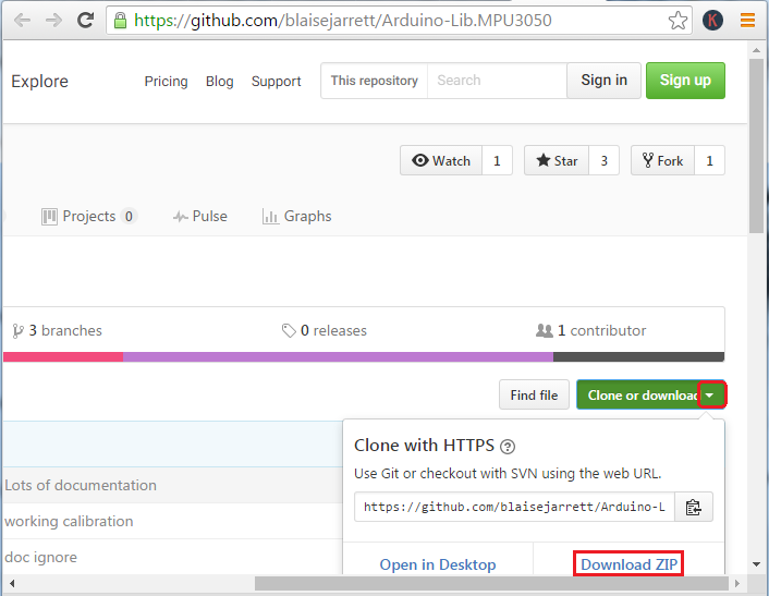
https://github.com/blaisejarrett/Arduino-Lib.MPU3050
If you unzip the downloaded package, you would get following files (I will try the sample program in Gyroscope folder)
Running a Sample Program
To run a sample program, copy the following library files (MPU3050lib.c, MPU3050lib.h) into the folder where the Arduino sample code is located. (NOTE : You can just copy these files into Arduino library folder, but I usually put them directly into the folder where the arduino sample code because the library file location tend to changes with different versions of Arduino IDE)
Open up the sketch file Gyroscope from Arduino IDE. Before you run, just read through the whole source code. You don't need to understand every details... but just take a look at it.
#include <Wire.h> // Arduino library for I2C #include "MPU3050lib.h" // Communication library that comes from the module manufacturer
Gyroscope gyro; bool fail;
void setup() { Serial.begin(9600); // This is to initialize the serial port. If you are not familiar with utilizing Arduino Serial port // refer to Serial Basic tutorial.
// set the I2C address of the gyroscope // // With the OSEPP Accelerometer use: // OSEPP_GYRO_SW_ON - Switch is in the ON position // OSEPP_GYRO_SW_OFF - Switch is in the OFF position // // begin will return 0 on success if (gyro.begin(OSEPP_GYRO_SW_ON) != 0) { Serial.println("Error connecting to gyroscope"); fail = true; return; }
// set the range // // Range // +-250 deg/s MPU3050_RANGE_PM250 // +-500 deg/s MPU3050_RANGE_PM500 // +-1000 deg/s MPU3050_RANGE_PM1000 // +-2000 deg/s MPU3050_RANGE_PM2000 gyro.setRange(MPU3050_RANGE_PM2000); }
void loop() { // don't bother reading if we failed to connect if (fail) return;
// 3 doubles to store the data double x, y, z;
// Read degrees per second // Note: You can also read the raw data by calling // readRaw() - readRaw takes int16_t instead of doubles if (gyro.readDegPerSecond(&x, &y, &z) != 0) { Serial.println("Failed to read gyroscope"); return; }
// print them out Serial.print("X: "); Serial.print(x); Serial.print(" Y: "); Serial.print(y); Serial.print(" Z: "); Serial.println(z);
delay(500); }
If you run this program and open up Arduino COM port monitor, you would see the sensor values are printed twice in a second as shown below. Rotate the sensor in various directions and see if the printed values would changes as well.
What is the next step ?
What I want to recommend you as next step are
|
||