|
|
|||||||||||||||||||||||||||||||||||||||||||
|
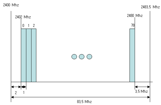
Bluetooth - Frame StructureAny kind of wireless communication,the first step to understand the underlying mechanism is to understand physical layer frame structure and the modulation scheme. I will do the same approach for bluetooth as well. Frequency Hopping in Real CommunicationBluetooth physical data occupies 1 Mhz RF bandwidth, but realy frequency range required for bluetooth communication is over 80 Mhz. Why ? It is because the sender and reciever changes its communication channel (frequency) for every frame within the range of around 80 Mhz. This way of changing frequency for each transmission is called "frequency hopping". Overall frequency allocation of each channel is as follows.
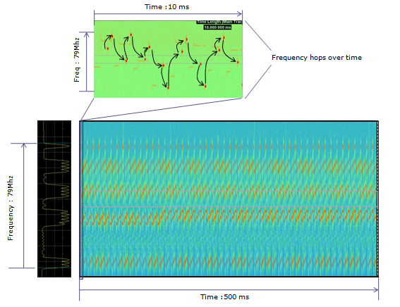
To give you some realistic view of how the frequency hopping goes, I captured the real bluetooth communication signal with signal analyzer. (It is hard to capture this kind of picture with normal analog spectrum analyzer, you have to use vector spectrum analyzer. But even with vector spectrum analyzer, it would not be easy to get the equipment to capture the full hopping range. You would need vector spectrum analyzer with at least 80 Mhz bandwidth)
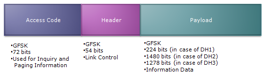
Frame StructureNow let's look into the basic transmission unit in time domain (Slot or Frame structure). A Bluetooth slot is made up of three major components (Access Code, Header and Payload) as shown below. The fundamental length of the slot is 366 us and depending on the length of Payload, it can extend to 1.622 ms or 2.87 ms. Access Code and Header is modulated always in GFSK and Payload part is modulated in one of three different methods (GFSK, 1/4pi DQPSK, 8DPSK) depending on packet type. Following is the frame structure for the most conventional bluetooth slot structure. Maximum data rate you can achieve with this structure is 1 Mbps and this stuctures uses GFSK modulation scheme across the whole slot.
Following is the frame structure for high data rate bluetooth slot structure. With this stucture, you can achieve max 2 Mhz or 3 Mhz depending on the modulation scheme of payload. The Access Code and Header part is still using GFSK modulation scheme and the payload part is using 1/4pi DQPSK for 2 Mbps data rate and 8 DPSK for 3 Mbps. You would see two additional portions in this structure comparing to previous one. First additional component is 'Guardtime'. In this structure, Access Code and Header part is using GFSK but Payload part is using DQPSK/8DPSK. It means that modulation scheme changes within a slot. This guardtime is for giving the transmitter some time to switch the modulation scheme. Another additional component is 'Sync' portion. In any I/Q based modulation, sampling timing is very imporant. 'Sync' is the portion of reference signal so that the reciever can get proper timing reference.
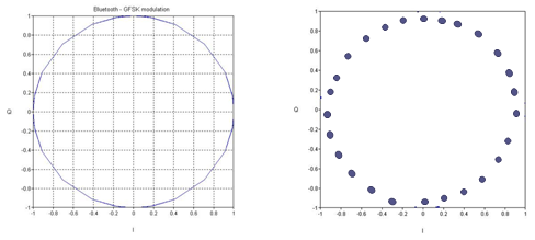
ModulationAs you read previous section about slot structure, you may noticed three different modulation schemes being used in bluetooth slot. I will give a snapshot of these three different modulation scheme in this section. I think just typical constellation for each case would be good enough for the big picture. First one is for GFSK modulation and in I/Q coordinate you would see a lot of dots sitting around the perimetor of a circle.
Following is a sample constellation for 1/4pi DQPSK. If you see the constellation on right right side, it looks exactly same as 8 PSK, but if you display the trajectory of the dots you would notice, none of the path goes through (0,0) points. This is good for amplifier effieciency and battery consumption as well. In normal QPSK case, the absolute coordinate of each dot carries the information, but in DQPSK the phase difference (angle difference) between two consecutive dots are carrying the information.
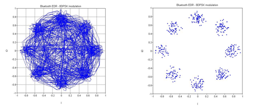
Following is a sample constellation for 1/4pi DQPSK. If you see the constellation on right right side, it looks exactly same as 8 PSK and also same as 1/4 DQPSK, but if you display the trajectory of the dots you would notice different pattern from 1/4 DQPSK. But in this case, it would be almost impossible to find the difference between 8PSK and 8 DPSK just by looking at the constellation.
|
|||||||||||||||||||||||||||||||||||||||||||