Microwave backhaul refers to using microwave radio links to transport network traffic from cell towers to the core network or between cell towers.
- What is backhaul ?
- Pros and Cons
- How widely Wireless Backhaul is adopted ?
- Frequency Spectrum
- Data Rate
- Why so many microwave antenna on tower ?
- What is inside ? (Inside of the radome ?)
- Does the size of the antenna mean anything ?
What is backhaul ?
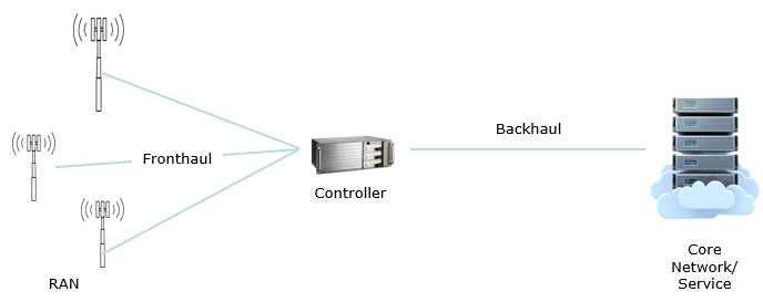
The definition of Backhaul is sometime vague but I think the most widely accepted definition can be illustrated as below. In this illustration, there is separation between backhaul and fronthaul. In some cases like 5G where the controller is splitted between CU and DU. The connection between CU and DU is often called as a midhaul. In many cases, optical fibers are used for these connection (fronthaul, backhaul, midhaul). However, in even more cases (over 50% of cases according to various reports) these connections are implemented wirelessly. In terms of performance and communication stability, I think wired backhaul is better but the wired backhaul would cause too much cost. Reducing the cost would be the strongest motivation for wirless backhaul.
When I say 'Wireless backhaul' in this note, it would include all of these connections i.e, fronthaul, backhaul, midhaul.
When the wireless backhaul is used, you would see the backhaul antenna (the round shaped antenna) at the cell site as shown below.
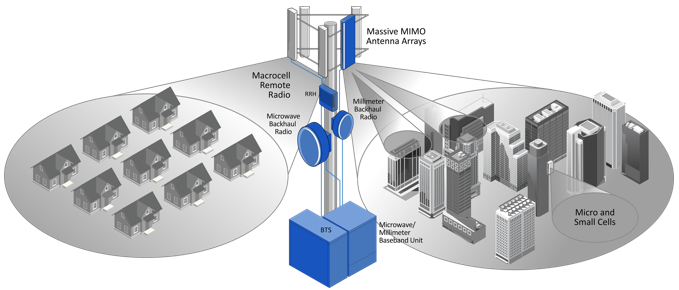
Source : MaxLinear
Source : Texas CellNet
Pros and Cons
I think most common technology (or physical medium) to implement the backhaul are optical fibers and wireless (RF or microwave). Pros and Cons of Wireless method in comparison with optical fibers can be listed as follows :
Rapid deployment - Microwave links can be installed and operational in days or weeks, much faster than laying fiber optic cables. This enables quick rollout of new cell sites.Lower costs - Microwave equipment and installation costs much less compared to fiber backhaul. This makes it economical for rural and low-density sites.-
Scalable capacity - Modern microwave backhaul can support gigabit speeds. Capacity can be increased incrementally by adding radios. -
Line-of-sight propagation - if line of sight can be allowed, it can be an advantage. Having line-of-sight enables long range backhaul links without the need to bury fiber cables or install lots of intermediate gear. Microwaves travel in straight lines allowing long range backhaul links of up to 50 km. -
Uses licensed microwave bands - Dedicated spectrum means no interference from other systems.
-
Line-of-sight requirement - Towers need to be in direct view of each other. Tower locations may be constrained. (NOTE : Not all wireless backhaul requres line of sight. If the backhaul uses lower frequency (e.g, RF ranges), it may not require line of sight. But usually those lower frequency backhaul would not support high data rate. So in most case, wireless backhaul uses high frequency region that require line of sight) -
Limited capacity - Hundreds of Mbps to 1 Gbps range. Not suitable for very high density networks. -
Weather impacts - Heavy rain or snow can attenuate signals and disrupt connectivity. Requires 99.99% availability links as backup. -
Interference potential - Microwave links can interfere with other links and cause degradation. Frequency coordination is required. -
Security concerns - Wireless transmission can be intercepted if not encrypted properly. -
Line-of-sight challenges - New buildings, trees growing can block line-of-sight over time. Links need to be monitored.
How widely Wireless Backhaul is adopted ?
Wireless backhaul adoption varies a little bit depending on Macro or Small cell application. They are slighly different but I see overall trend looks very similar to me.
Macro Backhaul
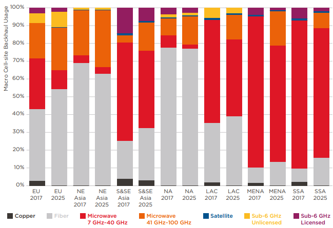
Microwave remains a viable and widely used technology for macrocell backhaul, especially in rural areas, but fiber optics is steadily gaining share to meet growing LTE capacity demands. Microwave retains advantages in cost and distance over fiber.
< Macro Backhaul by Method : Regional Markets, 2017 and 2025 >
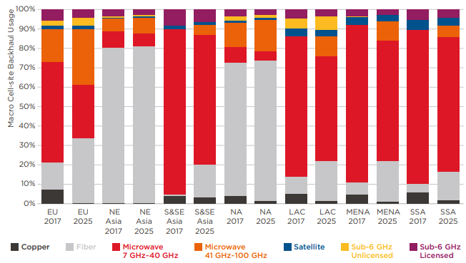
Source : ABI Research / GSMA - Mobile backhaul options : Spectrum analysis and recommendations
EU : Europe
NE Asia : North East Asia
S&SE Asia : Sourth and South East Asia
NA : North America
LAC : Latin America and Caribbean
MENA : Middle East and North Africa
SSA : Sub-Saharan Africa
Followings are summary of the trends described in Mobile backhaul options : Spectrum analysis and recommendations .
- Macrocell microwave backhaul in the 7-40 GHz bands still makes up the majority of all macrocell backhaul links worldwide. This share is declining slowly as fiber optics grows.
- Fiber optics has seen robust growth, making up the majority of macrocell backhaul links globally
- Copper xDSL links have declined rapidly, from 4% in 2017 to almost zero, as they cannot support enough data rate for modern application like 4G or 5G.
- Microwave in the 40-100 GHz millimeter wave bands is growing for macrocells as it supports 25-100 Gbps speeds over short distances.
- WiFi and satellite are niche solutions for macrocell backhaul, limited by interference and cost. Together they make up only a few percent.
- The growth of fiber optics for macrocell backhaul is in line with previous forecasts. The decline of copper xDSL was faster than expected.
- Microwave retains an advantage in low cost and scalable capacity over long distances. This has enabled it to maintain a substantial macrocell backhaul market share despite the rise of fiber.
Small cell Backhaul
fiber and microwave are predominant for small cells, with fiber growing strongly but high band microwave also on the rise to meet backhaul speed and capacity needs.
< Small Cell Backhaul by Method : Regional Markets, 2017 and 2025 >
Source : ABI Research / GSMA - Mobile backhaul options : Spectrum analysis and recommendations
EU : Europe
NE Asia : North East Asia
S&SE Asia : Sourth and South East Asia
NA : North America
LAC : Latin America and Caribbean
MENA : Middle East and North Africa
SSA : Sub-Saharan Africa
Followings are summary of the trends described in Mobile backhaul options : Spectrum analysis and recommendations .
- Fiber optic backhaul is the predominant method for small cells currently, especially in urban areas with existing fiber availability. However, comprehensive fiber rollout for small cells can be costly and challenging.
- Microwave backhaul in the traditional 7-40 GHz range has been a significant option for small cells, given its ease of deployment.
- Higher microwave frequencies like E-band and V-band are growing in share for small cell backhaul as they offer higher bandwidth and data rates.
- 60 GHz millimeter wave backhaul is also becoming popular for daisy-chained small cell networks aggregated back to the core.
- Licensed and unlicensed sub-6 GHz bands are less viable for small cell backhaul due to prioritization for access services.
- Fiber optic backhaul for small cells has exceeded expectations recently as fixed telcos accelerate fiber builds.
- Microwave backhaul in 7-40 GHz and 40-100 GHz ranges remains steady and aligned with forecasts.
- Satellite backhaul maintains a small niche role for small cells.
Frequency Spectrum
There are some use case where the wireless backhaul uses under 5Ghz. This kind of low frequency would gives many benefits but the lower frequency spectrum is almost saturated already. So, as of writhing this note (Apr 2021) most of wireless backhaul operates in microwave frequency as far as I understand, but it would be likely for the spectrum to get pushed up to higher frequency in the future.
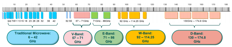
Source : GSMA Whitepaper
Data Rate
There is a wide range of throughput supported by wireless backhaul. General tendancy is that the throughput goes higher as frequency goes higher. It may be because wider spectrum is available in higher frequency as shown in the following following table from GSMA. But there are many factors affecting the throughput like modulation scheme, number of carriers, bandwidth etc. Another thing you may notice would be about Latency and Range. Considering all of these factors, it would be difficult to find the single implementation that can accomodate all the critical requirements in modern communication (i.e, high throughput, wider coverage, low latency).
< Performance Characteristics for Various Spectrum Bands >
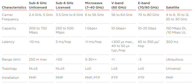
Source : ABI Research / GSMA - Mobile backhaul options : Spectrum analysis and recommendations
Why so many microwave antenna on tower ?
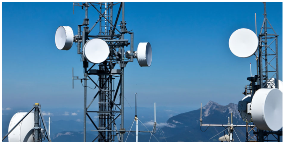
When I driving on high way, especially on rural area here in north america, I see many of huge cell towers with a lot of microwave antenna on it. It looks something this. I know the rectangular shape antenna at the top are cellular communication antenna, but I have always been wondering about the cylinder shapped antenna. I guessed they are microwave antenna for backhaul or fronthaul, but not so sure since I don't have any first hand experience with those antenna.
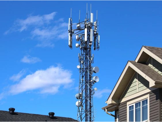
Image Source : Telecommunications towers will fill service gaps
Fortunately I had chance to talk with an expert Ashutosh Kumar in this field and learned a lot from him. My first question was why so many microwave antenna on the tower and he wrote a blog for me and kindly allowed me to share it in my note.
Microwave antennas on cell towers serve various essential purposes, which is why multiple antennas are often installed on these towers. Here are some key reasons for having multiple microwave antennas on a cell tower:
Redundancy : Redundancy is crucial in telecommunications to ensure network availability and reliability. If one antenna or link were to fail due to equipment issues or adverse weather conditions, the network can automatically switch to another antenna, minimizing service disruptions. Redundancy is especially important for critical communication services.High Capacity: With the increasing demand for data services and the growth of mobile networks, cell towers require high-capacity backhaul connections to transport large volumes of data. Multiple microwave antennas can be used to aggregate and distribute data efficiently, ensuring that the network can handle the load.Load Balancing : Multiple antennas can balance the load on the network. They allow for the distribution of data traffic from various cell sites or sectors to avoid network congestion and ensure that all users have reliable and fast connectivity.Diverse Paths : Different antennas may have different line-of-sight paths. This diversity helps mitigate interference, atmospheric conditions, or physical obstructions that can affect microwave links. Having multiple antennas with diverse paths increases the resilience of the network.Frequency Bands : Cell towers may use microwave antennas operating in different frequency bands. Different bands can accommodate various data rates and services. For example, higher-frequency bands (e.g., E-band) might be used for high-capacity, short-distance links, while lower-frequency bands might be used for longer-distance connections.Network Expansion : As cellular networks expand to cover larger geographic areas and serve more users, additional microwave antennas are installed to extend the network's reach. These antennas are positioned strategically to provide coverage where it's needed.Latency Optimization : Multiple antennas can help reduce network latency. By selecting the most appropriate microwave link for a specific data flow, network operators can optimize the transmission path to minimize delays, which is particularly important for real-time applications.To support multiple carriers :Cell towers are often shared by multiple cellular carriers. This is because it is more cost-efficient for carriers to share towers than to build their own towers. Each carrier needs its own set of antennas to transmit and receive signals from its customers' devices. This is because each carrier uses its own unique frequency spectrum.To support multiple frequency bands :Cell carriers use a variety of frequency bands to provide service to their customers. This is because different frequency bands have different characteristics. For example, some frequency bands are better suited for long-range coverage, while others are better suited for high-speed data transmission. Each frequency band requires its own set of antennas. This is because the antennas need to be tuned to the specific frequency band that they are operating on.To support multiple frequency bands :Cell carriers use a variety of frequency bands to provide service to their customers. This is because different frequency bands have different characteristics. For example, some frequency bands are better suited for long-range coverage, while others are better suited for high-speed data transmission. Each frequency band requires its own set of antennas. This is because the antennas need to be tuned to the specific frequency band that they are operating on.To connect to the core network :Cell towers also have microwave antennas to connect to the core network. The core network is the central network that manages all of the traffic on a cellular network. The microwave antennas allow the cell towers to transmit and receive data from the core network. This data includes voice calls, text messages, and internet traffic.
What is inside ? (Inside of the radome ?)
If you talk a look at the cell towers, you may find a lot of drum like structures as shown below. Those drum shapped structure is a kind of protection case for the real microwave antenna in it. The flat (usually white) cover over the antenna is known as a radome, which protects the antenna from the elements while also minimizing the drag caused by wind. Radomes are made from materials that are transparent to microwaves, allowing signals to pass through with minimal interference
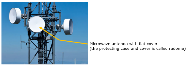
Image Source : Texas CellNet
Within the protective case is real antenna looking like below. It is a dish antenna with feedhorn. The dish acts as a reflector, which means it collects and focuses signals onto the feedhorn, which then transmits these signals to the receiver located inside it. The sizes mentioned (0.3, 0.6, 0.9, 1.0, 1.2, 1.8, 2.4, 3.0, 3.6 meters) refer to the diameter of the dish and indicate the variety of sizes that dishes can come in, which correlates to the antenna's gain and the strength of the signal it can receive or transmit.
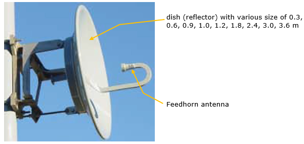
Image Source : TELECOMPONENTS
Does the size of the antenna mean anything ?
Next question popping up in my mind was why the size of those antenna varies so widely. Some of them were very small and some of them are pretty large. I vaguely guessed it may be related to the frequency based on common knoweldge on relasionship between RF/Microwave component and frequency. According the answer from Ashutosh Kumar , there seems to be more than just frequency factors.
This is also from Kumar's blog with the approval to share in this note.
The sizes of microwave antennas can vary depending on their specific design and application, but I can provide a general idea of the typical sizes for microwave dish antennas based on the provided diameters (in meters):
0.3 meters (30 centimeters) : A microwave dish antenna with a diameter of 0.3 meters (30 centimeters) would typically be a compact and relatively small antenna. These smaller dish antennas are often used for point-to-point links over shorter distances, such as for Wi-Fi or some short-range microwave communication.0.6 meters (60 centimeters) : A 0.6-meter dish antenna is larger than the 0.3-meter antenna but is still considered a relatively small dish. It may be used for point-to-point microwave links with moderate capacity and relatively short distances.0.9 meters (90 centimeters) : A 0.9-meter dish antenna is larger and provides higher gain. It can be used for longer-range point-to-point microwave links, including backhaul connections in wireless networks.1.0 meter (100 centimeters) : A 1.0-meter dish antenna is a relatively common size for microwave backhaul links, especially for medium-range connections.1.2 meters (120 centimeters) : A 1.2-meter dish antenna is larger and provides higher gain, making it suitable for longer-distance microwave links or links requiring higher capacity.1.8 meters (180 centimeters) : A 1.8-meter dish antenna is a larger antenna and is often used for medium- to long-range microwave links with high capacity.2.4 meters (240 centimeters) : A 2.4-meter dish antenna is even larger and is used for longer-range microwave links, such as backhaul connections for cellular networks or point-to-point connections between network nodes.3.0 meters (300 centimeters) : A 3.0-meter dish antenna is quite large and is used for long-distance microwave links, such as those spanning many kilometers.3.6 meters (360 centimeters) : A 3.6-meter dish antenna is even larger and is typically used for very long-distance, high-capacity microwave links or for specialized applications.
Comments from Claude.
The size of the microwave antenna used for cellular backhaul generally relates to the frequency band and capacity of the microwave link. microwave antenna size correlates with the frequency band, link capacity and distance requirements. Larger dishes support longer links but higher frequencies need smaller dishes to achieve multi-gigabit backhaul speeds.
Some key points:
- Lower frequency microwave bands like 6-11 GHz use larger dish antennas, typically 0.6 m to 1.2 meters. These provide narrower bandwidth but longer range links.
- Higher frequency bands like 18-40 GHz use smaller dishes from 0.3 m to 0.6 m. These can support more bandwidth but over shorter distances.
- Very high bands like 70-80 GHz (E-band) use tiny dishes less than 0.3m. These can provide gigabit speeds but over line-of-sight distances under 5 km.
- To increase capacity, multiple smaller dishes can be stacked together into one antenna assembly. This allows combining multiple microwave channels.
- Larger dish sizes generally provide higher antenna gain, which improves signal quality. But larger dishes have more wind loading concerns.
- On towers, larger microwave dishes may need stronger/larger mounting hardware and waveguide infrastructure. This increases cost and tower loading.
- For a given frequency band, larger dish sizes allow longer link distances or ability to use lower-cost, lower power microwave radios.
It seems that Claude comments on this mostly based on wavelength and physical component, but considering the gain of the antenna, size does not always associated only with frequency only.
A comment from Kumar : different size of anteena we can use based on distace and every single antenna make based on desire frequency ,for example if we have 0.3 antenna size it can be for any frequency 7Ghz or 10ghz or 15ghz any one
Comments from chatGPT Pro
The size of antennas, including those used in microwave communications and cellular networks, can influence various aspects of the signal transmission and reception. In practice, the design of antennas for microwave and cellular communication is a complex task that involves balancing many different factors, including the size of the antenna, to achieve the desired performance and compliance with regulatory requirements.
Here are some of the ways in which the size of a microwave antenna on a cell tower might be significant:
- Frequency Range:The size of an antenna is often related to the wavelength of the frequency it's designed to operate with. Generally, antennas are more efficient when their size is a significant fraction of the wavelength they are intended to transmit or receive. For microwave and cellular communications, the antenna size can be tailored to work optimally within specific frequency bands.
- Gain:Antenna gain is a measure of how well an antenna can transmit or receive signals in a particular direction. Larger antennas often have higher gain, meaning they can transmit signals more effectively over longer distances or with less power.
- Directivity:Larger antennas often have more directivity, meaning they can focus the signal in a more narrow beam. This can be advantageous for point-to-point microwave links or for cellular networks that need to cover a specific area without interference to or from other nearby networks.
- Beamwidth:The beamwidth of an antenna is the angle over which the antenna transmits or receives signals with relatively high gain. Larger antennas typically have narrower beamwidths, which can be advantageous in reducing interference and improving signal quality.
- Coverage:In cellular networks, the size and design of antennas can impact the coverage area. Larger antennas or antenna arrays can help improve network coverage, although other factors like antenna height and the surrounding environment also play significant roles.
- Physical Durability:Larger antennas may be constructed to withstand harsher environmental conditions such as high winds or ice loading. Their physical robustness might be necessary for reliable operation in some geographic locations.
- Appearance and Regulations:The size of antennas on cell towers can also have implications for visual impact and regulatory compliance. Larger antennas might be more visible and could be subject to different zoning or permitting requirements.
YouTube
- RCR Wireless Editorial Webinar: Microwave Backhaul for LTE, HetNet, and Small Cell Networks (Jul 2013)
- CommScope Backhaul Microwave Solutions (Jan 2014)
- Taking a peek at a microwave backhaul site (Feb 2015)
- Webinar: Mimosa Backhaul (Feb 2015)
- Defining Backhaul with Jaime Fink. Part One: Overview (Mar 2015)
- Understanding Cellular Backhaul: Microwave, on air, fibre and E1/T1 links (Nov 2015)
- 5G Backhaul: Challenges and New Architectures - Webinar Replay (Jun 2016)
- 5G Microwave Backhaul explained by Richard Jin / Better Connected with Huawei MWC18 (Apr 2018)
- Huawei Launches 5G Microwave, Paving the Way for 5G Mobile Backhaul (Aug 2018)
- The key role of microwave in 5G transport (Sep 2018)
- RAy Microwave link | RACOM (Aug 2019)
- 5G wireless backhaul provided by TU/e spin-off MaxWaves (Oct 2019)
- RAy Technical presentation (Sep 2020)
- Microwave Transmission Basics of Mobile Communication(Jul 2020)
- Day 3 | Showcase 1: MW & mmW spectrum for 5G wireless backhaul, hosted by ETSI (Aug 2020)
- Advanced 5G mmWave backhaul (Sep 2020)
- Why is wireless backhaul vital to 5G transitions? (Apr 2021)
Reference
- The Evolution of Cellular Backhaul Technologies: Current Issues and Future Trends(IEEE COMMUNICATIONS,2011)
- RSPG Report on Spectrum issues on Wireless Backhaul (Jun 2015)
- 5G Backhaul: Requirements, Challenges, and Emerging Technologies (2017)
- Mobile backhaul options : Spectrum analysis and recommendations (GSMA, Sep 2018)
- What You Need to Know About 5G Wireless Backhaul
- Mobile Backhaul (GSMA, 2019)
- Wireless Backhaul Evolution (GSMA, 2021)
- Telecom Topic Discussion by Ashutosh Kumar
- Fundamental Physics/Channel Characteristics of Microwave Link - LinkedIn post by Ashutosh Kumar
- Microwave Antenna Alignment - microwave-link.com
- Microwave Technology - CableFree
- Fresnel Zone Planning - CableFree
- Licensed Microwave Links - CableFree
- How are antennas and cellular towers different? - Quora