Voltage Divider
What is Voltage Divider ?
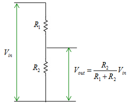
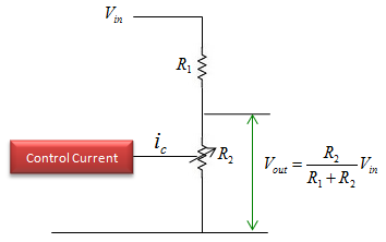
As the name implies, Voltage Divider is a type of circuit which divide (split) a one voltage level into two or more smaller voltages. The principle is based on what you learned on high school physics course. Simplest form of Voltage divider circuit is as shown below. The input voltage (Vin) is divided into two parts, one accorss R1 and the other one across R2. In most case, we are more interested in the voltage across the R2 and use this as the output (Vout) of the divider circuit.
The voltage accorss the R2 is calculated by the formula shown below which is very simple. By properly changing the value of R1 and R2, you can take any portions of Vin as Vout. For example, you can take out only 10% of Vin across R2(Vout). or 20% or 30% .. whatever you like.
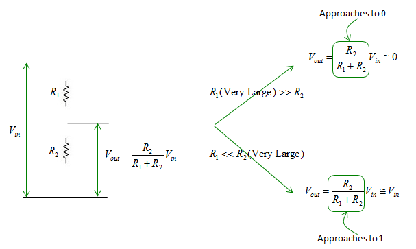
In most of the application, the difference between R1 and R2 is not so huge. (There IS difference.. but I mean the differences are not extremely huge). But in some application, we use the case where one of the register value (R1 or R2) are extremly larger than the other one (For example, R1 = 10 Ohm, R2 = 1 Mega Ohm). The property of these extreme case are summarized as below.
- When R1 is extremly larger than R2 (e.g, R1 = 1 Mega Ohm, R2 = 1 Ohm), Vout gets to be practically zero.
- When R2 is extremly larger than R1 (e.g, R1 = 1 Ohm, R2 = 1 Mega Ohm), Vout gets to be practically same as Vin
Next Step
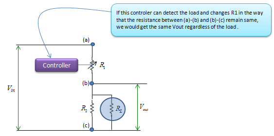
Let's think about very special (a kind of imaginary) case of Voltage Divider. What if we have a very special variable register (in stead of fixed register) and the value of variable register can be set by putting in a small control current (or control voltage) ?
Just imagine what you can do with this kind of variable register in the voltage divider.
Next question is .. 'does this kind of variable register really exists ?'. Yes.. it is called 'Transister'. Transister will be posted in a separate page.
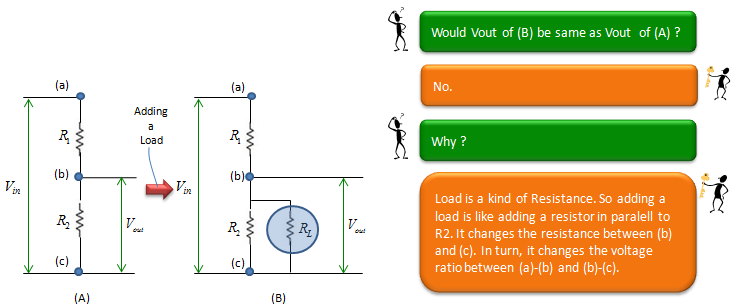
Impact of a Load