Circuit analysis is one of the places where a matrix equation appears naturally. A circuit with several loops gives one equation per loop, and neighbouring equations share unknown currents. So the loop equations form a set of simultaneous equations, and a matrix can hold all of them in one line. This page builds that matrix for a three-loop circuit, step by step, and then checks the result with numbers.
- What circuit is being solved ?
- How is KVL written for each loop ?
- How do the loop equations become a matrix equation ?
- Are the signs of the source terms right ?
What circuit is being solved ?
Let's start with the circuit and the names of its unknowns. The method on this page is mesh analysis. Each loop gets its own loop current, and these loop currents become the unknowns of the matrix equation.
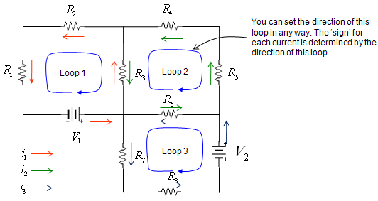
The circuit above has eight resistors, R1 to R8, and two voltage sources, V1 and V2. It is split into three loops. Each loop has its own loop current: i1 in red, i2 in green and i3 in blue. The small arrows next to each element show the direction in which that loop current is counted.
- Loop 1 contains R1, R2, R3 and V1. Loop 2 contains R3, R4, R5 and R6. Loop 3 contains R6, R7, R8 and V2.
- R3 belongs to both Loop 1 and Loop 2, and R6 belongs to both Loop 2 and Loop 3. These two shared resistors couple the equations.
- The colored arrows show i1, i2 and i3 all circulating counterclockwise. The blue arrows inside the loops set the direction for writing the equations, and they point clockwise. The note at the upper right says that this direction can be chosen freely.
- V1 has its + terminal on the right, so it pushes i1 in the direction of the red arrows. V2 has its + terminal at the top, so it pushes i3 in the direction of the blue arrows.
Three loops give three unknowns : the loop currents i1, i2 and i3 are enough to find the current in every resistor.A shared resistor carries the difference of two loop currents : R3 carries i1 - i2, and R6 carries i2 - i3.
How is KVL written for each loop ?
Kirchhoff's Voltage Law, KVL, says that the voltages around any closed loop add up to zero. Let's apply it to each loop in turn. The only care needed is the sign of each term, and the notes in the diagram below explain where each sign comes from.
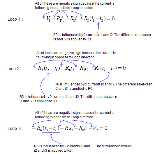
Each equation walks once around its loop in the loop direction. A resistor adds a term of R x current. The loop current is counted against the loop direction, so every such term gets a minus sign. For a shared resistor, the term uses the difference of two loop currents. In Loop 1, for example, R3 carries i1 upward and i2 downward, so its term is R3(i1 - i2).
Loop 2 has no source, so its equation contains only resistor terms. It has two shared resistors, R3 and R6, so it is the only equation that contains all three currents. Loop 1 does not contain i3, and Loop 3 does not contain i1. These missing terms become the two zeros in the matrix.
The curved arrows in the diagram also point at -V1 and -V2. A source term, however, gets its sign from the polarity of the source, not from the direction of the current. The last section of this page checks those two signs.
One KVL equation per loop : three loops give three equations for the three unknown loop currents.Consistency matters more than direction : any loop direction works, as long as every term in one equation uses the same direction.A loop equation contains only its own current and its neighbours' currents : a loop that shares no resistor with another loop has no term for that loop's current.
How do the loop equations become a matrix equation ?
The three loop equations are complete, but a matrix cannot hold them in this form yet. Each equation has to be rearranged. The unknown currents go to the left side, grouped by current, and the known source voltages go to the right side.
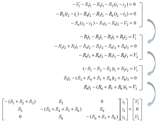
The diagram above does this in three steps. First, the brackets are expanded, and V1 and V2 move to the right-hand side. Second, the terms with the same current are collected, for example -R1i1 - R2i1 - R3i1 = -(R1 + R2 + R3)i1. Third, the coefficients of i1, i2 and i3 in each equation become one row of the matrix.
You can read the finished matrix directly from the circuit. Diagonal element (n, n) is minus the sum of all resistors in loop n. Off-diagonal element (m, n) is the resistor shared by loops m and n, and it is 0 when the two loops share nothing. So the matrix is symmetric. R3 appears at (1, 2) and (2, 1), and R6 appears at (2, 3) and (3, 2).
The negative diagonal comes from the loop direction chosen in the drawing. Multiplying every row by -1 gives the more common textbook form, with a positive diagonal and negative shared resistors. This loop resistance matrix has the same structure as the stiffness matrices on the FEM pages of this site: positive diagonal, non-positive off-diagonal, and symmetric.
The diagonal holds the total resistance of each loop : here it carries a minus sign, because of the loop direction chosen in the drawing.The off-diagonal holds the shared resistance : two loops that share no resistor give a zero, like elements (1, 3) and (3, 1).The matrix is symmetric : a shared resistor couples both loops in the same way.
Are the signs of the source terms right ?
A numeric check is the fastest way to trust a matrix equation. Let's give every element a value, solve the matrix, and compare the result with a direct analysis of the same circuit. This check finds a sign problem in the source terms.
Take R1 to R8 = 1, 2, 3, 4, 5, 6, 7 and 8 ohm, V1 = 10 V and V2 = 5 V. A direct node-voltage analysis of the circuit gives i1 = 130/69 = 1.884 A, i2 = 10/23 = 0.435 A and i3 = 25/69 = 0.362 A. All three are positive, so the currents flow in the directions of the arrows in the circuit diagram. The matrix equation above gives the same three numbers, but with a minus sign in front of each.
The reason is the sign of V1 and V2. Walk Loop 1 in the loop direction, along the bottom wire from right to left. You enter V1 at its + terminal and leave at its - terminal, so the potential drops by V1. On the same walk, each resistor raises the potential by R x current, because you walk against the current. So the correct Loop 1 equation is V1 - R1i1 - R2i1 - R3(i1 - i2) = 0, with +V1. The same walk around Loop 3 gives +V2 in its equation.
With these two signs, the right-hand side becomes (-V1, 0, -V2), and the matrix itself does not change. Multiplying all three rows by -1 then gives the usual form below.
[ R1+R2+R3  -R3          0        ] [ i1 ]   [ V1 ]
[ -R3       R3+R4+R5+R6  -R6      ] [ i2 ] = [ 0  ]
[ 0         -R6          R6+R7+R8 ] [ i3 ]   [ V2 ]
With the example values, this matrix is [6 -3 0; -3 18 -6; 0 -6 21], and the right-hand side is (10, 0, 5). The determinant is 1863, so the solution is unique, and it matches the direct analysis. The loop currents then give every branch current. R3 carries i1 - i2 = 1.449 A upward, and R6 carries i2 - i3 = 0.072 A from left to right.
A source term takes its sign from the polarity : walking from + to - through a source is a drop, whatever the direction of the current.The equations in the diagrams flip the sign of all three currents : with -V1 and -V2, the example gives i1 = -1.884 A instead of +1.884 A.Check a matrix equation with numbers : a small circuit solved another way shows sign errors that the algebra hides.