The two spring pages before this one let each node move in one direction only. A real structure is not that simple. The joints of a truss can move in a plane, and the bars can point in any direction. This page extends the same stiffness matrix method to a plane truss with three nodes and three bars.
I got the idea of this example from IFEM.Ch01.Slides.pdf, IFEM.Ch02.Slides.pdf, IFEM.Ch03.Slides.pdf (Try google these files and will get further details).
- What truss is being analyzed ?
- Why is the stiffness matrix 6 x 6 ?
- How is each bar's stiffness matrix built ?
- How are the three bar matrices combined ?
- How are the displacements and the support forces found ?
- Where does the cos and sin pattern come from ?
What truss is being analyzed ?
Let's first fix the geometry and the names, because every number in the matrices below depends on them. The key quantities are the angle of each bar and the stiffness of each bar.
The goal in this example is to show the process to construct the stiffness matrix for a simple truss as shown at the left side of the following illustration. You can replace each bar with a spring as shown in the right side of the following illustration. Now you have very similar model to the previous example. But there is very one important difference between this example and previous example. In previous example, we assumed that each node can move only in ONE direction. x direction (horizontal direction), but in this example we give each of the nodes one more freedom. Now each node can move in any way in two dimensional plane. It means the direction of the force applied to each node can be from anywhere in the plane, but as you know wherever the direction is we can describe the force with the two component of forces (horizantal force and vertical foruce) as marked below. "f" represents the force acting on each node and "u" represents the displacement of each nodes as result of the forces acting on the node.
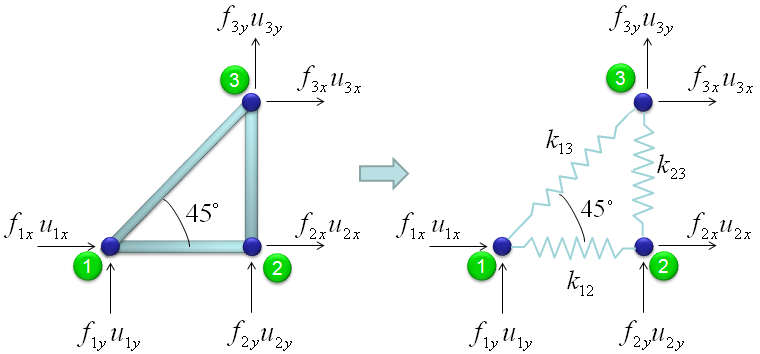
The drawing above shows the truss on the left and the equivalent spring model on the right. Node 1 is at the lower left, node 2 is at the lower right, and node 3 is directly above node 2.
- The bar from node 1 to node 2 is horizontal, and the bar from node 2 to node 3 is vertical.
- The bar from node 1 to node 3 makes a 45 degree angle with the horizontal bar. So the triangle has a right angle at node 2.
- Each bar becomes a spring k12, k23 or k13. For a bar with Young's modulus E, cross-section area A and length L, the axial stiffness is k = EA/L.
- Each node has two forces and two displacements. For example, node 1 has f1x and f1y, and u1x and u1y.
A truss bar acts as an axial spring : it resists stretching and compression along its own length, and nothing else.Each node now has two unknowns : the horizontal and the vertical displacement.
Why is the stiffness matrix 6 x 6 ?
The size of the matrix follows from counting unknowns, not nodes. The rule from the spring pages still holds: one row and one column per unknown. Here each node simply has two unknowns instead of one.
The force and stiffness matrix, displacement relationship is represented as follows and the goal in this example is to go through the steps to fill out the stiffness matrix (K matrix). You may feel a little strange because you have 6 x 6 matrix when you have only three nodes. According to the logic in previous example, you might expect that you would have 3 x 3 matrix since you have only three nodes. The reason why you have much larger matrix than the number of the nodes is that you have to describe the two directional forces for each node.
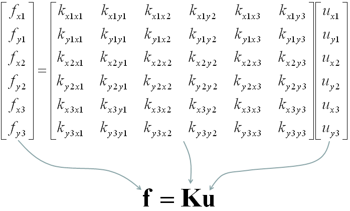
The vectors in the matrix equation above list the unknowns node by node: ux1, uy1, ux2, uy2, ux3, uy3. The force vector follows the same order. Each element of K has a clear meaning. For example, kx1y2 is the force in the x direction at node 1 when node 2 moves by one unit in the y direction and every other displacement is zero.
Because the order goes node by node, K splits into a 3 x 3 grid of 2 x 2 blocks. Block (i, j) links the two forces at node i to the two displacements at node j. You will see these blocks framed in the numeric matrices below.
Matrix size = number of nodes x number of directions : three nodes that each move in two directions give a 6 x 6 matrix.Each element links one force to one displacement : kx1y2 is the x force at node 1 caused by a unit y move of node 2.The node-by-node order creates 2 x 2 blocks : each block belongs to one pair of nodes.
How is each bar's stiffness matrix built ?
Let's take the truss apart and treat each bar on its own. Each bar gives a 6 x 6 matrix that is zero everywhere except in the rows and columns of its own two nodes. The formula is the same for every bar. Only the stiffness k and the angle θ change.
Overall procedure of realizing the matrix (stiffness matrix) is almost same as you saw in previous example.
Bar 1 - node 1 to node 2
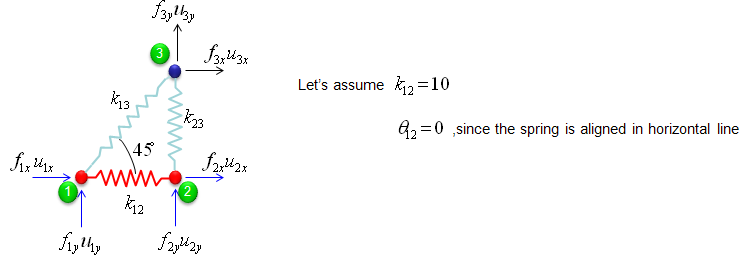
The first step is to split the whole system into each components. The first component is about the two nodes (node 1 and 2). As shown below, these two nodes are connected by single spring marked in red.
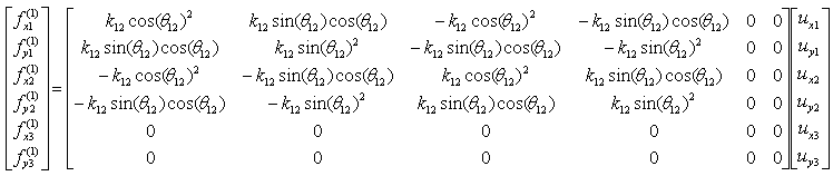
The stiffness values about this spring connecting these two nodes are described as below. (You can refer to the slides that I mentioned at the beginning to understand where these mathematical expression came from. Or just use these expressions).
If we assume k12 to be 10 and the angle of the spring from the horizontal line is 0, you can have the following expression.
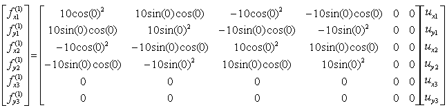
If you calculate the expressions shown above, you will have the following values.
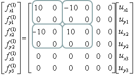
The numbers above show what a horizontal bar does. With θ12 = 0, cos = 1 and sin = 0, so only the x-x terms survive. The bar resists a difference between ux1 and ux2. It gives no resistance to vertical motion at all. The nonzero part is the 1D spring matrix of the Simple Spring page, 10 x [1 -1; -1 1], placed in the x rows and columns of node 1 and node 2.
Bar 2 - node 2 to node 3
The second component is about the two nodes (node 2 and 3). As shown below, these two nodes are connected by single spring marked in red.
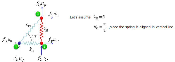
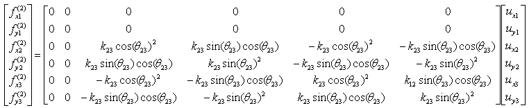
The stiffness values about this spring connecting these two nodes are described as below. (You can refer to the slides that I mentioned at the beginning to understand where these mathematical expression came from. Or just use these expressions).
If we assume k23 to be 5 and the angle of the spring from the horizontal line is 90 degree (pi/2), you can have the following expression.
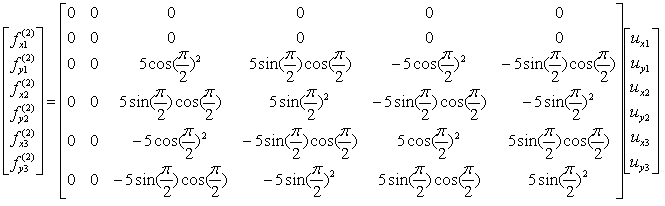
If you calculate the expressions shown above, you will have the following values.
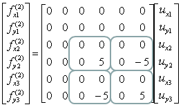
The vertical bar is the mirror case of the horizontal one. With θ23 = 90 deg, cos = 0 and sin = 1, so only the y-y terms of node 2 and node 3 remain. Notice a small error in the symbolic matrix. The element in the ux3 row and the uy3 column reads k12 sin(θ23)cos(θ23), but it should be k23. The numeric matrices use k23 = 5 there, and the term is zero anyway because cos(π/2) = 0.
Bar 3 - node 1 to node 3
The third component is about the two nodes (node 3 and 1). As shown below, these two nodes are connected by single spring marked in red.
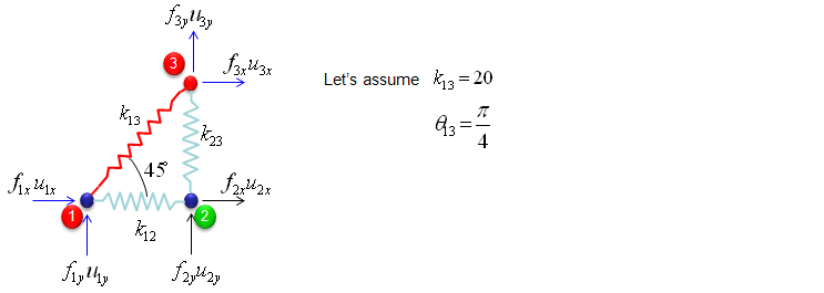
The stiffness values about this spring connecting these two nodes are described as below. (You can refer to the slides that I mentioned at the beginning to understand where these mathematical expression came from. Or just use these expressions).
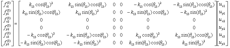
If we assume k13 to be 20 and the angle of the spring from the horizontal line is 45 degree (pi/4), you can have the following expression.
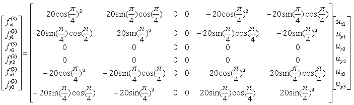
If you calculate the expressions shown above, you will have the following values.
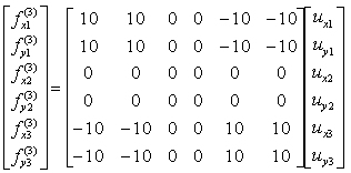
The diagonal bar is the only one that couples the x and y directions. At 45 deg, cos2 = sin2 = sin cos = 1/2, so every nonzero entry has the size k13/2 = 10. As a result, a horizontal move of node 3 also creates a vertical force at node 3 and at node 1. The symbolic matrix has two typing errors here. The uy1 row, uy1 column should read k13 sin(θ13)2, not k12, and the ux3 row, ux3 column should read cos(θ13)2, not cos(θ12)2. The numeric matrices are correct.
A bar fills only the blocks of its own two nodes : all other rows and columns of its 6 x 6 matrix are zero.The angle decides which directions are coupled : 0 deg gives only x terms, 90 deg only y terms, and 45 deg gives equal x and y terms.Every bar matrix has the pattern [B -B; -B B] : B is a 2 x 2 block, and the last section of this page derives it.
How are the three bar matrices combined ?
Each bar matrix already has the full 6 x 6 size, so combining them needs no index bookkeeping. You simply add them element by element. This is the same assembly step as on the spring pages, done here with larger matrices.
Through the three steps we have done above, you have three stiffness matrix describing each two nodes connected by each spring. The final step is to combine all of these matrix and get a single/combined stiffness matrix.
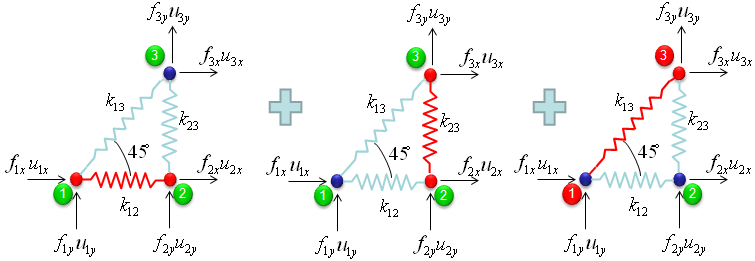
With summation of the three matrices that we got from previous steps,
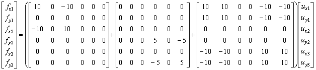
you would get the following single matrix.
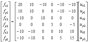
You can check a few entries of the result by hand. The entry kx1x1 = 20 is 10 from bar 1 plus 10 from bar 3, because both bars are attached to node 1. The entry ky3y3 = 15 is 5 from bar 2 plus 10 from bar 3. The entry kx2y2 is 0, because neither bar at node 2 couples the x and y directions there.
The combined K is symmetric, like every stiffness matrix on these pages. It is also singular. Its rank is 3, not 6, so three independent motions produce no force at all. These are the rigid body motions of a flat structure: a move in x, a move in y, and a small rotation. So, as on the Simple Spring page, you must fix some displacements before you can solve.
Assembly is a plain sum : the three 6 x 6 bar matrices add element by element.A diagonal entry collects every bar at that node : kx1x1 = 10 + 10 because bar 1 and bar 3 meet at node 1.A free truss has three rigid body motions : K has rank 3, so at least three displacements must be fixed.
How are the displacements and the support forces found ?
The matrix is complete, but the page stops before using it. Let's finish the job with a simple load case. The supports remove the rigid body motions, and then a small 3 x 3 system gives the displacements.
Take node 1 as a pinned support, so ux1 = uy1 = 0. Take node 2 as a roller that can move only horizontally, so uy2 = 0. These three conditions remove exactly the three rigid body motions. Apply a load at node 3 with fx3 = 2 and fy3 = 1, and no load at node 2 in the x direction.
The three free unknowns are ux2, ux3 and uy3. So keep rows and columns 3, 5 and 6 of the combined K. This gives the reduced system below.
[ 10  0   0  ]   [ ux2 ]   [ 0 ]
[ 0   10  10 ]   [ ux3 ] = [ 2 ]
[ 0   10  15 ]   [ uy3 ]   [ 1 ]
The first row gives ux2 = 0. The other two rows give ux3 = 0.4 and uy3 = -0.2. So node 3 moves to the right and down, and node 2 does not move. Multiplying the full K by the complete displacement vector then gives the support forces: fx1 = -2, fy1 = -2 and fy2 = 1. The forces balance, because -2 + 2 = 0 in x, and -2 + 1 + 1 = 0 in y.
The bar forces follow from the stretch of each bar. Bar 1 does not change length, so it carries no force. Bar 2 shortens by 0.2, so it carries a compression of 5 x 0.2 = 1. Bar 3 stretches by (0.4 - 0.2)/√2 = 0.141, so it carries a tension of 20 x 0.141 = 2.83. These are the same results that a hand calculation with the method of joints gives.
Supports turn a singular K into a solvable one : fixing ux1, uy1 and uy2 leaves a 3 x 3 system with determinant 500.The removed rows give the support forces : after the solve, f = Ku returns the reactions at the fixed displacements.Bar forces come from the stretch along each bar : here bar 1 carries 0, bar 2 carries 1 in compression, and bar 3 carries 2.83 in tension.
Where does the cos and sin pattern come from ?
The page takes the element formula from the IFEM slides without deriving it. The derivation is short, so let's do it. It uses only the fact that a bar reacts to stretching along its own axis.
Take a bar from node i to node j at angle θ, and write c = cos θ and s = sin θ. The unit vector along the bar is (c, s). The bar stretches by the part of the relative displacement that lies along this vector.
stretch      d = c(uxj - uxi) + s(uyj - uyi)
bar force    N = k d
at node j    (fxj, fyj) = N (c, s)
at node i    (fxi, fyi) = -N (c, s)
Write out fxj = kc(c uxj - c uxi + s uyj - s uyi). The coefficients are kc2 and kcs with a plus sign for node j, and with a minus sign for node i. The other three forces follow in the same way. Together they give the element matrix k[B -B; -B B], with the 2 x 2 block B = [c2 cs; cs s2]. This is exactly the pattern of cos2, sin cos and sin2 in the symbolic matrices above.
Two checks connect the formula to the rest of the page. At θ = 0, B = [1 0; 0 0], and the element matrix becomes the 1D spring matrix. Also, B has rank 1. So a bar resists only one combination of the four displacements, which is the stretch d.
A bar feels only its stretch : the stretch is the relative displacement projected onto the bar direction (c, s).The element matrix is k[B -B; -B B] : B = [c2 cs; cs s2] holds the direction of the bar.At θ = 0 the truss bar is the 1D spring : the plane truss method contains the spring pages as a special case.