Incidence Matrix is a type matrices that represents the connections between vertices and edges in a graph. The meaning of each columns and rows of the matrix can be illustrated as follows.
The adjacency matrix relates a vertex to a vertex. The incidence matrix relates a vertex to an edge instead. It has one row for each vertex and one column for each edge, so a graph with n vertices and m edges gives an n x m matrix. Because every edge has its own column, the matrix keeps the edge names, and it can also hold two edges between the same pair of vertices. I'll use the same four-vertex graph as the adjacency matrix page, first with directions and then without.
Case 1 : Directed Graph
In a directed graph, each edge leaves one vertex and enters another. So each column needs two nonzero numbers, and their signs tell the two ends apart. The drawing below uses -1 for the vertex the edge gets out of and +1 for the vertex it gets into.
The graph has the edges e1 from v1 to v3, e2 from v4 to v1, e3 from v4 to v3 and e4 from v3 to v2. The blue arrows lead from each edge to its column. The green notes on the right explain each row, and the notes under the matrix explain each column.
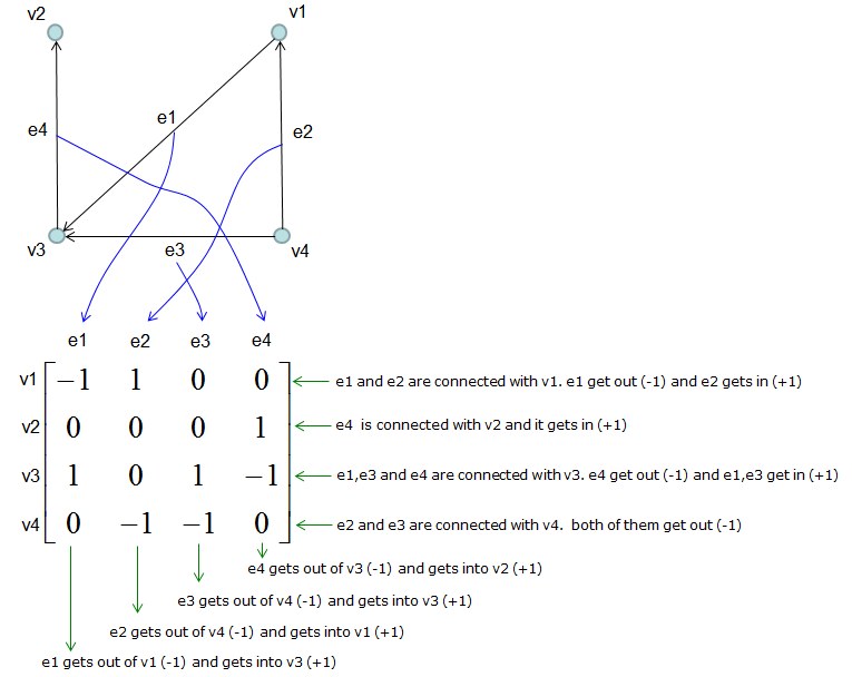
Read the matrix by columns first. Each column holds exactly one -1 and one +1, so every column sums to 0. Now read it by rows. The sum of row i is the number of edges that get into vi minus the number that get out. For v1 to v4, the row sums are 0, 1, 1 and -2. For example, v4 has two edges leaving and none arriving, so its row sum is -2.
Not every text uses the same sign convention. Many textbooks put +1 at the tail and -1 at the head, which is the negative of the matrix above. Both forms carry the same information. The products used in the last section are also the same for both forms, because the sign change cancels.
Each column describes one edge : It has -1 at the vertex the edge leaves and +1 at the vertex it enters, and 0 everywhere else.Every column sums to 0 : So the sum of all rows is the zero vector, and the rank of the matrix is at most n - 1. For this connected graph the rank is exactly 3 = 4 - 1.Row sums give in-degree minus out-degree : Here they are 0, 1, 1 and -2.The sign convention is a choice : Check which end gets +1 before you compare with another text.
Case 2 : Non-Directed Graph
This is the case for Non-Directed graph. An example is as follows. It is the graph of Case 1 with the arrow heads removed, so it has the same four edges between the same vertices.
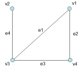
Since the sign of the number in incidence matrix is determined by the direction of the edge. You may be a little confused on how to set the sign of the number in case of Non-directed Graph. There is a simple solution for the confusion. You can think of the non-directed graph as a directed graph but all of the egdes have arrow heads on both ends. Once you convert the graph like this, you can easily construct the incidence matrix as you did in the case of directed graph as shown below.
In the drawing below, every edge has two arrow heads, so each end gets +1. The notes on the right explain each row, and the notes under the matrix explain each column.
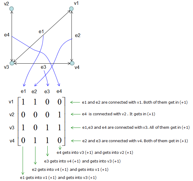
The result is the matrix of Case 1 with every -1 changed to +1. Each column now sums to 2, because each edge has two ends. The sum of row i is the degree of vi, which is 2, 1, 3 and 2 for v1 to v4. This all-positive form is called the unsigned incidence matrix. Some texts handle an undirected graph in a different way. They give every edge an arbitrary direction and use the signed matrix of Case 1. That signed form is the one needed for the Laplacian in the next section.
An undirected edge gives +1 at both ends : The matrix holds only 0 and 1 for a graph without loops.Every column sums to 2 : Each edge has exactly two ends.Row sums are the degrees : Here they are 2, 1, 3 and 2, the same as the row sums of the adjacency matrix.
Incidence Matrix and the Other Graph Matrices
The incidence matrix is rarely the final goal. It is useful because simple products of it give the other graph matrices, and because it turns flows and potentials on a network into linear algebra. Let's write B for the signed matrix of Case 1 and M for the unsigned matrix of Case 2.
The first product is B BT. The diagonal element i counts the edges that touch vi, so it is the degree. An off-diagonal element (i, j) is -1 when an edge joins vi and vj, because that edge has +1 at one end and -1 at the other. So B BT = D - A, which is the Laplacian matrix L of the undirected graph. The direction of the edges does not matter here. For the example graph, the table below gives the result.
B BT |
v1 |
v2 |
v3 |
v4 |
v1 |
2 |
0 |
-1 |
-1 |
v2 |
0 |
1 |
-1 |
0 |
v3 |
-1 |
-1 |
3 |
-1 |
v4 |
-1 |
0 |
-1 |
2 |
The unsigned matrix gives a plus sign instead, M MT = D + A. This matrix is called the signless Laplacian. The other order, MT M, is an m x m matrix over the edges. Its diagonal is 2, and its off-diagonal element is 1 when two edges share a vertex. For the example, e2 and e4 share no vertex, so that element is 0, and every other pair of edges shares one vertex.
B also has a physical meaning, which is why it appears in circuit analysis. Put a flow fk on each edge ek. Then row i of B f is the total flow into vi minus the total flow out, and B f = 0 is Kirchhoff's current law. For the example, f = (1, 1, -1, 0) satisfies B f = 0. This flow goes around the triangle v1, v3, v4 and returns to its start. In the other direction, put a potential xi on each vertex. Then BT x gives, for each edge, the potential at its head minus the potential at its tail. With x = (0, 1, 2, 3), BT x = (2, -3, -1, -1).
B BT is the Laplacian : The signed incidence matrix gives L = D - A, whichever direction each edge was given.M MT is D + A : The unsigned matrix gives the signless Laplacian.B f = 0 is Kirchhoff's current law : The flows that satisfy it go around cycles. This graph has one independent cycle, since m - rank = 4 - 3 = 1.BT x gives the potential difference across each edge : This is the step that leads to voltage drops in a circuit.