A rotation alone keeps the centre of an object in place. To move the object somewhere else, we also need a translation, and a translation cannot be written as a 3 x 3 matrix product. This page shows how one 4 x 4 homogeneous matrix does both jobs at once. The example turns a cube by 30 deg around the x axis and moves it by 1 along the x axis in a single multiplication.
- What does the transformation matrix hold ?
- What does the transformed cube look like ?
- Matlab Code
- Does the order of rotation and translation matter ?
What does the transformation matrix hold ?
This is an example of rotating and translating a 3D object (a Cube) using a Transformation Matrix in the form as shown below. The transformation matrix is applied (multiplied) to each vertex of the cube.
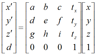
Figure 1. The general 4 x 4 transformation matrix. The 3 x 3 block a to i turns, scales or shears the vertex, and the last column tx, ty, tz moves it.
- The upper-left 3 x 3 block, a to i, is the linear part. It holds the rotation in this example, but a scaling or a shear goes in the same place.
- The fourth column, tx, ty and tz, is the translation. It is added to x', y' and z' because it multiplies the constant 1 at the bottom of the input vector.
- The fourth row is [0 0 0 1]. It keeps the fourth coordinate d equal to 1, so the output can go straight into the next 4 x 4 matrix.
The reason for the fourth coordinate is simple. Any 3 x 3 matrix A maps the zero vector to itself, because A0 = 0. So no 3 x 3 matrix can move the origin, and a translation always moves it. The extra 1 at the bottom of the vertex gives the last column something to multiply. With it, a translation becomes one more matrix product, and a chain of rotations and translations collapses into a single matrix.
In the example, φ = π/6 (30 deg), the block a to i is the rotation around x, and the translation column is (1, 0, 0). The matrix in the red part of the code is therefore:
M = [ 1   0         0        1 ]     [ 1   0         0        1 ]
    [ 0   cos(φ)   -sin(φ)    0 ]  =  [ 0   0.8660   -0.5000   0 ]
    [ 0   sin(φ)    cos(φ)    0 ]     [ 0   0.5000    0.8660   0 ]
    [ 0   0         0        1 ]     [ 0   0         0        1 ]
Let's follow one corner through it. Take the corner (0.5, 0.5, 0.5). Its new x is 0.5 + 1 = 1.5. Its new y is 0.866 x 0.5 - 0.5 x 0.5 = 0.183, and its new z is 0.5 x 0.5 + 0.866 x 0.5 = 0.683. The x coordinate only moves, because the rotation around x never changes it. The y and z coordinates only turn, because the translation has no y or z part.
One 4 x 4 matrix holds a rotation and a translation : the rotation sits in the upper-left 3 x 3 block and the translation in the last column.A translation needs the homogeneous coordinate : a 3 x 3 matrix always maps the origin to the origin, so it cannot express a shift.The last row [0 0 0 1] keeps the vertex homogeneous : the result can go directly into the next matrix of a chain.
What does the transformed cube look like ?
The flat views are the best place to separate the two effects of the matrix. A rotation around x shows up only in the view along the x axis. The shift along x shows up only in the two views that contain the x axis.
The result of this example is as shown below.
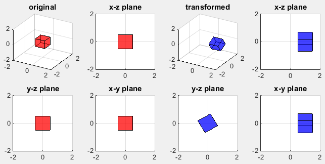
Figure 2. The cube before the transformation, in red, and after it, in blue. The blue cube is tilted by 30 deg around the x axis and its centre has moved from x = 0 to x = 1.
- The two left columns show the original cube, centred at the origin, as a 1 x 1 square in each flat view.
- In the x-z view of the blue cube, the square now spans x = 0.5 to 1.5, so its centre is at x = 1. Its height has grown to about +/-0.68, because the tilted cube shows two of its faces in this view.
- In the y-z view, the blue square is the same size as the red one but turned by 30 deg. This view looks along the rotation axis, so it shows the true rotation angle, and the shift along x is invisible.
- The x-y view matches the x-z view. The cube is shifted to x = 0.5 to 1.5 and appears about 1.37 high, again because of the tilt.
The height of +/-0.683 in the x-z and x-y views comes straight from the matrix. A corner of the unit cube is at most 0.5 from the centre along y and along z. After the rotation, its z coordinate is 0.5 sin(φ) + 0.5 cos(φ) at most, which is 0.25 + 0.433 = 0.683 for φ = 30 deg. The same value appears along y by symmetry.
The view along the rotation axis shows the true angle : the y-z view shows the 30 deg turn without distortion and hides the shift along x.The views that contain x show the translation : the centre moves from 0 to 1 in both the x-z and x-y views.A tilted cube looks wider in a flat view : the outline grows from 1 to 1.37 because two faces are visible, not because the cube is scaled.
Matlab Code
Following is the MatLab code for this example. For now, don't pay too much about the code itself, just focus on number marked in red and try to undertand the mathematical meaning intuitively. You can just copy the code here into your Matlab and change the numbers in red part until you develop the intuitive understanding.
Note : When copy and paste this code, '...' may cause some error. In that case, erase '...' and retry '...' in your matlab editor.
clear all;

vert = [-0.5 -0.5 -0.5;  ...
        -0.5 0.5 -0.5;  ...
         0.5 0.5 -0.5;  ...
         0.5 -0.5 -0.5; ...
        -0.5 -0.5 0.5; ...
         -0.5 0.5 0.5;  ...
          0.5 0.5 0.5; ...
          0.5 -0.5 0.5];

fac = [1 2 3 4; ...
    2 6 7 3; ...
    4 3 7 8; ...
    1 5 8 4; ...
    1 2 6 5; ...
    5 6 7 8];

% original object
subplot(2,4,1);
patch('Faces',fac,'Vertices',vert,'FaceColor','r');
axis([-2 2 -2 2 -2 2]);
grid();
material shiny;
alpha('color');
alphamap('rampdown');
view(30,30);
title('original');

% view along y-axis (x-z plane)
subplot(2,4,2);
patch('Faces',fac,'Vertices',vert,'FaceColor','r');
axis([-2 2 -2 2 -2 2]);
grid();
material shiny;
alpha('color');
alphamap('rampdown');
view(0,0);
title('x-z plane');

% view along x-axis (y-z plane)
subplot(2,4,5);
patch('Faces',fac,'Vertices',vert,'FaceColor','r');
axis([-2 2 -2 2 -2 2]);
grid();
material shiny;
alpha('color');
alphamap('rampdown');
view(90,0);
title('y-z plane');

% view along z-axis (x-y plane)
subplot(2,4,6);
patch('Faces',fac,'Vertices',vert,'FaceColor','r');
axis([-2 2 -2 2 -2 2]);
grid();
material shiny;
alpha('color');
alphamap('rampdown');
view(0,90);
title('x-z plane');


% transforming the object

VerticesHom = zeros(8,4);
for i = 1:8
    VerticesHom(i,:) = [vert(i,:) 1];
end

phi = pi/6;
TxMatrix = [1    0       0       1;...
            0 cos(phi) -sin(phi) 0; ...
            0 sin(phi) cos(phi)  0; ...
            0    0       0       1];
TxVerticesHom = TxMatrix * VerticesHom';
TxVerticesHom = TxVerticesHom';

TxVertices = zeros(8,3);
for i = 1:8
    TxVertices(i,:) = TxVerticesHom(i,1:3);
end

% transformed object
subplot(2,4,3);
patch('Faces',fac,'Vertices',TxVertices,'FaceColor','b');
axis([-2 2 -2 2 -2 2]);
grid();
material shiny;
alpha('color');
alphamap('rampdown');
view(30,30);
title('transformed');

% view along y-axis (x-z plane)
subplot(2,4,4);
patch('Faces',fac,'Vertices',TxVertices,'FaceColor','b');
axis([-2 2 -2 2 -2 2]);
grid();
material shiny;
alpha('color');
alphamap('rampdown');
view(0,0);
title('x-z plane');

% view along x-axis (y-z plane)
subplot(2,4,7);
patch('Faces',fac,'Vertices',TxVertices,'FaceColor','b');
axis([-2 2 -2 2 -2 2]);
grid();
material shiny;
alpha('color');
alphamap('rampdown');
view(90,0);
title('y-z plane');

% view along z-axis (x-y plane)
subplot(2,4,8);
patch('Faces',fac,'Vertices',TxVertices,'FaceColor','b');
axis([-2 2 -2 2 -2 2]);
grid();
material shiny;
alpha('color');
alphamap('rampdown');
view(0,90);
title('x-z plane');
The listing follows the same steps as the three axis rotation example. The eight corners in vert get a 1 appended, which makes the 8 x 4 matrix VerticesHom. The red lines build the single 4 x 4 matrix TxMatrix, and one product applies it to all eight corners at once. The code then drops the fourth column and draws the result. As before, VerticesHom' puts one vertex in each column, because TxMatrix acts on column vectors.
Two numbers in the red part are worth changing. The value of phi sets the rotation angle, and the 1 at the end of the first row is tx. For example, replace the 0 at the end of the third row with 1. The cube then also moves up by 1 along z, and only the x-z and y-z views show that shift.
The listing has one small labelling problem. The subplots in positions 6 and 8 use view(0,90), which looks down the z axis, but their titles say 'x-z plane'. That view is the x-y plane. The plot in Figure 2 carries the correct 'x-y plane' titles, so it was produced by a slightly different version of the code. If you run the listing as shown, read the two lower 'x-z plane' panels as x-y views.
One product transforms every vertex : TxMatrix * VerticesHom' applies the rotation and the translation to all eight corners together.The translation lives in the last column : editing the fourth entry of a row moves the cube along that axis.view(0,90) is the x-y plane : the listing titles those two panels 'x-z plane', while Figure 2 labels them correctly.
Does the order of rotation and translation matter ?
A single matrix hides the order of its two parts. The matrix of this page could mean "rotate, then move" or "move, then rotate". So let's check whether the two readings give the same cube, first for this example and then in general.
Write T for the pure translation by (1, 0, 0) and Rx for the pure rotation around x. For this example both products are equal, TRx = RxT = M. The reason is that the shift runs along the rotation axis. Rotating around x does not change a vector that points along x, so the translation survives the rotation unchanged.
This is a special case. Keep the same shift, but rotate by 30 deg around z instead. The two orders now give different matrices.
T Rz = [ 0.866  -0.5    0    1     ]        Rz T = [ 0.866  -0.5    0    0.866 ]
       [ 0.5     0.866  0    0     ]               [ 0.5     0.866  0    0.5   ]
       [ 0       0      1    0     ]               [ 0       0      1    0     ]
       [ 0       0      0    1     ]               [ 0       0      0    1     ]
The rotation blocks are the same, but the translation columns differ. TRz turns the cube in place and then moves its centre to (1, 0, 0). RzT moves the cube first and then turns the shifted cube around the origin, so its centre ends at (0.866, 0.5, 0). In general, a matrix of the form of Figure 1 always means "apply the 3 x 3 block first, then add the last column".
The same structure also gives the inverse without a general matrix inversion. For a rotation R and a translation t, the inverse has RT in the block and -RTt in the last column. For this example, RxT(1, 0, 0) = (1, 0, 0), so the inverse turns the cube back by -30 deg and moves it by -1 along x.
Rotation and translation do not commute in general : TR and RT share the rotation block but have different translation columns.They commute when the shift runs along the rotation axis : that is why this example gives the same matrix in either order.The standard form reads "rotate, then translate" : the 3 x 3 block acts on the vertex first, and the last column is added afterwards.The inverse is cheap : it holds RT and -RTt, so no numerical inversion is needed.