|
Electronics |
||
|
Test Equipment - Sampling Scope
Sampling oscilloscope is a special type of oscilloscope that are mained used for measuring very high frequency signal. However, the word 'Sampling' can be misleading in some way because every digital oscilloscope is using 'sampling' to measure the signal. So don't get misled by the word 'sampling' and just try to understand the difference between normal digital oscilloscope (usualled called 'Sample and Storage' oscilloscope) and 'Sampling oscilloscope' in terms of sampling method.
Digital Sample and Storage Oscilloscope
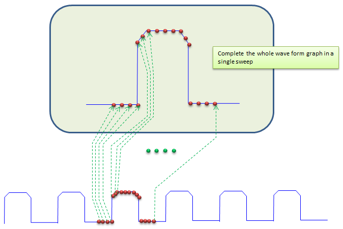
Before we look into 'Sampling Oscilloscope', let's think of how the normal Sample-and-Storage oscilloscope works. It works as illustrated below. If you hit the measure button or it got triggered by a preset trigger, it start sample at a certain speed. The sampling speed should be much higher than the frequency of the signal you want to measure. And it just plots all the sampled point on the screen and draw connecting lines between each sample points. so the whole graph on the screen is drawn by single sweep.
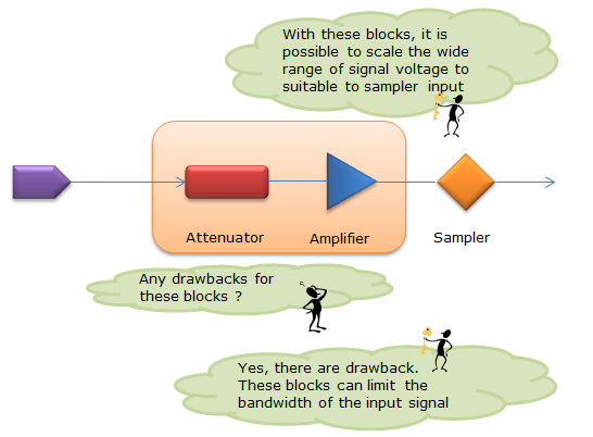
A very much simplified block diagram for sample-and-storage oscilloscope can be illustrated as below. One thing you should notice is that the signal gets attenuated or amplified according to the display range set by the user before it gets sampled. It means this type of oscilloscope can measure very wide range of the input signal. However, there is some drawback caused by this kind of scaling block (Attenuator/Amplifier). Almost any electrical component gives the expected performance within a certain range of frequency. Practically, there is no electrical/RF component that gives the expected performance for all frequency range (from DC to inifinite frequency). So putting this kind of scaling blocks before the sampler means putting some frequency band restriction for the input signal.
Sampling Scope
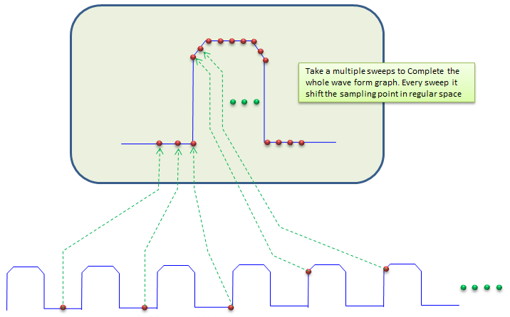
Unlink the sample-and-storage oscilloscope I described above, in sampling oscilloscope sampling is done usually much slower rate than the signal frequency. Then how we can measure the whole signal accurately with much slower sampling rate. There is some trick for this. In stead of sampling at low rate, it samples the differents points over multiple cycles of the signal and combine all those sampled points onto a display as if they are obtained by single sweep. It is a little hard to explain in words and can be confusing, but if you see the illustration below it would be easier to understand. However, to apply this technology there are a certain precodition (requirement) for the signal to be measured. i) it should be cyclical (repetitive) ii) the distance (time gap) between the sampling points should be different, otherwise it may sample the same points of the cyclic signal over and over and eventually you would see only one point on the screen in worst case. Assuming that the input signal is cyclic, now the important issue is how to make the sampling point differently so that they are not overlapping. How can we do this ? Usually two different techniques are used. One of the technique is illustrated as below. In this method, everytime it samples it increments the distance (timing distance) from previous sampling point by small steps.
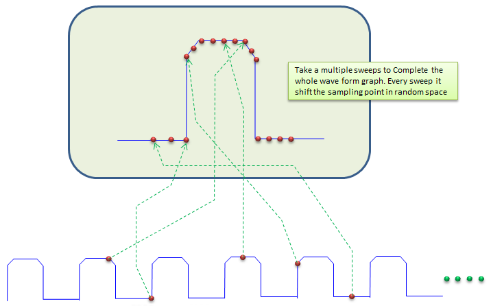
The other method is to use random sampling. As the term implies, it just samples in random time interval as illustrated below.
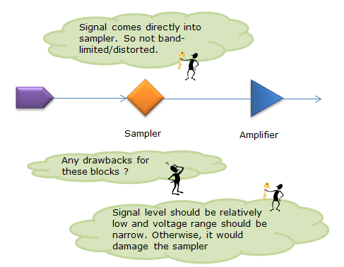
Sampling Oscilloscope is normally used to measure very high frequency signal and sometimes very wide band signal as well. Especially for wideband signaling, we cannot use 'Scaling block (Attenuator/Ampifier)' before the sampler since those scaler would limit the frequency range. It means the input signal goes directly into the sampler as shown below. So the input signal level for Sampling Scope should be very narraw range of voltage (usually within a few volts). Also it usually requires very accurate calibration process before the measurement especially when you try to measure very high frequency signal. Also impendence matching between equipment input port and the connected signal port is important. Simply put, you have to take most of precautious steps you take when you are tesing RF component with network analyzer.
|
||