Antenna Port
I think one of the most confusing concept in LTE physical layer is the concept of 'Antenna port'. The official definition of Antenna port goes as follows. (To be honest, this official definition does not make any clear sense to me)
36.211 5.2.1 Resource grid (Uplink) says :
An antenna port is defined such that the channel over which a symbol on the antenna port is conveyed can be inferred from the channel over which another symbol on the same antenna port is conveyed. There is one resource grid per antenna port. The antenna ports used for transmission of a physical channel or signal depends on the number of antenna ports configured for the physical channel or signal as shown in Table 5.2.1-1.
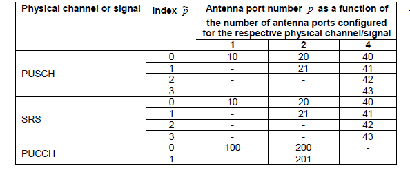
< 36.211 - Table 5.2.1-1: Antenna ports used for different physical channels and signals >
36.211 6.2.1 Resource grid (Downlink) says :
An antenna port is defined such that the channel over which a symbol on the antenna port is conveyed can be inferred from the channel over which another symbol on the same antenna port is conveyed. For MBSFN reference signals, positioning reference signals, UE-specific reference signals associated with PDSCH and demodulation reference signals associated with EPDCCH, there are limits given below within which the channel can be inferred from one symbol to another symbol on the same antenna port. There is one resource grid per antenna port. The set of antenna ports supported depends on the reference signal configuration in the cell:
|
Reference Signal Type |
Associated Antenna Ports |
|
Cell-Specific Reference Signal |
p = 0, p ∈ {0,1}, p ∈ {0,1,2,3} |
|
MBSFN |
p = 4 |
|
UE-Specific Reference Signal |
p = 5, p = 6, p = 7, p = 8 , one/several of p ∈ {7,8,9,10,11,12,13,14} |
|
DMRS for EPDCCH |
p ∈ {107,108,109,110} |
|
Positioning Reference Signal |
p = 6 |
|
CSI Reference signal |
P = 15, p = 15,16, p = 15,16,17,18, p = 15,16,17,18,19,20,21,22, p = 15,16,17,18,19,20,21,22,23,24,25,26, p = 15,16,17,18,19,20,21,22,23,24,25,26,27,28,29,30 |
NOTE : As you see here, there are several different port combinations for a specific refernece signal type. Which of the combination is used is determined by a specific antenna configuration (i.e, Transmission Mode). For further details on the antenna port combination and each transmission mode and reference signal, refer to Transmission Mode page and Reference Signal (Downlink) page.
Simply put,
- Antenna port is logical concept, not a physical concept (meaning 'Antenna port' is not the same as 'Physical Antenna')
- Each Antenna port represents a specific channel model
- The channel that is transmitted by a specific antenna port can be done by using the reference signal assinged fort the port (This is why each antenna port has its own reference signal)
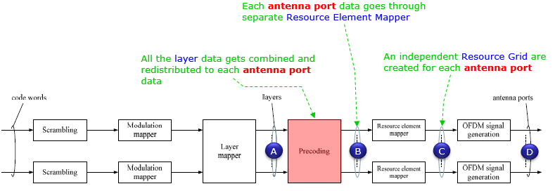
To be honest, any of the verbal description of Antenna port was not so clear to me for a long time. I am kind of person who has huge difficulties on understanding things if I don't visualize it (have any form of visual image). Just to give you another angle of the concept of Antenna port, I will try to show you on exactly which point in physical layer processing the antenna port are introduced. As illustrated below, antenna port is introduced in Precoding process at first and each antenna port will generate its own resource grid.
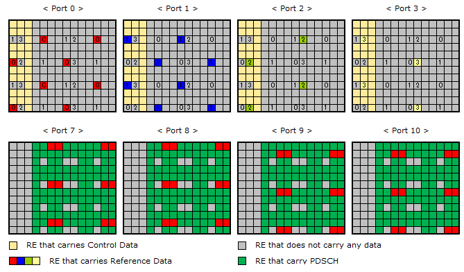
Now let's take a look at some of practical examples of how each of antenna port are associted each resource grid. These example shows the all the resource grid that can be observed at point (C) on the physical layer processing shown above. In these examples, I will draw the resource grid with only one RB just for simplicity.
Example 1 > 4x4 MIMO, Transmission Mode 3 or 4.
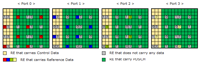
Example 2 > Transmission Mode 9, 4 Layer.