Simply put, SAE is just a terminology representing LTE network architecture. More simply put, SAE = LTE Network -:). If I represent it graphically, it looks as follows. You will find the various different type of SAE diagram from various source ranging from very simple to extremly complicated one. Following is a kind of simple presentation but it has almost everything of LTE component. The complicated diagram you would find from other source is just a combination of LTE network and other networks like UMTS, GSM etc.
In the 3GPP specifications, SAE stands for System Architecture Evolution, the work item that defined the LTE core network. The result of that work is the EPS, which is the E-UTRAN radio network plus the EPC core network. 23.401 defines the EPC nodes and the reference points between them, and this page follows that split.
Followings are the topics to be covered in this page.
SAE Network Diagram
Which boxes make up an LTE network, and how are they connected? The diagram below answers that with the smallest set of nodes that still covers attach, data transfer, policy and mobility to 3G. Each line in it is a reference point with its own name and protocol in 23.401.
The UE sits on the left, and the dashed line separates the eNodeB from the core network. The MME, HSS and SGSN form the control part at the top, and the SGW and PGW carry the user data to the IP network on the right. The PCRF sits above the PGW.

The LTE SAE with the nodes of the EPC. The eNodeB connects to the MME for control and to the SGW for user data.
The table below names each line of the diagram. The names come from the non-roaming architecture of 23.401 v20.0.0 clause 4.2. The line between the SGSN and the PGW is the Gn/Gp interface of a pre-Release 8 SGSN, where the PGW acts as a GGSN. A Release 8 S4-SGSN connects to the SGW over S4 instead.
Line in the diagram | Reference point | What it carries |
eNodeB - MME | S1-MME | control plane between E-UTRAN and MME |
eNodeB - SGW | S1-U | user plane tunnel per bearer |
MME - SGW | S11 | control plane between MME and SGW |
MME - HSS | S6a | subscription and authentication data |
MME - SGSN | S3 | UE and bearer context for mobility to 2G and 3G |
SGW - PGW | S5, or S8 when roaming | user plane tunnel and tunnel management |
PGW - PCRF | Gx | QoS policy and charging rules |
PGW - IP | SGi | connection to the packet data network |
SGSN - PGW | Gn/Gp | pre-Release 8 SGSN to the PGW acting as GGSN |
Video Tutorials :
Control plane : eNodeB, MME, HSS and SGSN, over S1-MME, S6a and S3.User plane : eNodeB, SGW, PGW and the IP network, over S1-U, S5/S8 and SGi.Policy : PCRF to PGW over Gx.
Interworking with 2G and 3G
LTE started as a packet-only network, so an operator needs a path back to the 2G and 3G circuit-switched core for voice. The diagram below adds GSM and UMTS to the SAE and shows the one link that makes CSFB possible.
You can extend the LET SAE as follows to interface with other technology.
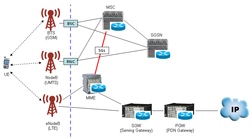
SAE with GSM and UMTS. The red line is the SGs interface between the MME and the MSC.
The UE can reach three radio networks: GSM through the BTS and BSC, UMTS through the NodeB and RNC, and LTE through the eNodeB. The BSC and RNC connect to the MSC for circuit-switched calls and to the SGSN for packet data. On the LTE side, the eNodeB connects to the MME and the SGW, as in the diagram above.
The red SGs line is the only link between the LTE core and the circuit-switched core. 23.272 v20.0.0 defines SGs as the reference point between the MME and the MSC server, based on the Gs interface of 2G/3G. The MSC uses it to page a UE in LTE for an incoming call, and the MME uses it to register the UE in the CS domain. SMS over SGs also uses this link, so a UE can send and receive SMS without leaving LTE.
SGs links the MME and the MSC : 23.272 clause 4.CS paging and registration : the basis of CSFB.SMS over SGs : SMS without a fallback to 2G or 3G.
Function of each Node
Now you'd better understand function of each node (block) in the diagram. The more you know about each of these blocks, the easier your troubleshooting, test case creation, test will be since the role of each of these nodes will be related to the information elements (IE) of RRC/NAS message. But here I would just put the brief summary of functions of each node and I leave it to you to dig into the details.
MME - Mobility Management Entity
Just remember this as the most important component of SAE which has following functionality. You can take MME as a center for all signaling message.
- Idle mode UE (User Equipment) tracking Process
- Paging Process.
- Bearer activation/deactivation process
- Choosing the SGW for a UE at the initial attach
- Core Network (CN) node relocation at time of intra-LTE handover
- Authenticating the user (by interacting with the HSS)
- Destination of NAS message
- Generation and allocation of temporary identities to UEs.
- Authorization of the UE to camp on the service provider’s Public Land Mobile Network (PLMN)
- Enforces UE roaming restrictions
- Termination Point for Ciphering/Integrity for NAS signaling
- Security key management
- Lawful interception of signaling is also supported by the MME
- Provides the control plane function for mobility between LTE and 2G/3G access networks in connection to SGSN
SGW - Serving Gateway
Simply put, this is a center for all user data (packet data). For each UE, a single SGW handles the user plane at any time, and it terminates the S1-U interface from the eNodeB.
- Routes and forwards user data packets
- Act as the mobility anchor for the user plane during inter-eNodeB handovers
- Act as the anchor for mobility between LTE and other 3GPP technologies
- Terminates the DL data path and triggers paging when DL data arrives for the UE when UE is in Idle mode
- Manages and stores UE contexts, e.g. parameters of the IP bearer service, network internal routing information
- Performs replication of the user traffic in case of lawful interception
PGW - PDN Gateway
The PGW is the gateway that terminates the SGi interface towards the packet data network. It allocates the UE IP address and applies the policy that the PCRF sends over Gx. A UE that uses several PDNs can have more than one PGW.
- Provides connectivity from the UE to external packet data networks
- Performs policy enforcement, packet filtering for each user, charging support, lawful Interception and packet screening
- Act as the anchor for mobility between 3GPP and non-3GPP technologies such as WiMAX and 3GPP2 (CDMA 1X and EvDO)
HSS - Home Subscriber Server
This is a central database that contains user-related and subscription-related information. It is like "HLR(WCDMA) + AuC(WCDMA) + Additional Information(LTE)" The MME reads the subscription data and the authentication vectors from the HSS over S6a.
- Mobility management
- Call and session establishment support
- User authentification and access authorization
PCRF - Policy and Charging Rules Function
The PCRF is the policy and charging control element of 23.203, and it appears above the PGW in the SAE network diagram. It decides the QoS and charging rules for each service, and it sends them to the PGW over Gx. An application function such as the IMS P-CSCF reaches it over Rx.
Gx towards the PGW : QoS and charging rules.Rx towards the application function : service information, for example for IMS voice.One PCRF per UE session in non-roaming : H-PCRF and V-PCRF with local breakout.
eNodeB
The eNodeB is the only node of the E-UTRAN, and it has no controller above it as the NodeB has the RNC. 36.300 describes its radio functions. 23.401 clause 4.4.1 adds the functions it performs for the EPC, which are listed below.
MME selection : when the UE gives no information to route to an MME.Bearer rate enforcement : UE-AMBR and MBR in the uplink scheduler, UE-AMBR in the downlink.Admission control and packet marking : per bearer, with the DSCP set from the QCI.
Reference
[1] 3GPP TS 23.401 v20.0.0 - clause 4.2, Architecture reference model, and clause 4.4, Network elements
[2] 3GPP TS 23.272 v20.0.0 - Circuit Switched Fallback in EPS, SGs reference point
[3] 3GPP TS 36.300 - E-UTRA and E-UTRAN overall description