|
Mechanical Engineering |
||
|
Fluid Mechanics : Linear and Angular Momentum
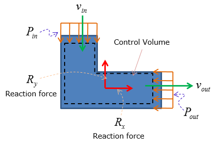
Linear and angular momentum equations are used to calculate the reaction forces and moments exerted by the control volume to maintain static equilibrium under applied forces and/or moments by the working fluid(s)
In engineering and real-life, examples of linear and angular momentum equation application include:
Linear momentum equation
The linear momentum equation is used to calculate the reaction forces on a control volume to maintain static equilibrium
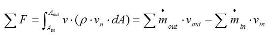
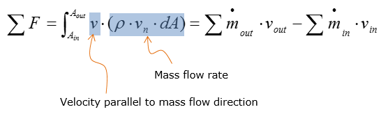
The equation is initially stated (in general)as following for steady-state condition:
Meaning of some important terms in this equation is as follows :
The equation above states that sum of the forces are equal to the difference between mass flow rate times velocity parallel to the force at the outlet and inlet of the control volume Static pressure of the working fluid at the inlet and outlet are also elements of forces on the control volume, affecting the magnitude of reaction forces: static pressure always acts into the control volume
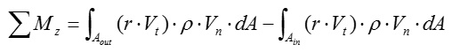
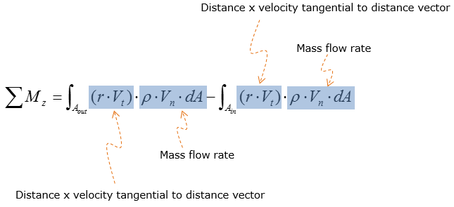
Angular momentum equation
The angular momentum equation is used to calculate the reaction moment on the control volume. Unlike the linear momentum equation, the static pressure at the inlet and outlet of the control volume does not affect the magnitude of the reaction moment. To calculate reaction moment, one must compute the distance between the inlet/outlet of the control volume and the location of the support system. For fluid-powered systems, screws are the most typical hardware used as support system that induce reaction forces and moments.
Meaning of some important terms in this equation is as follows :
Example 1 >
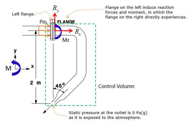
Water flows through the pipe shown at a rate of 250 litres/minute. It discharges to atmosphere at the nozzle outlet. The pipe has an inside diameter of 30 mm and the nozzle an inside diameter of 15 mm. The water pressure at the flange is 300 kPa(g). Determine the forces and moments the left flange exerts on the right flange. The pipe lies in the horizontal plane. Neglect the weight of the pipe itself and the water inside it.
Step 1: List the assumptions
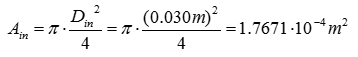
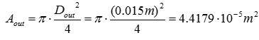
Step 2: Analyze the inlet and outlet properties As the cross-sectional area of the inlet and outlet are required to calculate the reaction forces, start off by calculating the cross-sectional area at the inlet and outlet of the control volume:
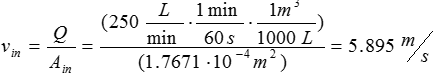
Apply the given volumetric flow rate and the calculated cross-sectional areas to calculate the velocity of water at the inlet and outlet:
Rearrange the volumetric flow rate equation above for v
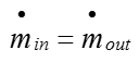
Use the velocity expression above to calculate the inlet and outlet velocities of water. Convert the given volumetric flow rate to m^3/s to compute for velocities in m/s. Recall that volumetric flow rate is equal at the inlet and outlet as the flow is assumed to be steady-state and water is incompressible.
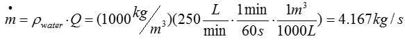
Calculate the mass flow rate through the system. Recall that the mass flow rate at the inlet and outlet of the control volume are equal based on steady-state assumption.
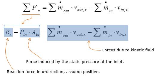
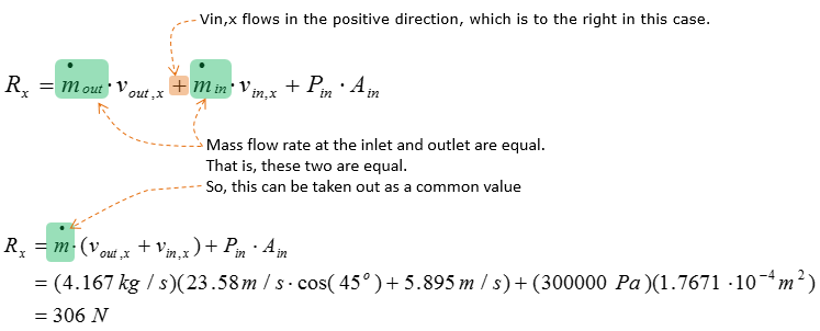
Step 3: Calculate the reaction forces Now that the velocity and cross-sectional area at the inlet and outlet are computed, linear momentum equation is now ready to be used to calculate the reaction forces induced by the flange, both in the x and y direction.
Consider the reaction force analysis in the x-direction. Let Rx be the reaction force in the x-direction
Expand and simplify the expression of forces due to kinetic fluid. This step is used to prepare the equation for plug and chug analysis.
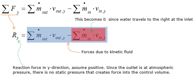
Consider the reaction force analysis in the y-direction. Let Ry be the reaction force in the y-direction.
Reaction force in y-direction, assume positive. Since the outlet is at atmospheric pressure, there is no static pressure that creates force into the control volume.
Expand on the linear momentum equation for Ry and then calculate Ry.
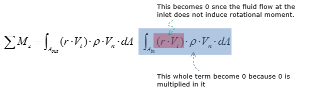
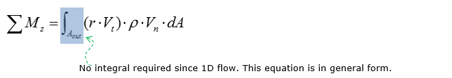
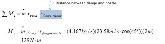
Step 4: calculate the reaction moment Since the flange is right beside the inlet, the forces on the inlet does not induce a rotational moment on the control volume. However, the outlet of the control volume is located 2m below the inlet, inducing a rotational moment since there is water flowing out of the nozzle (outlet in this case). The nozzle is oriented 45 degrees below horizontal, which indicates that only the horizontal component of the water velocity induces the force that creates the rotational moment about the flange. Then the reaction moment generated by the flange is calculated by multiplying the force and the vertical distance from the flange.
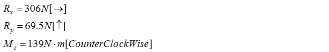
Now let's summarize all the result we got. The magnitude of reaction forces and moment are stated below.
|
||