|
Mechanical Engineering |
||
|
Linkage System : Relative Motion Analysis : Velocity
All of linkage system problems involve relative-motion analysis because the motion of a link is affected directly by the motion of its adjacent link Must be comfortable with setting up vectors as well as executing vector addition, subtraction, and multiplication by hand Scalar method/approach can also be used as an alternative method for the vector method and is favored over the vector method as it is less time consuming
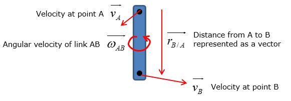
Let's consider a simple linkage system as shown below
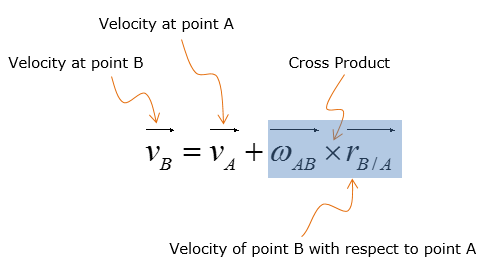
Velocity of the link at point B is calculated by using the following equation if vector method is to be used
Putting a short description on this equation as follows would help you with understanding this equation. The equation states that the velocity at point B of the rotating link AB is dependent on the sum of the velocity at point A and velocity of point B with respect to point A
Example 1 >
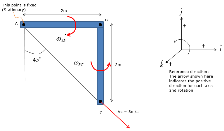
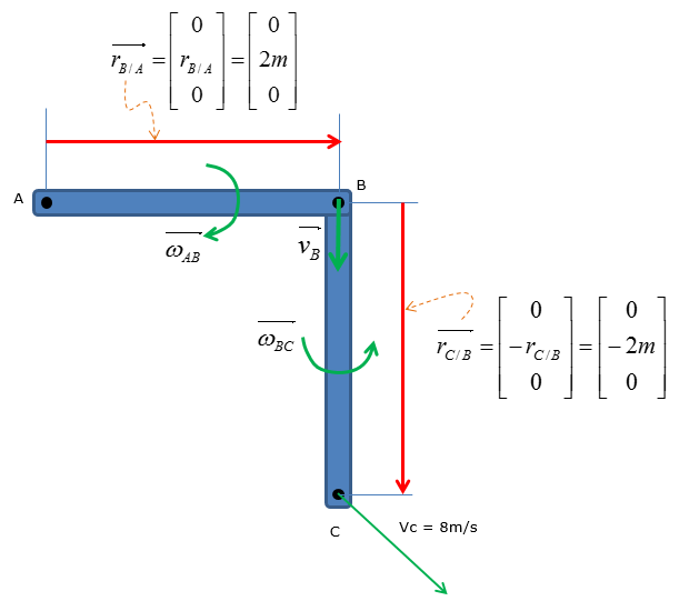
The slider block C moves at 8 m/s down the inclined groove. Determine the angular velocities of links AB and BC, at the instant shown.
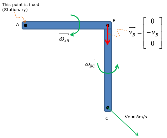
Step 1 > Situational analysis – set up the vectors
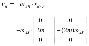
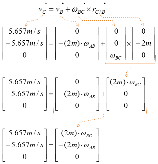
Step 2 > Plug in the vectors into the relative velocity equations to obtain simplified expressions
Example 2 > Scalar method of relative velocity analysis
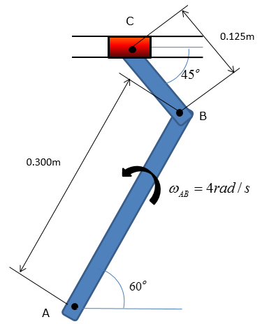
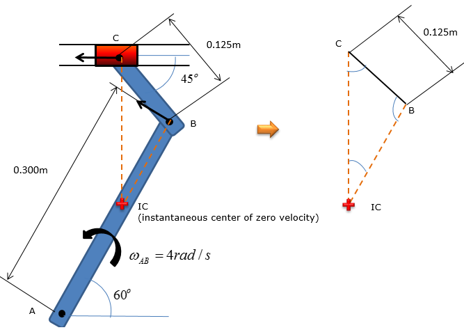
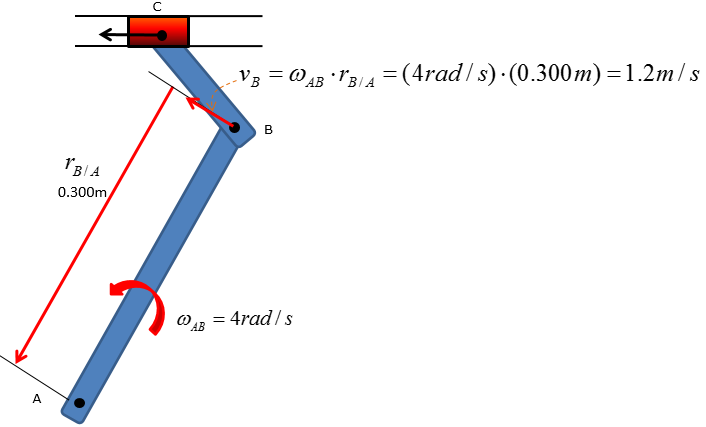
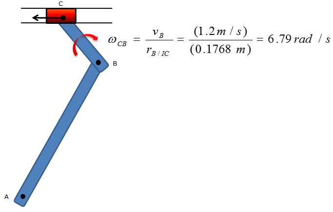
Scalar method of relative velocity analysisThe shaper mechanism is designed to give a slow cutting stroke and a quick return to a blade attached to the slider at C. Determine the angular velocity of the link CB at the instant shown, if the link AB is rotating at 4 rad/s
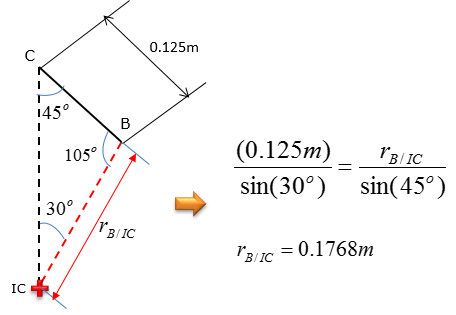
Step 1 > locate the instantaneous center of zero velocity
Step 2 > Calculate the angular velocity of link CB
|
||
