|
Mechanical Engineering |
||
|
Mechanics : 3D Rigid Body
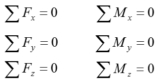
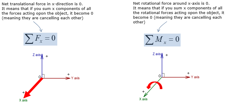
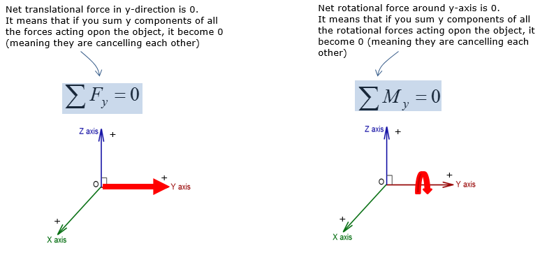
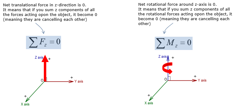
3D rigid body equilibrium analysis involves calculating forces in the x,y, and z direction, as well as calculating moments about the x,y, and z axis. The types of reaction supports from 2D rigid body equilibrium are not applicable to 3D rigid body equilibrium. However, the rigid body equilibrium concepts in 2D and 3D are no different, where the net force and moment in all directions must be equal to zero to maintain static equilibrium. Since 3D rigid body equilibrium analysis is time consuming due to forces and moments in 3 dimensions, 2D rigid body equilibrium analysis is always preferred. However there are many engineering problems that require 3D rigid body equilibrium analysis. Examples of 3D rigid body equilibrium analysis in engineering include: reaction force and moment analysis of airplane wing during takeoff, calculating reactions on construction equipments during operation
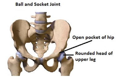
Ball-and-socket joints are one of the most practical supports in mechanical systems engineering. Interestingly enough, our legs are joined by a ball-and-socket joint to our hipbones.
Tips on 3D rigid body equilibrium
There are a number of different supports for 3D rigid body equilibrium, as you saw. It is hard to memorize all the support reactions. But on the midterm or exam, you never know what type of 3D supports you will have to work with while you are most likely required to have them memorized. In order to be comfortable with any 3D supports without having to look back to the textbook (or your notes), practice solving the problems for all types of 3D supports in the first year Mechanics textbook
The most typical 3D supports that you run into during the midterm or exam are: ball and socket joints, fixed support, and roller (or equivalent)
Always start the problems by drawing the Free-Body-Diagram and computing the directional vectors for the applied forces
Additionally, all the problem solving questions on the midterm and exam tends to be copy and pasted from the textbook, as it is easier for the professors
Example 01 >
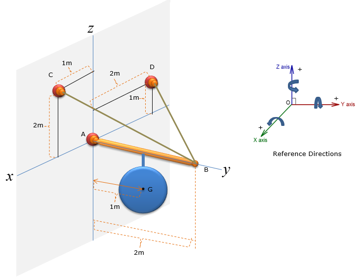
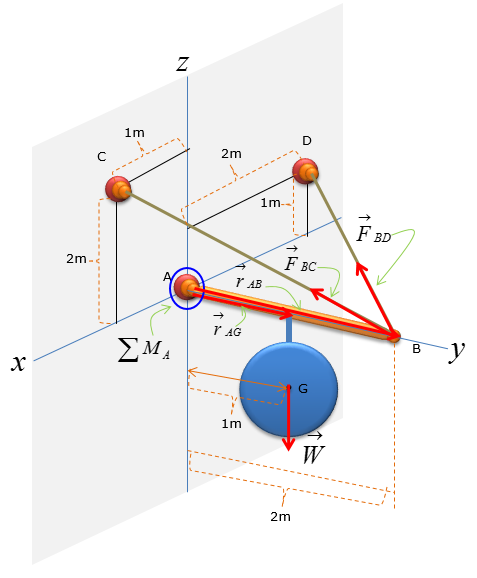
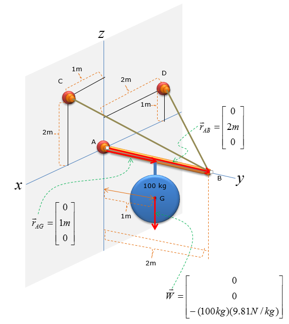
A pole has a mass of 100kg with the centre of mass at G. Determine the x, y and z components of the reaction at the ball-and-socket joint at A, and determine the tension in wires BC and BD. (NOTE : I put a mass with the shape of a circle just to simplify the drawing, but in real application this can be any other object like a sign)
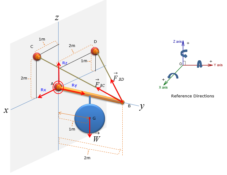
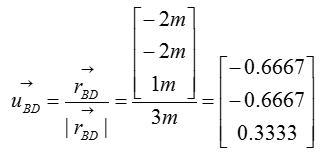
Step 1 : Draw Free Body Diagram
Step 2 : Compute the directional vectors for Force along BC and BD
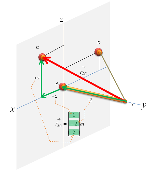
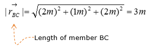
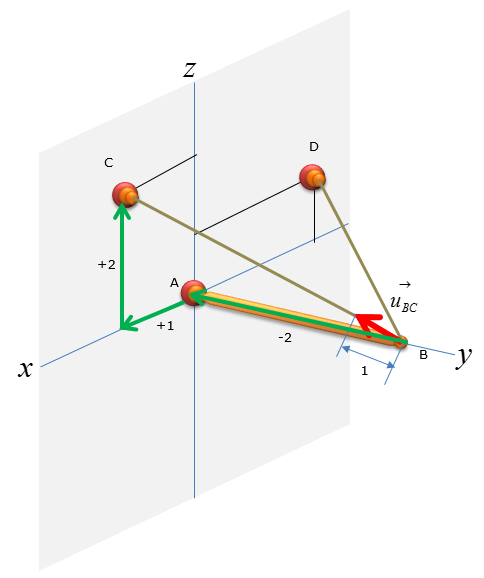
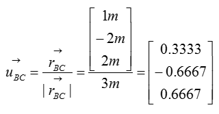
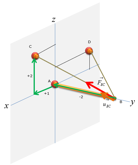
First, let's think of the wire connecting the point B and C
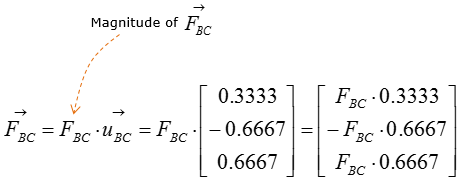
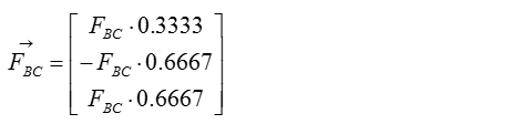
Now let's figure out the unit vector pointing from B to C. We need to compute the unit vectors to analyze the magnitude of the tensional forces in x,y,z direction. The magnitude of tensional forces in each direction are used to calculate the reaction forces at point A, which is the ball-and-socket joint. Before calculating for the tensional forces along the line of action BC and BD, the forces must be expressed as vectors for moment analysis at point A without having to do separate moment analysis about x,y,and z directions. Knowing how to do vector cross-product allows you to do the moment analysis with just one equation, instead of having to use 3 separate moment equations about the x,y, and z directions.
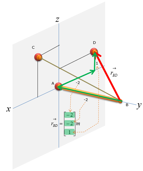
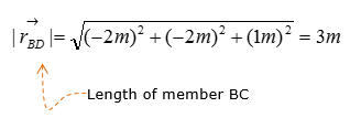
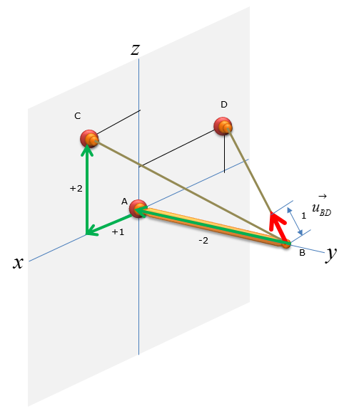
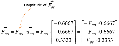
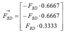
Next, let's think of the wire connecting the point B and D
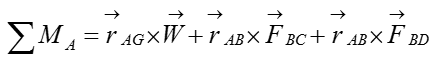
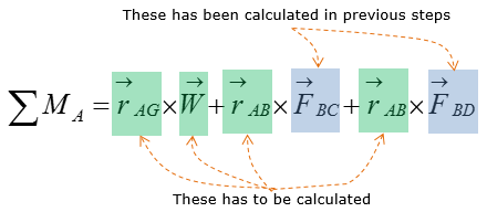
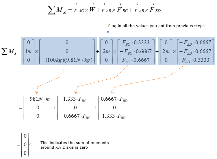
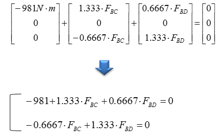
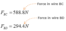
Step 3 : Take the moment about A to calculate the magnitude of F1 and F2. Set counter-clockwise moment to be positive. Point A is the only point suitable for taking the moment about as the system can only pivot about that point
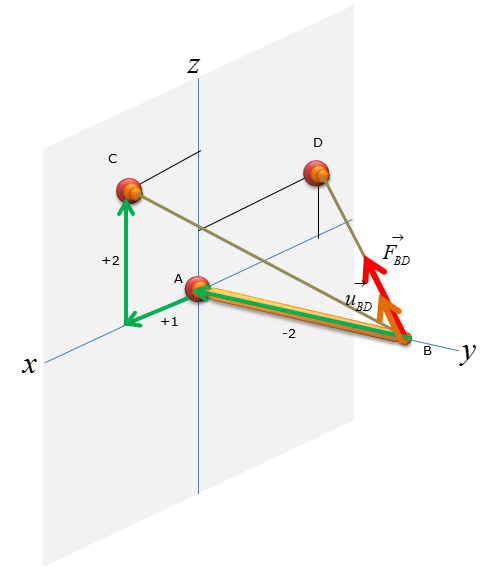
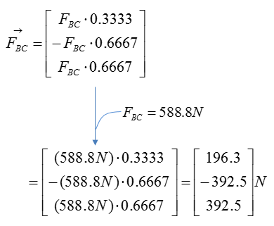
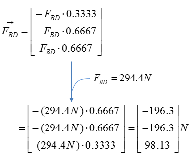
Step 3 : Compute the force vectors F_BC and F_BD, since their magnitude is now known. The force vectors will be used to calculate the reaction forces at point A.
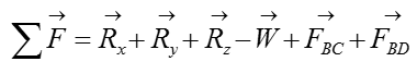
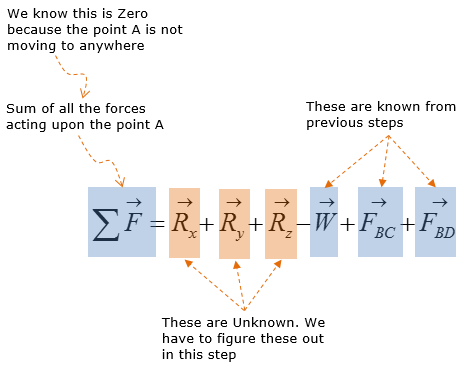
Step 4 : Analyze the forces: Consider the reaction forces
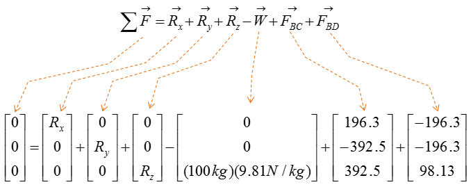
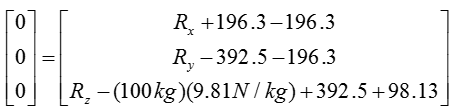
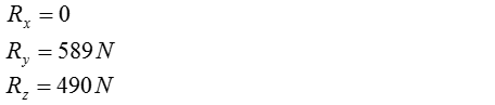
Calculate the reaction forces at point A using sum of force analysis in x,y,z direction. For 3D rigid body equilibrium analysis, the most effective method of sum of force analysis is to add all the vectors in the free-body-diagram (FBD) and then solve for the reaction forces.
|
||