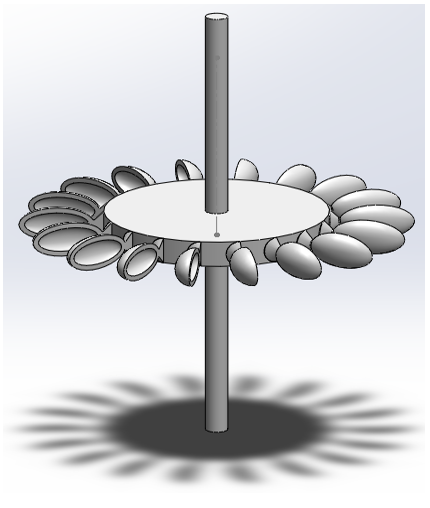
Mini Project : PeltonTurbine : Blade (I)
Following is the final result that we want to design in this tutorial.
Step 1 > Create the center Cylinder
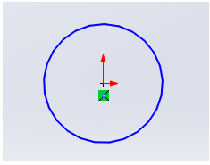
Draw a circle with the radius that you want.
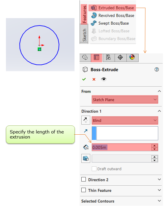
Select the circle and open up [Extruded Boss/Base] menu and specify {From} and {Direction 1} parameter as follows.
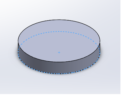
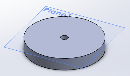
Then you will get a thin cylinderical object as shown below.
Step 2 > Make a Shaft Hole
At this step, we will make a through hole at the center of the cylinder and the overall procedures is as follows.
i) draw a small circle right on a plane defined right at the surface of the cylinder
ii) Extrude-cut the circuit through the cylinder
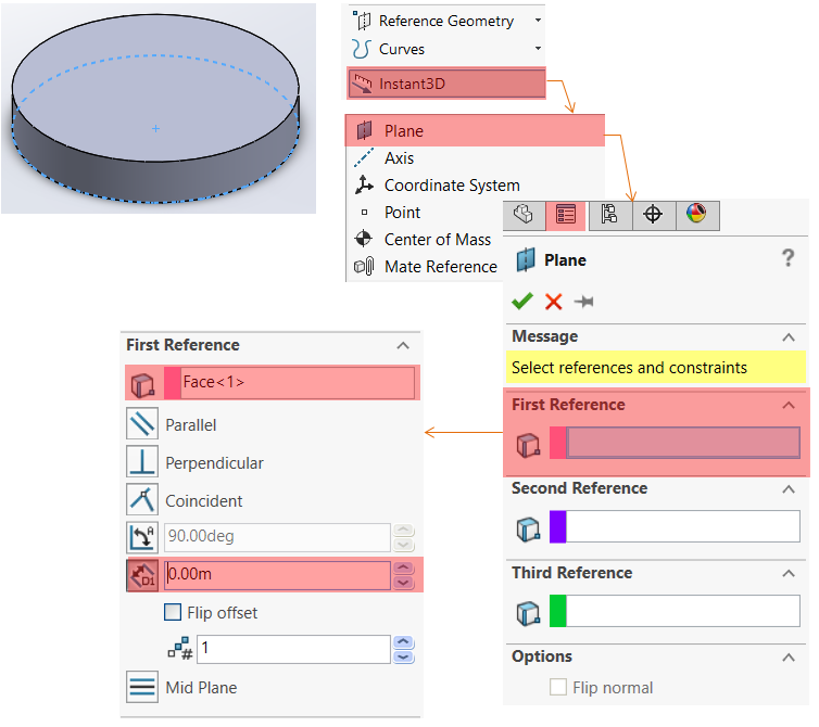
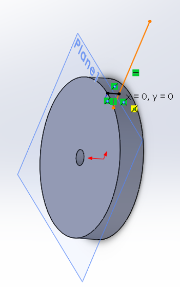
Select the cylinder and run [Instant3D] menu and run [Plane] menu. Specify the {First Reference} parameters as shown below. The important point is to specify 0.00 m to locate the plane right on top of cylinder surface.
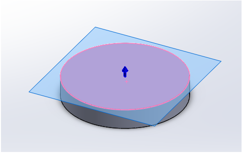
Now you see a new plane is created at the surface of the cylinder as shown below.
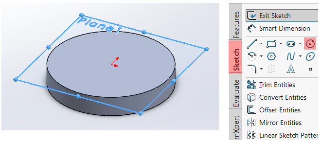
Draw a small circle on the plane. The center of the circle should be set at the center of the cylinder.
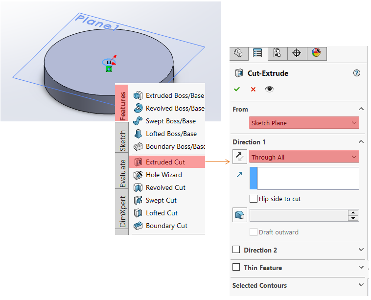
Select the circle you just drew and run [Extrude-Cut] menu as shown below.
Now you get a through-hole at the center of the cylinder as shown below.
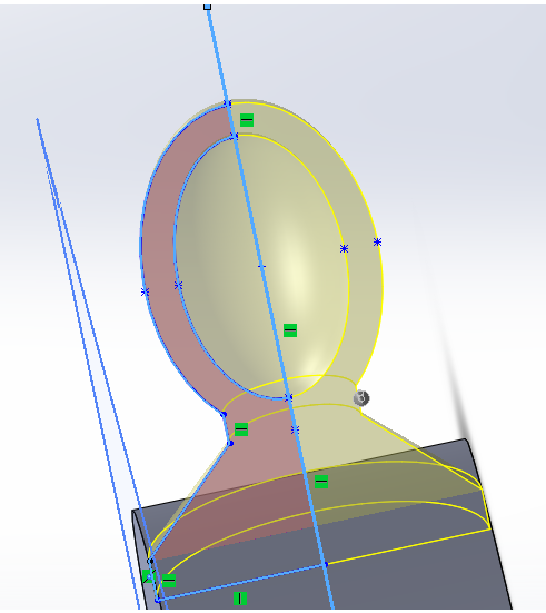
Step 3 > Draw a scoup on the surface of central cylinder
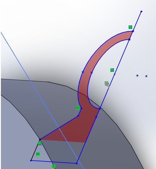
Draw a line that will be used as an axis of rotation (the orrange line as shown in below.)
Draw a shape as shown below (the shape drawn in blue line). I assume that you are familiar enough to Solidworks to draw this kind of shape without any additional explanation.
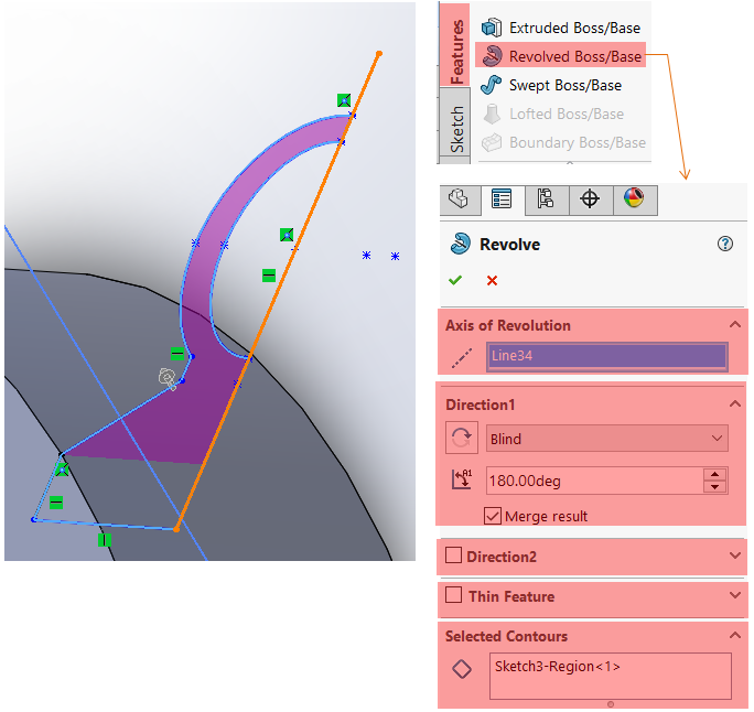
Run [Revolved Boss/Base] menu and set the parameters as shown below. NOTE : In this tutorial, the item in "Axis of Revolution" is set to be 'Line34'. The 'Line34' is the orange line shown below (You may see different name in your drawing.)
Running the function set above, you will get the 3D object as shown below.
Step 4 > Multiplicates the scoupe around the circumference of central cylinder
At this step, we will multiplicate the object (scoupe) along the circumference of the centeral cylinder. We will use [Pattern] function for this. With using this function, we can easily multiplicate an object without redrawing it from scratch.
Arrange the object as shown below to make it easier to draw a center line for Circular Pattern generation.
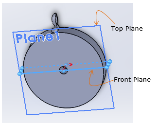
Select [Front Plane] (We will draw a line right in the middle of this plane)
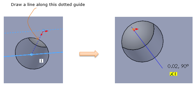
Zoom into the center hole on the central cylinder so that you can easily see the guide line at the center and draw a line as shown below.
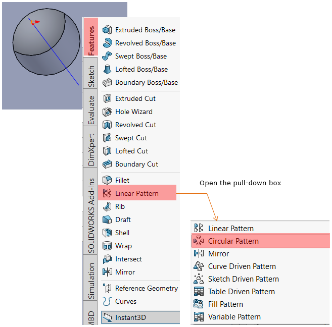
Open up the Pattern menu dropdown box and select [Circular Pattern].
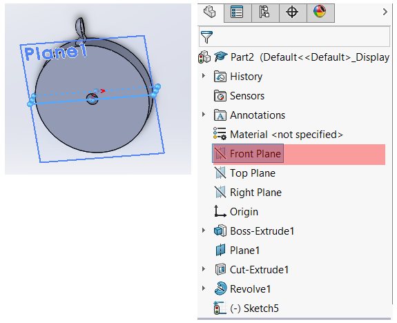
Now specify [Circular Pattern] parameter as shown below.
"Sketch5" indicate the center line you drew above (You may see different name in your drawing)
"Revolve1" indicate the object that will be multiplicated.
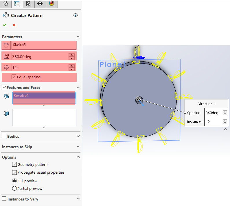
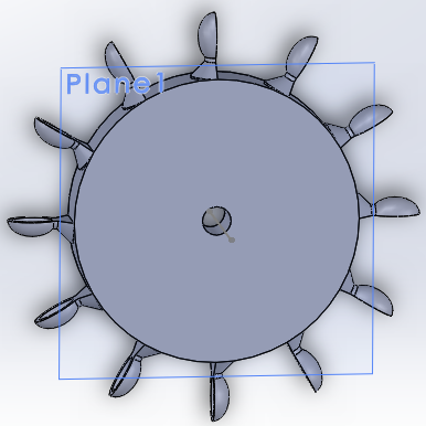
Applying the settings as above, you will get the object as shown below.
Reference :
[1]