|
SolidWorks |
||
|
Basics : New File : Parts Design
Since Solidworks has become such a common (dominant) tool in mechanical design, it would be hard to find such a tutorial starting from the ultimate basic like this. However, for those who never touched the tool before every single step even at the very basic level would be a big hurdle to overcome. This tutorial is for one of such a basic thing.. It is about opening a new design file and take the first look of the layout.
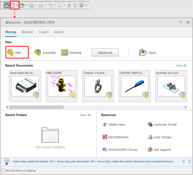
Launching SolidWorks and click on [New] button, you will have a selection screen as shown below. You need to chose one among Part, Assembly, Drawing. If you want to draw a new object (this is the most common operation), you should select [Part] , not [Drawing].
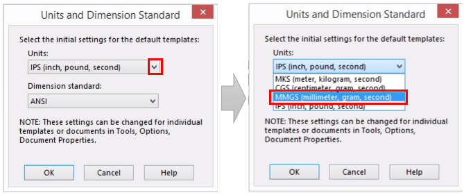
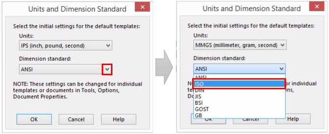
Then you will get another popup for specify the units and dimensional standards. I don't think you need any explanation on this screen but I would suggest you to keep in mind on what you selected here so that you can have a good image of the real scale of the object when you are drawing it. Since you can scale up and down the object on the screen to any degree, it is hard to imagin a real/physical size of the object at the time of drawing. Otherwise, when you may be surprised to see the real size of the object when it comes out of 3D printer or CNC machine :)
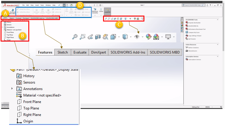
Selecting all those options, you will have the design screen as shown below. It is impossible and inefficient to explain on the details of every part of the tools on the screen for now. Just take a look around a few important sections as shown below. These are the tools and options that you will use in most of the design process.
Reference :
[1]
|
||