A TD-SCDMA handover moves a connected UE to a new cell with a Physical Channel Reconfiguration. The difficult part is the uplink timing. TD-SCDMA is a TDD system, so the UE must transmit inside the uplink slot of the target cell at the right moment. But the UE does not yet know how far it is from the new Node B. This page shows the message sequence first and then the two ways to solve the timing problem. At the end, it shows how a handover looks in a trace and on a spectrum analyzer.
- Overall Sequence
- Baton vs Hard Handover
- N Frequency Handover
- Power Profiles during Handover - Example
- Reference
Overall Sequence
Overall sequence for TDSCDMA Handover is as illustrated below. (The illustration below is for Hard handover which requires Synchorinization process during the handover). The source cell is BTS1 and the target cell is BTS2. The handover command comes from BTS1, and everything after the switch goes to BTS2.
Why does the UE need an extra exchange with BTS2? An uplink traffic burst has a guard period of only 16 chips, which is 12.5 microseconds at 1.28 Mcps. But the UE does not know its round trip delay to BTS2 yet. So the UE first sends a SYNC-UL code in UpPTS, a special slot outside the traffic slots. A code with the wrong timing there does not disturb other UEs in the traffic slots. The diagram below shows this exchange between the reconfiguration and the Complete message.
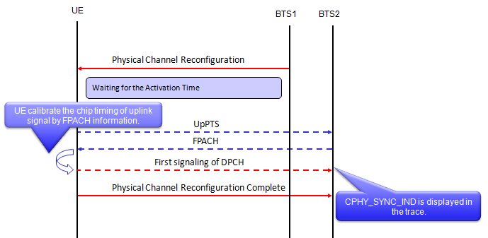
Hard handover sequence in TD-SCDMA. The UE sends UpPTS to the target cell and waits for the FPACH before it sends the first DPCH burst.
BTS1 orders the handover with Physical Channel Reconfiguration : the message gives the target cell, its channels and the activation time.The UE waits for the activation time : nothing changes on the air until then.The UE sends UpPTS to BTS2 : this SYNC-UL transmission uses an open loop timing estimate from the downlink of BTS2.BTS2 answers on the FPACH : the answer carries the measured timing deviation, and the UE uses it to calibrate the chip timing of its uplink.The first DPCH burst goes to BTS2 with corrected timing : the trace shows CPHY_SYNC_IND at this point.Physical Channel Reconfiguration Complete goes to BTS2 : this message closes the handover.
Baton vs Hard Handover
There are two different types of Handover in TDSCDMA, one is Hard Handover and the other is Baton handover. As you see in the following protocol log, in Hard Hard handover UE and network goes through physical layer synchronization process through a kind of PRACH process. (This seems to be similar concept of LTE Handover)
In RRC messages, the difference is whether or not using the following parameter.
DL-DCCH-Message.message.physicalChannelReconfiguration.later-than-r3.criticalExtensions
.r4.physicalChannelReconfiguration-r4.ul-ChannelRequirement.ul-DPCH-Info.modeSpecificInfo
.tdd.ul-TimingAdvance
Hard Handover performHandover with TimingAdvance enabled and Baton Handover perform Handover with TimingAdvance disabled. So Hard handover would be more stable than Baton Handover
Let's look at how 25.331 v19.0.1 defines this IE. In 1.28 Mcps TDD, ul-TimingAdvance in the r4 message has the type UL-TimingAdvanceControl-LCR-r4. It is a choice between disabled and enabled, and enabled can carry the parameters of the SYNC-UL procedure.
Following is based on
UL-TimingAdvanceControl-LCR-r4 ::=	CHOICE {
	disabled							NULL,
	enabled								SEQUENCE {
		ul-SynchronisationParameters		UL-SynchronisationParameters-r4	OPTIONAL,
		synchronisationParameters			SynchronisationParameters-r4	OPTIONAL
	}
}

UL-SynchronisationParameters-r4 ::=	SEQUENCE {
	stepSize							INTEGER (1..8),
	frequency							INTEGER (1..8)
}

SynchronisationParameters-r4 ::=	SEQUENCE {
	sync-UL-CodesBitmap				BIT STRING {
											code7(0),
											code6(1),
											code5(2),
											code4(3),
											code3(4),
											code2(5),
											code1(6),
											code0(7)
											} (SIZE (8)),
	fpach-Info							FPACH-Info-r4,
	-- Actual value prxUpPCHdes = IE value - 120
	prxUpPCHdes						INTEGER (0..62),
	sync-UL-Procedure					SYNC-UL-Procedure-r4	OPTIONAL
}
Clause 8.6.6.26 of 25.331 gives three cases for 1.28 Mcps TDD. The first case is enabled with synchronisationParameters. The UE sends SYNC_UL codes on the UpPCH until the FPACH returns a timing correction. Then it starts on the assigned uplink resources. If no correction arrives within Max SYNC_UL transmissions, the UE treats it as a physical channel failure. This is the hard handover in the log below.
The second case is enabled without synchronisationParameters. In a cell change, the UE computes the new timing advance by itself as TAnew = TAold + 2Δt. Here Δt is the relative timing difference between the new and the old cell, as 25.224 defines it. The third case is disabled. The UE resets the timing advance to 0 and starts in the target cell without any timing advance.
The log below shows both types of handover from one test. Each one starts with MEASUREMENT CONTROL, MEASUREMENT REPORT and PHYSICAL CHANNEL RECONFIGURATION on the DCCH. In the hard handover, two lower layer lines follow: CPHY_UPPTS_TDS_IND on U PTS 0 and PHY_REPORT_TDS_IND on U PRACH 0. The baton handover has no such lines, and the Complete message follows the reconfiguration directly.
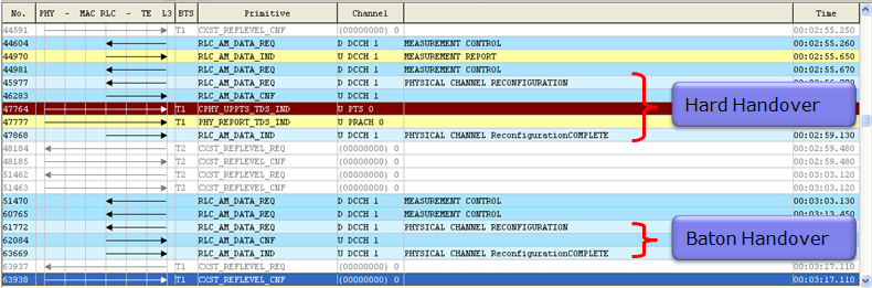
Hard handover and baton handover in one protocol log. Only the hard handover has an UpPTS transmission before the Complete message.
To synchronize UE and BTS in TD-SCDMA Hard Handover, the following procedure is used.
1. Send UpPCH signal from UE (Equivalent to Preamble in W-CDMA)
2. Send FPACH signal from BTS (Equivalent to AICH in W-CDMA)
3. Send PRACH signal from UE (Equivalent to PRACH in W-CDMA)
Unlike W-CDMA, TD-SCDMA works in TDD mode, it means the sending/receiving timing is very important.
The FPACH signal sent by BTS includes the information which indicates how far behind/ahead the UpPCH signal sent by ouUE is, compared to the BTS reference timing. i.e, FPACH carries the information on time difference between UpPCH and BTS Reference timing. Based on this information, UE determines the exact slot timing where PRACH should be transmitted.
This additional synchronization step may reduce the possibility of radio link failure during the handover and in turn reduce the chance of call drops. So Hard handover would be more commonly used than Baton Handover.
One detail is different in a handover. In random access, the burst after the FPACH is the PRACH. In a handover, 25.331 clause 8.6.6.26 lets the UE use its assigned uplink resources as soon as the timing correction arrives. So the third step is the first burst on the assigned uplink DPCH, as the sequence diagram in Overall Sequence shows. The tester log above still labels that burst as U PRACH 0.
The ul-TimingAdvance IE selects the handover type : enabled with synchronisationParameters gives the UpPCH and FPACH exchange of a hard handover.A hard handover measures the timing in the target cell : the FPACH returns the timing deviation, so the first DPCH burst arrives aligned.Without SYNC-UL, the UE starts with a computed or a zero timing advance : TAnew = TAold + 2Δt when enabled, and 0 when disabled.A failed SYNC-UL exchange is a physical channel failure : the UE does not transmit on the assigned DCH resources.
N Frequency Handover
A TD-SCDMA cell can have more than one carrier. 25.221 calls it a multi-frequency cell, and the carrier that transmits the P-CCPCH is the primary frequency. The other carriers are secondary frequencies, and a UE can hold its dedicated connection on one of them.
The sequence below starts on the primary frequency, Freq 1. Only Freq 1 has the sync signal and the common channels, so the UE reads the BCCH and sends RRC Connection Request there. RRC Connection Setup then moves the UE to the secondary frequency Freq 2, and the rest of the call setup runs on Freq 2. Later, a Physical Channel Reconfiguration hands the UE over to Freq 3 with a baton or hard handover.
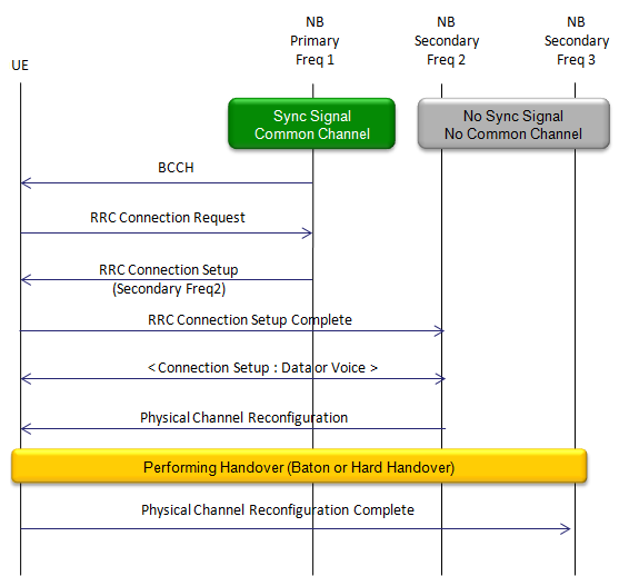
N frequency handover. The primary frequency carries the common channels, and the dedicated connection moves from secondary Freq 2 to secondary Freq 3.
The primary frequency carries the sync signal and the common channels : the UE camps there and starts the RRC connection there.RRC Connection Setup can move the UE to a secondary frequency : the Complete message is already sent on Freq 2.A handover can move the UE between secondary frequencies : the same baton or hard handover procedure applies.
Power Profiles during Handover - Example
Followings are acouple of screenshots showing the uplink power (UE TX power) during the handover. It would be hard to correlate this power data exactly to each steps of handover procedure.. but I hope this would give you some big picture.
Both screenshots come from a spectrum analyzer in power versus time mode. The small trace at the bottom covers the whole capture, and the blue box marks the part that the main trace shows. In the screenshot below, the main trace spans 20 ms from 1.2916 s. It shows four wide bursts, one every 5 ms sub-frame, and one narrow spike between them. The callouts on the bottom trace place the uplink sync signal inside this window and the first DPCH burst later.
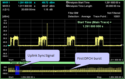
Uplink power in a 20 ms window around the uplink sync signal.
The next screenshot zooms into 152 ms from 1.551 s, where the callout marks the first U DPCH burst. The markers read -69.18 dBm at the start and -47.60 dBm at 1.703 s. So the UE raises its transmit power by about 21.6 dB in 152 ms, and the red line shows a steady ramp. This ramp follows the TPC commands of the new cell.

Uplink power ramp after the first DPCH burst in the target cell. The UE starts low and closed loop power control raises it step by step.
The uplink bursts repeat every 5 ms : a DPCH in one uplink slot sends one burst per sub-frame.The uplink sync signal comes before the first DPCH burst : the bottom trace shows the same order as the sequence diagram.The UE starts low and ramps up : TPC raises the power by about 21.6 dB in 152 ms.
Reference
- 3GPP TS 25.331 v19.0.1 : clause 8.6.6.26, UL Timing Advance Control, and the ASN.1 of UL-TimingAdvanceControl-LCR-r4
- 3GPP TS 25.224 v19.0.0 : clause 5.2, UL synchronisation for 1.28 Mcps TDD
- 3GPP TS 25.221 v19.0.0 : clause 5A.3.1, multi-frequency cell and primary frequency