Based on Table 8F : Time slot formats for the Downlink in 25.221
This page works through the downlink slot formats of 1.28 Mcps TDD, the TDD option that TD-SCDMA networks use. It starts with the slot format table and the position of the TFCI, SS and TPC fields in a slot. Then it takes the physical channel parameters of a 384 kbps downlink bearer and finds the slot formats that carry exactly the bits the bearer needs. The values are checked against 25.221 v19.0.0, 25.331 v19.0.1 and 34.108 v15.2.0.
The topics on this page are listed below.
- What does 25.221 Table 8F list ?
- Where do the TFCI, SS and TPC sit in a slot ?
- Which physical channel parameters does the example start from ?
- Steps 1 to 4 - which slot format fits the bearer ?
- Steps 5 to 7 - how can the frame carry exactly 8424 bits ?
- Reference
What does 25.221 Table 8F list ?
Let's start with the table that every step on this page uses. A downlink slot can carry a TFCI, SS symbols and TPC symbols next to the data. Each combination of these fields, together with the spreading factor, is one slot format. 25.221 lists all of them in one table for QPSK.
The table below has one row per slot format. The columns give the spreading factor, the midamble length, the TFCI code word bits, the SS and TPC bits, and the data bits per slot and per data field. Rows 0 to 9 use SF 16, and rows 10 to 24 use SF 1.
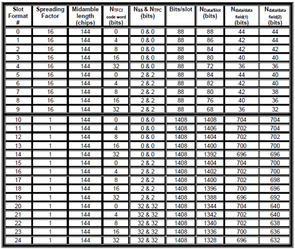
25.221 Table 8F. Time slot formats for the downlink, 1.28 Mcps TDD with QPSK. The SF sets the size of the slot, and the TFCI, SS and TPC fields take their bits out of it.
Bits/slot follows from the SF : a traffic burst has two data fields of 352 chips. At SF 16 that is 2 x 22 QPSK symbols, which is 88 bits. At SF 1 it is 2 x 352 symbols, which is 1408 bits.The TFCI column is the whole code word : one slot carries half of it, because the code word is split over the two sub-frames of a radio frame. Slot format 13 therefore has 1408 - 8 = 1400 data bits.SS and TPC come in three sizes : 0 and 0, 2 and 2, or 32 and 32 bits. The 32 and 32 rows exist only at SF 1, where the IE value sixteenOverSF means 16 symbols.The midamble is always 144 chips : it takes no data bits, and it does not help to choose a row.The image matches the current table : the values agree with Table 8F in 25.221 v19.0.0.
Where do the TFCI, SS and TPC sit in a slot ?
The table gives only bit counts. To see why the two data fields of a slot can differ in size, we need the positions of the fields. 25.221 subclauses 5A.2.2.1 to 5A.2.2.3 give them, and the two figures below draw them for one slot of each sub-frame.
Figure 1 shows a slot without SS and TPC. Each slot of 864 chips has a data field, a midamble, a second data field and a guard period. The TFCI parts, drawn in green, sit directly next to the midamble on both sides. The first sub-frame carries the 1st and 2nd parts of the TFCI code word, and the second sub-frame carries the 3rd and 4th parts.

Figure 1. Slot without SS and TPC. The TFCI code word is split into four parts, two on each side of the midamble in each sub-frame.
The code word is spread over two sub-frames : one radio frame of 10 ms has two sub-frames of 5 ms. So each slot carries only half of the TFCI code word.Both data fields lose the same number of bits : each half of the code word is split again around the midamble. That is why slot format 3 has 40 and 40 data bits.
Figure 2 adds the SS and TPC symbols. The SS symbol, in red, comes directly after the midamble, and the TPC symbol, in light blue, follows it. The second TFCI part moves behind the TPC symbol. The label under the right half says "first subframe", but the parts drawn there are the 3rd and 4th, so that half shows the second sub-frame, as in Figure 1.
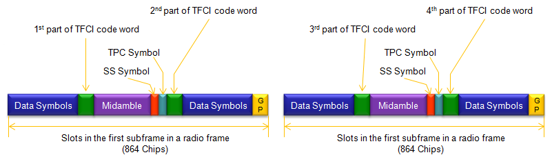
Figure 2. Slot with SS and TPC. The SS and TPC symbols follow the midamble, so they shorten only the second data field.
SS comes first, then TPC : 25.221 transmits the TPC directly after the SS, which follows the midamble.The second data field is the shorter one : slot format 8 has 40 bits in the first data field and 36 bits in the second.One channel per timeslot carries these fields : the physical channel with the lowest physical channel sequence number carries the TFCI, SS and TPC. Higher layers can add more channels for SS and TPC.
Which physical channel parameters does the example start from ?
Now let's apply the table to a real bearer. The parameters below are the downlink physical channel parameters of the reference radio bearer for Interactive or background, UL 64 and DL 384 kbps PS RAB, in 34.108 subclause 6.11.5.4.1.32.2.2. They give the resources of one radio frame, but they do not name a slot format.
How to select (figure out) slotformat ? Let's talk about following table as an example.
|
DPCH |
Modulation |
QPSK |
Line No |
||||||||||||||
|
Codes and time slots / radio frame |
SF1 x 1 code x 6 time slots |
(1) |
|||||||||||||||
|
Max. Number of data bits/radio frame |
8424 bits |
(2) |
|||||||||||||||
|
TFCI code word / radio frame |
16 bits |
(3) |
|||||||||||||||
|
TPC / radio frame |
2x2 bits |
(4) |
|||||||||||||||
|
SS / radio frame |
2x2 bits |
(5) |
|||||||||||||||
|
Puncturing Limit |
0.64 |
(6) |
|||||||||||||||
Each line of the table constrains the choice in a different way.
Line No 1 fixes the resources : one SF 1 code in six timeslots per radio frame, which is three timeslots per sub-frame.Line No 2 is the target : the six slots together must carry 8424 data bits per radio frame.Line No 3 to 5 give the layer 1 control fields : a 16-bit TFCI code word per radio frame. TPC and SS each get 2 bits in each of the two sub-frames.Line No 6 belongs to rate matching : the puncturing limit of 0.64 does not change the slot format. It limits how much rate matching may puncture.
Steps 1 to 4 - which slot format fits the bearer ?
The first four steps treat all six slots alike. Each step compares one line of the parameter table with one column of Table 8F and removes the rows that do not match.
Step 1 - which slot formats use SF 1 ?
The spreading factor splits Table 8F into two halves, so it is the first filter. Line No 1 gives SF 1, and the downlink of 1.28 Mcps TDD uses only SF 1 or SF 16.
Step 1 : Find all the possible slot formats from Table 8F based on Line No (1).
It says this is using SF1, so all the possible slot formats are 10,11,12,13,14,15,16,17,18,19,20,21,22,23,24.
Step 2 - which of them carry 16 TFCI bits ?
Line No 3 gives a TFCI code word of 16 bits per radio frame. In Table 8F, the TFCI column counts this whole code word, so we compare it with 16 directly.
Step 2 : Find all the possible slot formats from the result of Step 1 based on Line No (3).
It says the TFCI code word of the slot is 16 bits. so the possible slot formats are 13,18,23.
Step 3 - which of them carry 2 and 2 SS and TPC bits ?
Line No 4 and Line No 5 give 2 x 2 bits of TPC and of SS per radio frame. That is one QPSK symbol of each in every sub-frame, which is the 2 & 2 column of Table 8F.
Step 3 : Find all the possible slot formats from the result of Step 2 based on Line No (4).
It says the TPC of the slot is 2x2. so the possible slot formats are 18. Now we picked only one cadidate.. so no need for further checking.
Step 4 - does slot format 18 give the right bit count ?
A slot format that matches the columns can still carry the wrong number of data bits. So we multiply its data bits by the number of slots and compare the result with Line No 2.
Step 4 : Based on Step 3 and Line No (1), (2).. check if this slot is valid.
Ndata for slot : 1396 , based on Slotformat 18 in Table 8F
Number of slots per radio frame : 6, based on line number (1)
Total Number of Bits per radio frame = 1396 x 6 = 8376. This may be acceptable since it is less than 8424 (Line No (2)). But this may be a waste of small space (8424-8376 = 48 bits).
The gap of 48 bits is 4 x 12 bits. Every slot in format 18 gives up 12 bits: 8 bits for its half of the TFCI code word and 4 bits for SS and TPC. But only one slot per sub-frame needs these fields. So four of the six slots give up 12 bits each without need, and the next steps use that.
Three columns select one row : SF 1, 16 TFCI bits and 2 & 2 SS and TPC bits give slot format 18.Slot format 18 carries 1396 data bits : that is 1408 - 8 - 2 - 2.Six slots of format 18 miss the target by 48 bits : 8376 bits against the 8424 bits of Line No 2.
Steps 5 to 7 - how can the frame carry exactly 8424 bits ?
The first four steps gave every slot the same format. The last three steps drop that assumption. 25.221 lets the network decide per timeslot whether a slot carries the TFCI and the SS and TPC symbols. So only some slots need to pay for them.
Step 5 - which slots can drop the TFCI, SS and TPC ?
Let's see how often the control fields must appear. The TPC and the SS must be sent at least once per 5 ms sub-frame, and the TFCI is set per timeslot, so one slot in each sub-frame is enough.
Step 5 : Now let's think if there is any way to fully fill out bits to the max allowed bit rate.
According to Line No (1). This bearer uses 6 slots per radio frame. It means the bearer uses 3 slots per each subframe.
It may not be a good idea to send data without Ntfci and TPC at the first slot, but we are allowed to send data without Ntfci and TPC at following slots within a subframe. In stead of removing the Ntfci and TPC, we can allocate a little bit larger Ndata for that slot and increase the throughput a little bit more.
Let's find the slot format that meets the condition on Line No (1) and carries no TPC (TPC bit = 0) and Ntfci (Ntfci = 0).
What is it ? You can find only one candidate for this. It is slot format 10.
Now I am trying to allocate slot format as shown below.
Figure 3 draws the result. Two sub-frames sit side by side, and each has Slot 0 to Slot 6 with the DwPTS, the guard period and the UpPTS in grey. The dlDPCH fills Slot 4, Slot 5 and Slot 6 of each sub-frame across all 16 code rows, because one SF 1 code fills the whole slot. Slot 4 uses slot format 18, and Slot 5 and Slot 6 use slot format 10.
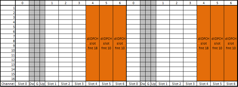
Figure 3. Slot allocation of the DL 384 kbps DPCH. The first slot of each sub-frame carries the TFCI, SS and TPC, and the other two carry only data.
Slot 4 carries the control fields : slot format 18, with 1396 data bits.Slot 5 and Slot 6 carry only data : slot format 10, with 1408 data bits each.The pattern repeats in both sub-frames : so the TFCI code word is complete in each radio frame, and SS and TPC arrive once per sub-frame.
Step 6 - does the mixed allocation give 8424 bits ?
Now we repeat the check of Step 4 with the mixed allocation. Each sub-frame contributes 1396 + 1408 + 1408 = 4212 bits, and two sub-frames give the total below.
Step 6 : Based on the result of Step 4 and 5, Line No (1), (2).. check if this slot allocation is valid.
i) Ndata for slot 4, subframe 1 (Slot format #18) = 1396
ii) Ndata for slot 5, subframe 1 (Slot format #10) = 1408
iii) Ndata for slot 6, subframe 1 (Slot format #10) = 1408
iv) Ndata for slot 4, subframe 2 (Slot format #18) = 1396
v) Ndata for slot 5, subframe 2 (Slot format #10) = 1408
vi) Ndata for slot 6, subframe 2 (Slot format #10) = 1408
-------------------------------------------------------
Total number of bits = 8424
This matches exactly with the number in Line No (2)
Step 7 - how does RRC signal the mixed allocation ?
The last step writes the allocation into the RRC message. Each timeslot needs its own tfci-Existence and ss-TPC-Symbols, so the three timeslots cannot share one set of parameters.
Step 7 : Configure RB Setup according to this configuration.
Decoded dl-CCTrCH-TimeslotsCodes from a tester log,
+-dl-CCTrCH-TimeslotsCodes ::= SEQUENCE OPTIONAL:Exist
  +-firstIndividualTimeslotInfo ::= SEQUENCE [0]
  | +-timeslotNumber ::= INTEGER (0..6) [4]
  | +-tfci-Existence ::= BOOLEAN [TRUE]
  | +-midambleShiftAndBurstType ::= SEQUENCE
  | | +-midambleAllocationMode ::= CHOICE [defaultMidamble]
  | | | +-defaultMidamble ::= NULL
  | | +-midambleConfiguration ::= INTEGER (1..8) [4]
  | +-modulation ::= ENUMERATED [mod-QPSK]
  | +-ss-TPC-Symbols ::= ENUMERATED [one]
  | +-additionalSS-TPC-Symbols ::= INTEGER OPTIONAL:Omit
  +-dl-TS-ChannelisationCodesShort ::= SEQUENCE
  | +-codesRepresentation ::= CHOICE [bitmap]
  |   +-bitmap ::= BIT STRING [0000000000000000]
  +-moreTimeslots ::= CHOICE [additionalTimeslots]
    +-additionalTimeslots ::= CHOICE [timeslotList]
      +-timeslotList ::= SEQUENCE OF SIZE(1..maxTS-LCR-1[5]) [2]
        +-DownlinkAdditionalTimeslots-LCR-r4 ::= SEQUENCE
        | +-parameters ::= CHOICE [newParameters]
        |   +-newParameters ::= SEQUENCE
        |     +-individualTimeslotInfo ::= SEQUENCE [0]
        |     | +-timeslotNumber ::= INTEGER (0..6) [5]
        |     | +-tfci-Existence ::= BOOLEAN [FALSE]
        |     | +-midambleShiftAndBurstType ::= SEQUENCE
        |     | | +-midambleAllocationMode ::= CHOICE [defaultMidamble]
        |     | | | +-defaultMidamble ::= NULL
        |     | | +-midambleConfiguration ::= INTEGER (1..8) [4]
        |     | +-modulation ::= ENUMERATED [mod-QPSK]
        |     | +-ss-TPC-Symbols ::= ENUMERATED [zero]
        |     | +-additionalSS-TPC-Symbols ::= INTEGER OPTIONAL:Omit
        |     +-dl-TS-ChannelisationCodesShort ::= SEQUENCE
        |       +-codesRepresentation ::= CHOICE [bitmap]
        |         +-bitmap ::= BIT STRING [0000000000000000]
        +-DownlinkAdditionalTimeslots-LCR-r4 ::= SEQUENCE
          +-parameters ::= CHOICE [newParameters]
            +-newParameters ::= SEQUENCE
              +-individualTimeslotInfo ::= SEQUENCE [0]
              | +-timeslotNumber ::= INTEGER (0..6) [6]
              | +-tfci-Existence ::= BOOLEAN [FALSE]
              | +-midambleShiftAndBurstType ::= SEQUENCE
              | | +-midambleAllocationMode ::= CHOICE [defaultMidamble]
              | | | +-defaultMidamble ::= NULL
              | | +-midambleConfiguration ::= INTEGER (1..8) [4]
              | +-modulation ::= ENUMERATED [mod-QPSK]
              | +-ss-TPC-Symbols ::= ENUMERATED [zero]
              | +-additionalSS-TPC-Symbols ::= INTEGER OPTIONAL:Omit
              +-dl-TS-ChannelisationCodesShort ::= SEQUENCE
                +-codesRepresentation ::= CHOICE [bitmap]
                  +-bitmap ::= BIT STRING [0000000000000000]
The tree follows DownlinkTimeslotsCodes-LCR-r4. The first timeslot, timeslot 4, carries tfci-Existence TRUE and ss-TPC-Symbols one, which gives slot format 18. The timeslotList then adds timeslot 5 and timeslot 6 with tfci-Existence FALSE and ss-TPC-Symbols zero, which gives slot format 10. Every bitmap is all zero, and 25.331 subclause 10.3.6.17 reads that as SF 1.
The consecutive option of moreTimeslots would not work here, because it gives the additional timeslots the same parameters as the first one. Timeslot 6 could use sameAsLast instead of newParameters, because its parameters equal those of timeslot 5. The capture spells them out in full, which is also valid.
Following is based on
DownlinkTimeslotsCodes-LCR-r4 ::=	SEQUENCE {
	firstIndividualTimeslotInfo			IndividualTimeslotInfo-LCR-r4,
	dl-TS-ChannelisationCodesShort		DL-TS-ChannelisationCodesShort,
	moreTimeslots						CHOICE {
		noMore								NULL,
		additionalTimeslots					CHOICE {
			consecutive							INTEGER (1..maxTS-LCR-1),
			timeslotList						SEQUENCE (SIZE (1..maxTS-LCR-1)) OF
													DownlinkAdditionalTimeslots-LCR-r4
		}
	}
}

DownlinkAdditionalTimeslots-LCR-r4 ::=	SEQUENCE {
	parameters							CHOICE {
		sameAsLast							SEQUENCE {
			timeslotNumber						TimeslotNumber-LCR-r4
		},
		newParameters						SEQUENCE {
			individualTimeslotInfo				IndividualTimeslotInfo-LCR-r4,
			dl-TS-ChannelisationCodesShort		DL-TS-ChannelisationCodesShort
		}
	}
}
Only one slot per sub-frame needs the control fields : the TFCI is set per timeslot, and SS and TPC need to appear once per sub-frame.Mixing slot formats fills the frame exactly : 2 x 1396 + 4 x 1408 = 8424 bits, the value of Line No 2.RRC signals the slot format indirectly : tfci-Existence and ss-TPC-Symbols per timeslot, with an all-zero bitmap for SF 1.newParameters is needed when a timeslot differs : sameAsLast and consecutive copy the parameters of another timeslot.
Reference
- 25.221 Physical channels and mapping of transport channels onto physical channels TDD - v19.0.0, subclauses 5A.2.2 Burst format, 5A.2.2.1 Transmission of TFCI, 5A.2.2.2 Transmission of TPC, 5A.2.2.3 Transmission of SS and Table 8F
- 25.331 Radio Resource Control RRC protocol specification - v19.0.1, subclauses 10.3.6.17 Downlink channelisation codes and 10.3.6.32 Downlink Timeslots and Codes
- 34.108 Common test environments for User Equipment conformance testing - v15.2.0, subclause 6.11.5.4.1.32.2.2 Physical channel parameters