This page is to give you a general idea of how you can figure out (determin) from RRC message (higher layer information) which slot format (PHY parameter) should be used.
Let's assume that you have a RRC message (e.g, Radio Bearer Setup) and 25.221 Table 8F as reference, what is the slot format this RRC message refering to ?
The worked example below uses the downlink DPCH of a 1.28 Mcps TDD cell, the TDD option that TD-SCDMA networks use. The RRC message never names a slot format. Instead, the UE works it out from three RRC fields, and each field removes some rows of the table. The values are checked against 25.221 v19.0.0 and 25.331 v19.0.1.
The topics on this page are listed below.
- Which RRC fields and which table do you need ?
- Step 1 : Determine Spreading Factor.
- Step 2 : Check TFCI Field.
- Step 3 : Check Nss & TPC field
- Does slot format 8 apply to every code in the timeslot ?
- Reference
Which RRC fields and which table do you need ?
Let's collect the two inputs first. One input is the physical channel part of the RRC message, which describes the DL CCTrCH timeslot by timeslot. The other input is 25.221 Table 8F, which lists every downlink slot format. The slot format is the row of the table whose columns match the RRC fields.
The capture below is the DL DPCH part of a RadioBearerSetup message. The red lines are the three fields that the steps on this page use: tfci-Coding, ss-TPC-Symbols and the channelisation code bitmap.
Decoded DL-InformationPerRL-r4 from a tester log,
            | +-dl-InformationPerRL-List ::= SEQUENCE OF SIZE(1..maxRL[8]) [1] OPTIONAL:Exist
            |   +-DL-InformationPerRL-r4 ::= SEQUENCE [100]
            |     +-modeSpecificInfo ::= CHOICE [tdd]
            |     | +-tdd ::= CHOICE [tdd]
            |     |   +-tdd ::= SEQUENCE [1]
            |     |     +-tddOption ::= CHOICE [tdd128]
            |     |     | +-tdd128 ::= SEQUENCE
            |     |     |   +-tstd-Indicator ::= BOOLEAN [FALSE]
            |     |     +-cellParametersID ::= INTEGER (0..127) [127] OPTIONAL:Exist
            |     |     +-sctd-Indicator ::= BOOLEAN [FALSE]
            |     +-dl-DPCH-InfoPerRL ::= CHOICE [tdd] OPTIONAL:Exist
            |     | +-tdd ::= SEQUENCE [10]
            |     |   +-dl-CCTrChListToEstablish ::= SEQUENCE OF SIZE(1..maxCCTrCH[8]) [1] OPTIONAL:Exist
            |     |   | +-DL-CCTrCh-r4 ::= SEQUENCE [110]
            |     |   |   +-tfcs-ID ::= INTEGER (1..8) [1] OPTIONAL:Exist
            |     |   |   +-timeInfo ::= SEQUENCE [10]
            |     |   |   | +-activationTime ::= INTEGER (0..255) [0] OPTIONAL:Exist
            |     |   |   | +-durationTimeInfo ::= INTEGER OPTIONAL:Omit
            |     |   |   +-commonTimeslotInfo ::= SEQUENCE [11] OPTIONAL:Exist
            |     |   |   | +-secondInterleavingMode ::= ENUMERATED [frameRelated]
            |     |   |   | +-tfci-Coding ::= ENUMERATED [tfci-bits-16] OPTIONAL:Exist
            |     |   |   | +-puncturingLimit ::= ENUMERATED [pl0-56]
            |     |   |   | +-repetitionPeriodAndLength ::= CHOICE [repetitionPeriod1] OPTIONAL:Exist
            |     |   |   |   +-repetitionPeriod1 ::= NULL
            |     |   |   +-tddOption ::= CHOICE [tdd128]
            |     |   |   | +-tdd128 ::= SEQUENCE [1]
            |     |   |   |   +-dl-CCTrCH-TimeslotsCodes ::= SEQUENCE OPTIONAL:Exist
            |     |   |   |     +-firstIndividualTimeslotInfo ::= SEQUENCE [0]
            |     |   |   |     | +-timeslotNumber ::= INTEGER (0..6) [6]
            |     |   |   |     | +-tfci-Existence ::= BOOLEAN [TRUE]
            |     |   |   |     | +-midambleShiftAndBurstType ::= SEQUENCE
            |     |   |   |     | | +-midambleAllocationMode ::= CHOICE [defaultMidamble]
            |     |   |   |     | | | +-defaultMidamble ::= NULL
            |     |   |   |     | | +-midambleConfiguration ::= INTEGER (1..8) [4]
            |     |   |   |     | +-modulation ::= ENUMERATED [mod-QPSK]
            |     |   |   |     | +-ss-TPC-Symbols ::= ENUMERATED [one]
            |     |   |   |     | +-additionalSS-TPC-Symbols ::= INTEGER OPTIONAL:Omit
            |     |   |   |     +-dl-TS-ChannelisationCodesShort ::= SEQUENCE
            |     |   |   |     | +-codesRepresentation ::= CHOICE [bitmap]
            |     |   |   |     |   +-bitmap ::= BIT STRING  [0000000011111111]
            |     |   |   |     +-moreTimeslots ::= CHOICE [noMore]
            |     |   |   |       +-noMore ::= NULL
The CCTrCH uses one timeslot, timeslotNumber 6, with the default midamble allocation and QPSK. The timeslot carries a TFCI, because tfci-Existence is TRUE. The IE tfci-Coding sits one level higher, in commonTimeslotInfo, so it applies to every timeslot of this CCTrCH. The last three fields describe the codes of the timeslot.
The table below is 25.221 Table 8F for QPSK. Each row is one slot format. The columns give the spreading factor, the midamble length, the TFCI code word bits, the SS and TPC bits, and the number of data bits per slot and per data field. Rows 0 to 9 use SF 16, and rows 10 to 24 use SF 1.
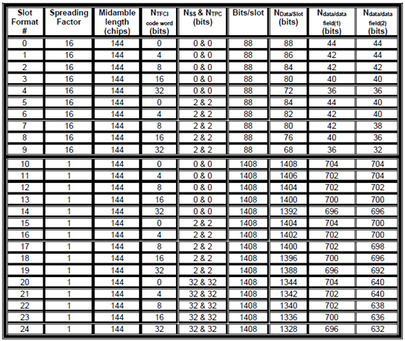
25.221 Table 8F. Time slot formats for the downlink, 1.28 Mcps TDD with QPSK. Three columns, SF, NTFCI and NSS and NTPC, are enough to pick one row.
The midamble is always 144 chips : this column does not help to choose a row.Bits/slot follows from the SF : a 1.28 Mcps traffic burst has two data fields of 352 chips. At SF 16 that is 2 x 22 QPSK symbols, which is 88 bits. At SF 1 it is 1408 bits.NData/Slot is what is left for data : the TFCI, SS and TPC bits come out of the 88 or 1408 bits. The TFCI code word is split over the two sub-frames of a radio frame, so one slot carries half of it. For slot format 8, that gives 88 - 8 - 2 - 2 = 76 bits.SS and TPC come in three sizes : 0 and 0, 2 and 2, or 32 and 32 bits. The last size exists only at SF 1, where 16/SF symbols means 16 symbols.The image matches the current table : the values agree with Table 8F in 25.221 v19.0.0, including 42 and 44 bits for the two data fields of slot format 1.
There can be many different ways.. but following is my approach.
The RRC message never names a slot format : the UE derives it from the SF, the TFCI coding and the SS and TPC symbols.tfci-Coding is common to the CCTrCH : it sits in commonTimeslotInfo. The fields tfci-Existence, ss-TPC-Symbols and the codes are set per timeslot.Each step removes rows : the SF leaves ten rows, the TFCI leaves two, and SS and TPC leave one.
Step 1 : Determine Spreading Factor.
The information (hints) on Spreading Factor in RRC message is not clear, it requires some other background knowledge around this. In case of DL DPCH, only two SF can be used. SF = 16 or SF = 1.
Which one of these two we have to pick ?
You can find some hints on this from following IE. According to 3GPP spec, if SF = 1, you MUST set all 0 at the bitmap field. If it is 'Not All 0', it means SF is 16.
Decoded DL-TS-ChannelisationCodesShort from the tester log above,
            |     |   |   |     +-dl-TS-ChannelisationCodesShort ::= SEQUENCE
            |     |   |   |     | +-codesRepresentation ::= CHOICE [bitmap]
            |     |   |   |     |   +-bitmap ::= BIT STRING  [0000000011111111]
In this example, SF turned out to be 16. So the slot format candiates are 0,1,2,3,4,5,6,7,8,9.
The rule comes from 25.331 subclause 10.3.6.17. Each bit of the bitmap marks one SF 16 channelisation code as used or not used. If all bits are set to zero, SF 1 shall be used. So an SF 1 timeslot needs no code number, because one SF 1 code fills the whole timeslot.
The bitmap also tells how many codes the UE receives. In the ASN.1, the named bits run from chCode16-SF16 for bit 0 to chCode1-SF16 for bit 15. The string 0000000011111111 therefore sets bits 8 to 15, which are codes 8 down to 1. So the UE receives eight SF 16 codes, codes 1 to 8, in timeslot 6. The SF of 16 applies to all eight codes, so the first step does not depend on the code count.
The downlink uses only SF 1 or SF 16 : this is why one bitmap is enough to decide the SF.An all-zero bitmap means SF 1 : any other bitmap means SF 16, with one code per bit that is set.This example uses eight SF 16 codes : the bitmap 0000000011111111 selects codes 1 to 8 of timeslot 6.
Step 2 : Check TFCI Field.
With the SF known, ten rows are left, and they differ in the TFCI and in the SS and TPC columns. Let's take the TFCI column next, because the RRC message gives its size directly.
As shown below, TFCI 'Exists' and the size of the field is 16 bits.
Decoded commonTimeslotInfo field from the tester log above,
| | | | +-tfci-Coding ::= ENUMERATED [tfci-bits-16] OPTIONAL:Exist
Now the number of candiates get down to only two, slot format 3 and 8.
The IE tfci-Coding gives the number of bits in the TFCI code word, and its values are 4, 8, 16 and 32. The field alone is not enough, however. The timeslot must also carry the TFCI, and here tfci-Existence is TRUE. If tfci-Existence were FALSE, the TFCI column of this timeslot would be 0, and the candidates would be slot formats 0 and 5.
The TFCI column of Table 8F counts the whole code word. One slot carries only half of it, because 25.221 subclause 5A.2.2.1 distributes the code word equally over the two sub-frames. You can check this in the table: slot format 3 has 88 - 8 = 80 data bits, not 88 - 16 = 72.
Two fields decide the TFCI column : tfci-Existence of the timeslot and tfci-Coding of the CCTrCH.tfci-bits-16 selects the rows with 16 TFCI bits : at SF 16 these are slot formats 3 and 8.Half of the code word goes in each sub-frame : so a 16-bit code word costs 8 bits of each slot.
Step 3 : Check Nss & TPC field
As shown below, SS & TPC field Exists and the size of field 2 & 2. ('one' means one SS field and one TPC field, each of which needs 2 bits to represent its value).
Decoded individual timeslot field from the tester log above,
| | | | | +-ss-TPC-Symbols ::= ENUMERATED [one]
Now you get only one candidate which is Slot Format 8. This is the final answer of this tutorial.
The IE ss-TPC-Symbols has three values: zero, one and sixteenOverSF. With QPSK, one symbol is 2 bits. So "one" gives 2 SS bits and 2 TPC bits, which is the "2 & 2" of slot formats 5 to 9. At SF 16, sixteenOverSF also means one symbol, so it leads to the same rows. At SF 1 it means 16 symbols, which is the "32 & 32" of slot formats 20 to 24.
Slot formats 3 and 8 differ only in this column. Slot format 3 has 0 SS and 0 TPC bits, and slot format 8 has 2 and 2. So the answer is slot format 8, with 76 data bits: 40 in the first data field and 36 in the second.
"one" means 2 SS bits and 2 TPC bits with QPSK : this selects the 2 & 2 rows.Slot format 8 is SF 16, 16 TFCI bits, 2 and 2 SS and TPC bits : it leaves 76 data bits per slot.The SS and TPC bits sit after the midamble : that is why the second data field is 4 bits shorter than the first one.
Does slot format 8 apply to every code in the timeslot ?
The three steps treat the timeslot as one channel. But the bitmap in Step 1 gives the UE eight SF 16 codes in timeslot 6. So we should ask whether all eight codes carry a TFCI, SS and TPC.
25.221 answers this in subclauses 5A.2.2.1 to 5A.2.2.3. If a timeslot contains the TFCI, the TFCI is transmitted on the physical channel with the lowest physical channel sequence number p in that timeslot. The TPC symbols and the SS symbols follow the same rule. Higher layers can add more channels for TPC and SS with additionalSS-TPC-Symbols, but this IE is omitted in the capture above. The rate matching function of 25.222 decides the sequence number p.
So slot format 8 applies to one physical channel of timeslot 6, the one with the lowest p. The other seven codes carry neither TFCI nor SS nor TPC. At SF 16, that matches the row of slot format 0, with 88 data bits. The tutorial answer is right for the channel that carries the layer 1 control fields, and the other codes of the same timeslot use a different row.
The listing below holds the 25.331 definitions of the fields that the three steps use. The IE tfci-Coding comes from CommonTimeslotInfo, and ss-TPC-Symbols comes from IndividualTimeslotInfo-LCR-r4.
Following is based on
IndividualTimeslotInfo-LCR-r4 ::=	SEQUENCE {
	timeslotNumber						TimeslotNumber-LCR-r4,
	tfci-Existence						BOOLEAN,
	midambleShiftAndBurstType			MidambleShiftAndBurstType-LCR-r4,
	modulation							ENUMERATED { mod-QPSK, mod-8PSK },
	ss-TPC-Symbols						ENUMERATED { zero, one, sixteenOverSF },
	additionalSS-TPC-Symbols			INTEGER(1..15)		OPTIONAL
}

CommonTimeslotInfo ::=				SEQUENCE {
	-- TABULAR: secondInterleavingMode is MD, but since it can be encoded in a single
	-- bit it is not defined as OPTIONAL.
	secondInterleavingMode				SecondInterleavingMode,
	tfci-Coding							TFCI-Coding							OPTIONAL,
	puncturingLimit						PuncturingLimit,
	repetitionPeriodAndLength			RepetitionPeriodAndLength			OPTIONAL
}

TFCI-Coding ::=						ENUMERATED {
										tfci-bits-4, tfci-bits-8,
										tfci-bits-16, tfci-bits-32 }

DL-TS-ChannelisationCodesShort ::=	SEQUENCE {
	codesRepresentation					CHOICE {
		consecutive							SEQUENCE {
			firstChannelisationCode				DL-TS-ChannelisationCode,
			lastChannelisationCode				DL-TS-ChannelisationCode
		},
		bitmap								BIT STRING {
												chCode16-SF16(0),
												chCode15-SF16(1),
												chCode14-SF16(2),
												chCode13-SF16(3),
												chCode12-SF16(4),
												chCode11-SF16(5),
												chCode10-SF16(6),
												chCode9-SF16(7),
												chCode8-SF16(8),
												chCode7-SF16(9),
												chCode6-SF16(10),
												chCode5-SF16(11),
												chCode4-SF16(12),
												chCode3-SF16(13),
												chCode2-SF16(14),
												chCode1-SF16(15)
												} 	(SIZE (16))
	}
}
TFCI, SS and TPC go on one channel per timeslot : the physical channel with the lowest sequence number p carries them, unless additional channels are configured.One timeslot can hold two slot formats : in this example, one code uses slot format 8 and the other seven use slot format 0.additionalSS-TPC-Symbols changes the answer : when it is present, more codes carry SS and TPC bits and move to the 2 & 2 rows.
Reference
- 25.221 Physical channels and mapping of transport channels onto physical channels TDD - v19.0.0, subclauses 5A.2.2 Burst format, 5A.2.2.1 Transmission of TFCI, 5A.2.2.2 Transmission of TPC, 5A.2.2.3 Transmission of SS and Table 8F
- 25.331 Radio Resource Control RRC protocol specification - v19.0.1, subclauses 10.3.6.10 Common timeslot info, 10.3.6.17 Downlink channelisation codes and 10.3.6.37 Individual timeslot info